Moran M.J., Shapiro H.N. Fundamentals of Engineering Thermodynamics
Подождите немного. Документ загружается.

266 Chapter 6 Using Entropy
incompressible. Plot the minimum theoretical heat addition re-
quired, in Btu per lb of cool water exiting the device, versus
T ranging from 60 to 100F.
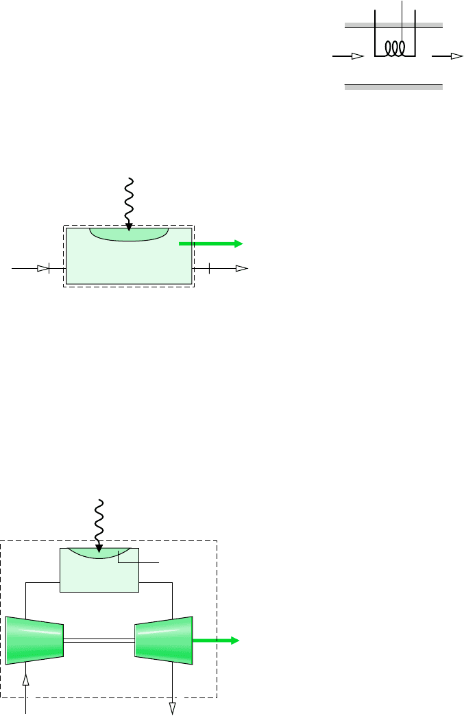
6.75 Figure P6.75 shows a proposed device to develop power
using energy supplied to the device by heat transfer from a
high-temperature industrial process together with a steam in-
put. The figure provides data for steady-state operation. All
surfaces are well insulated except for the one at 527C, through
which heat transfer occurs at a rate of 4.21 kW. Ignoring
changes in kinetic and potential energy, evaluate the maximum
theoretical power that can be developed, in kW.
The air enters the duct at 15C, 1 atm and exits at 25C with
a negligible change in pressure. Kinetic and potential energy
changes can be ignored.
(a) For the resistor as the system, determine the rate of en-
tropy production, in kW/K.
(b) For a control volume enclosing the air in the duct and the
resistor, determine the volumetric flow rate of the air en-
tering the duct, in m
3
/s, and rate of entropy production, in
kW/K.
Why do the entropy production values of (a) and (b) differ?
6.78 For the computer of Example 4.8, determine the rate of
entropy production, in W/K, when air exits at 32C. Ignore the
change in pressure between the inlet and exit.
6.79 For the computer of Problem 4.70, determine the rate of
entropy production, in kW/K, ignoring the change in pressure
between the inlet and exit.
6.80 For the water-jacketed electronics housing of Problem
4.71, determine the rate of entropy production, in kW/K, when
water exits at 26C.
6.81 For the electronics-laden cylinder of Problem 4.73,
determine the rate of entropy production, in W/K, when air
exits at 40C with a negligible change in pressure. Assume con-
vective cooling occurs on the outer surface of the cylinder in
accord with hA 3.4 W/K, where h is the heat transfer coef-
ficient and A is the surface area. The temperature of the
surroundings away from the vicinity of the cylinder is 25C.
6.82 Steam enters a horizontal 15-cm-diameter pipe as a satu-
rated vapor at 5 bar with a velocity of 10 m/s and exits at 4.5 bar
with a quality of 95%. Heat transfer from the pipe to the
surroundings at 300 K takes place at an average outer surface
temperature of 400 K. For operation at steady state, determine
(a) the velocity at the exit, in m /s.
(b) the rate of heat transfer from the pipe, in kW.
(c) the rate of entropy production, in kW/K, for a control
volume comprising only the pipe and its contents.
(d) the rate of entropy production, in kW/K, for an enlarged
control volume that includes the pipe and enough of its
immediate surroundings so that heat transfer from the con-
trol volume occurs at 300 K.
Why do the answers of parts (c) and (d) differ?
6.83 Steam enters a turbine operating at steady state at a
pressure of 3 MPa, a temperature of 400C, and a velocity of
160 m/s. Saturated vapor exits at 100C, with a velocity of
100 m/s. Heat transfer from the turbine to its surroundings
1 bar2
Steam at 3 bar
500°C, 1.58 kg/min
527°C
Q
·
cv
= 4.21 kW
W
·
cv
1
Figure P6.75
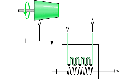
6.76 Figure P6.76 shows a gas turbine power plant operat-
ing at steady state consisting of a compressor, a heat exchanger,
and a turbine. Air enters the compressor with a mass flow rate
of 3.9 kg/s at 0.95 bar, 22C and exits the turbine at 0.95 bar,
421C. Heat transfer to the air as it flows through the heat ex-
changer occurs at an average temperature of 488C. The com-
pressor and turbine operate adiabatically. Using the ideal gas
model for the air, and neglecting kinetic and potential energy
effects, determine the maximum theoretical value for the net
power that can be developed by the power plant, in MW.
Air at
0.95 bar, 22°C
Air at
0.95 bar, 421°C
Heat exchanger
T = 488°C
W
·
net
1 2
Compressor Turbine
Figure P6.76
6.77 Figure P6.77 shows a 30-ohm electrical resistor located
in an insulated duct carrying a stream of air. At steady state,
an electric current of 15 amp passes through the resistor, whose
temperature remains constant at 127C.
Air out at 25°C
30-ohm resistor, T = 127°C
+–
Air in at
15°C, 1 atm
Figure P6.77
Problems: Developing Engineering Skills 267
takes place at the rate of 30 kJ per kg of steam at a location
where the average surface temperature is 350 K.
(a) For a control volume including only the turbine and its
contents, determine the work developed, in kJ, and the rate
at which entropy is produced, in kJ/K, each per kg of steam
flowing.
(b) The steam turbine of part (a) is located in a factory where
the ambient temperature is 27C. Determine the rate of en-
tropy production, in kJ/K per kg of steam flowing, for an
enlarged control volume that includes the turbine and enough
of its immediate surroundings so that heat transfer takes place
from the control volume at the ambient temperature.
Explain why the entropy production value of part (b) differs
from that calculated in part (a).
6.84 Carbon dioxide (CO
2
) enters a nozzle operating at steady
state at 28 bar, 267C, and 50 m/s. At the nozzle exit, the con-
ditions are 1.2 bar, 67C, 580 m/s, respectively.
(a) For a control volume enclosing the nozzle only, determine
the heat transfer, in kJ, and the change in specific entropy,
in kJ/K, each per kg of carbon dioxide flowing through the
nozzle. What additional information would be required to
evaluate the rate of entropy production?
(b) Evaluate the rate of entropy production, in kJ/K per kg of
carbon dioxide flowing, for an enlarged control volume
enclosing the nozzle and a portion of its immediate
surroundings so that the heat transfer occurs at the ambi-
ent temperature, 25C.
6.85 Air enters a compressor operating at steady state at 1 bar,
22C with a volumetric flow rate of 1 m
3
/min and is com-
pressed to 4 bar, 177C. The power input is 3.5 kW. Employing
the ideal gas model and ignoring kinetic and potential energy
effects, obtain the following results:
(a) For a control volume enclosing the compressor only, de-
termine the heat transfer rate, in kW, and the change in
specific entropy from inlet to exit, in What ad-
ditional information would be required to evaluate the rate
of entropy production?
(b) Calculate the rate of entropy production, in kW/K, for an
enlarged control volume enclosing the compressor and a
portion of its immediate surroundings so that heat trans-
fer occurs at the ambient temperature, 22C.
6.86 Air is compressed in an axial-flow compressor operating
at steady state from 27C, 1 bar to a pressure of 2.1 bar. The
work input required is 94.6 kJ per kg of air flowing through
the compressor. Heat transfer from the compressor occurs at
the rate of 14 kJ per kg at a location on the compressor’s surface
where the temperature is 40C. Kinetic and potential energy
changes can be ignored. Determine
(a) the temperature of the air at the exit, in C.
(b) the rate at which entropy is produced within the com-
pressor, in kJ/K per kg of air flowing.
6.87 Ammonia enters a counterflow heat exchanger at 20C,
with a quality of 35%, and leaves as saturated vapor at 20C.
Air at 300 K, 1 atm enters the heat exchanger in a separate
kJ/kg
#
K.
stream with a flow rate of 4 kg/s and exits at 285 K, 0.98 atm.
The heat exchanger is at steady state, and there is no appre-
ciable heat transfer from its outer surface. Neglecting kinetic
and potential energy effects, determine the mass flow rate of
the ammonia, in kg/s, and the rate of entropy production within
the heat exchanger, in kW/K.
6.88 A counterflow heat exchanger operates at steady state
with negligible kinetic and potential energy effects. In one
stream, liquid water enters at 15C and exits at 23C with a
negligible change in pressure. In the other stream, Refrigerant
22 enters at 12 bar, 90C with a mass flow rate of 150 kg/h
and exits at 12 bar, 28C. Heat transfer from the outer surface
of the heat exchanger can be ignored. Determine
(a) the mass flow rate of the liquid water stream, in kg/h.
(b) the rate of entropy production within the heat exchanger,
in kW/K.
6.89 Steam at 0.7 MPa, 355C enters an open feedwater heater
operating at steady state. A separate stream of liquid water en-
ters at 0.7 MPa, 35C. A single mixed stream exits as saturated
liquid at pressure p. Heat transfer with the surroundings and
kinetic and potential energy effects can be ignored.
(a) If p 0.7 MPa, determine the ratio of the mass flow rates
of the incoming streams and the rate at which entropy is
produced within the feedwater heater, in kJ/K per kg of
liquid exiting.
(b) Plot the quantities of part (a), each versus pressure p rang-
ing from 0.6 to 0.7 MPa.
6.90 Air as an ideal gas flows through the compressor and heat
exchanger shown in Fig. P6.90. A separate liquid water stream
also flows through the heat exchanger. The data given are for
operation at steady state. Stray heat transfer to the surround-
ings can be neglected, as can all kinetic and potential energy
changes. Determine
(a) the compressor power, in kW, and the mass flow rate of
the cooling water, in kg/s.
(b) the rates of entropy production, each in kW/K, for the com-
pressor and heat exchanger.
Compressor
p
1
= 96 kPa
T
1
= 27°C
(AV)
1
= 26.91 m
3
/min
p
2
= 230 kPa
T
1
= 127°C
T
A
= 25°C T
B
= 40°C
T
3
= 77°C
p
3
= p
2
1
Air in
32
Heat
exchanger
Water
in
(A)
Water
out
(B)
Figure P6.90

268 Chapter 6 Using Entropy
6.91 Determine the rates of entropy production, each in kW/K,
for the turbines and the heat exchanger of Problem 4.82. Place
these in rank order beginning with the component contribut-
ing most to inefficient operation of the overall system.
6.92 Determine the rates of entropy production, each in kW/K,
for the turbine, condenser, and pump of Problem 4.85. Place
these in rank order beginning with the component contribut-
ing most to inefficient operation of the overall system.
6.93 For the control volume of Example 4.12, determine the
amount of entropy produced during filling, in kJ/K. Repeat for
the case where no work is developed by the turbine.
6.94 Steam is contained in a large vessel at 100 lbf/in.
2
, 450F.
Connected to the vessel by a valve is an initially evacuated
tank having a volume of 1 ft
3
. The valve is opened until the
tank is filled with steam at pressure p. The filling is adiabatic,
kinetic and potential energy effects are negligible, and the state
of the large vessel remains constant.
(a) If p 100 lbf/in.
2
, determine the final temperature of the
steam within the tank, in F, and the amount of entropy
produced within the tank, in Btu/R.
(b) Plot the quantities of part (a) versus presssure p ranging
from 10 to 100 lbf/in.
2
6.95 A well-insulated rigid tank of volume 10 m
3
is connected
by a valve to a large-diameter supply line carrying air at 227C
and 10 bar. The tank is initially evacuated. Air is allowed to
flow into the tank until the tank pressure is p. Using the ideal
gas model with constant specific heat ratio k, plot tank tem-
perature, in K, the mass of air in the tank, in kg, and the amount
of entropy produced, in kJ/K, versus p in bar.
Using Isentropic Processes/Efficiencies
6.96 A piston–cylinder assembly initially contains 0.1 m
3
of
carbon dioxide gas at 0.3 bar and 400 K. The gas is compressed
isentropically to a state where the temperature is 560 K. Em-
ploying the ideal gas model and neglecting kinetic and poten-
tial energy effects, determine the final pressure, in bar, and the
work in kJ, using
(a) data from Table A-23.
(b) IT
(c) a constant specific heat ratio from Table A-20 at the mean
temperature, 480 K.
(d) a constant specific heat ratio from Table A-20 at 300 K.
6.97 Air enters a turbine operating at steady state at 6 bar and
1100 K and expands isentropically to a state where the tem-
perature is 700 K. Employing the ideal gas model and ignoring
kinetic and potential energy changes, determine the pressure
at the exit, in bar, and the work, in kJ per kg of air flowing,
using
(a) data from Table A-22.
(b) IT.
(c) a constant specific heat ratio from Table A-20 at the mean
temperature, 900 K.
(d) a constant specific heat ratio from Table A-20 at 300 K.
6.98 Methane (CH
4
) undergoes an isentropic expansion from
an initial state where the temperature is 1000 K and the pres-
sure is 5 bar to a final state where the temperature is T and the
pressure is p. Using the ideal gas model together with
from Table A-21, determine
(a) p when T 500 K
(b) T when p 1 bar.
(c) Check the results of parts (a) and (b) using IT.
6.99 An ideal gas with constant specific heat ratio k enters a
nozzle operating at steady state at pressure p
1
, temperature T
1
,
and velocity V
1
. The air expands isentropically to a pressure
of p
2
.
(a) Develop an expression for the velocity at the exit, V
2
,in
terms of k, R,V
1
, T
1
, p
1
, and p
2
, only.
(b) For V
1
0, T
1
1000 K, plot V
2
versus p
2
p
1
for selected
values of k ranging from 1.2 to 1.4.
6.100 An ideal gas undergoes a polytropic process from T
1
, p
1
to a state where the temperature is T
2
.
(a) Derive an expression for the change in specific entropy in
terms of n, R, T
1
, T
2
, s(T
1
), and s(T
2
).
(b) Using the result of part (a), develop an expression for n if
s
1
s
2
.
6.101 A rigid well-insulated tank having a volume of 0.2 m
3
is
filled initially with Refrigerant 134a vapor at a pressure of
10 bar and a temperature of 40C. A leak develops and refrig-
erant slowly escapes until the pressure within the tank becomes
1 bar. Determine
(a) the final temperature of the refrigerant within the tank, in C.
(b) the amount of mass that exits the tank, in kg.
6.102 A rigid tank is filled initially with 5.0 kg of air at a pres-
sure of 0.5 MPa and a temperature of 500 K. The air is allowed
to discharge through a turbine into the atmosphere, developing
work until the pressure in the tank has fallen to the atmospheric
level of 0.1 MPa. Employing the ideal gas model for the air,
determine the maximum theoretical amount of work that could
be developed, in kJ. Ignore heat transfer with the atmosphere
and changes in kinetic and potential energy.
6.103 Air enters a 3600-kW turbine operating at steady state
with a mass flow rate of 18 kg/s at 800C, 3 bar and a velocity
of 100 m/s. The air expands adiabatically through the turbine
and exits at a velocity of 150 m/s. The air then enters a dif-
fuser where it is decelerated isentropically to a velocity of
10 m/s and a pressure of 1 bar. Employing the ideal gas model,
determine
(a) the pressure and temperature of the air at the turbine exit,
in bar and C, respectively.
(b) the rate of entropy production in the turbine, in kW/K.
(c) Show the processes on a T–s diagram.
6.104 Steam at 5 MPa and 600C enters an insulated turbine
operating at steady state and exits as saturated vapor at
50 kPa. Kinetic and potential energy effects are negligible.
c
p
(T )
Problems: Developing Engineering Skills 269
14 bar. The isentropic compressor efficiency is 75%. Heat
transfer between the compressor and its surroundings can be
ignored. Kinetic and potential energy effects are also negligi-
ble. Determine
(a) the exit temperature, in C.
(b) the work input, in kJ per kg of refrigerant flowing.
6.111 Air enters an insulated compressor operating at steady
state at 1 bar, 350 K with a mass flow rate of 1 kg/s and exits
at 4 bar. The isentropic compressor efficiency is 82%. Deter-
mine the power input, in kW, and the rate of entropy produc-
tion, in kW/K, using the ideal gas model with
(a) data from Table A-22.
(b) IT.
(c) a constant specific heat ratio, k 1.39.
6.112 A compressor operating at steady state takes in atmos-
pheric air at 20C, 1 bar at a rate of 1 kg/s and discharges air
at 5 bar. Plot the power required, in kW, and the exit temper-
ature, in C, versus the isentropic compressor efficiency rang-
ing from 70 to 100%. Assume the ideal gas model for the air
and neglect heat transfer with the surroundings and changes in
kinetic and potential energy.
6.113 In a gas turbine operating at steady state, air enters the
compressor with a mass flow rate of 5 kg/s at 0.95 bar and 22C
and exits at 5.7 bar. The air then passes through a heat exchanger
before entering the turbine at 1100 K, 5.7 bar. Air exits the tur-
bine at 0.95 bar. The compressor and turbine operate adiabati-
cally and kinetic and potential energy effects can be ignored.
Determine the net power developed by the plant, in kW, if
(a) the compressor and turbine operate without internal irre-
versibilities.
(b) the compressor and turbine isentropic efficiencies are 82
and 85%, respectively.
Analyzing Internally Reversible Flow Processes
6.114 Air enters a compressor operating at steady state at 17C,
1 bar and exits at a pressure of 5 bar. Kinetic and potential en-
ergy changes can be ignored. If there are no internal irre-
versibilities, evaluate the work and heat transfer, each in kJ per
kg of air flowing, for the following cases:
(a) isothermal compression.
(b) polytropic compression with n 1.3.
(c) adiabatic compression.
Sketch the processes on p–v and T–s coordinates and associ-
ate areas on the diagrams with the work and heat transfer in
each case. Referring to your sketches, compare for these cases
the magnitudes of the work, heat transfer, and final tempera-
tures, respectively.
6.115 Air enters a compressor operating at steady state with a
volumetric flow rate of 8 m
3
/min at 23C, 0.12 MPa. The air
is compressed isothermally without internal irreversibilities,
exiting at 1.5 MPa. Kinetic and potential energy effects can be
ignored. Evaluate the work required and the heat transfer, each
in kW.
p
1
= 4 MPa
T
1
= 360°C
m
·
1
= 11 kg/s
p
4
= 1 MPa
T
4
= 240°C
p
2
= 1 MPa
p
3
= 1 MPa
η
t
= 90%
4
Mixing
chamber
Valve
Turbine
1
2
3
Figure P6.106
6.107 Water vapor enters an insulated nozzle operating at steady
state at 0.7 MPa, 320C, 35 m/s and expands to 0.15 MPa. If
the isentropic nozzle efficiency is 94%, determine the velocity
at the exit, in m/s.
6.108 Argon enters an insulated nozzle at 2.77 bar, 1300 K,
10 m/s and exits at 1 bar, 645 m/s. For steady-state operation,
determine
(a) the exit temperature, in K.
(b) the isentropic nozzle efficiency.
(c) the rate of entropy production, in kJ/K per kg of argon
flowing.
6.109 Air enters an insulated compressor operating at steady state
at 0.95 bar, 27C with a mass flow rate of 4000 kg/h and exits
at 8.7 bar. Kinetic and potential energy effects are negligible.
(a) Determine the minimum theoretical power input required,
in kW, and the corresponding exit temperature, in C.
(b) If the exit temperature is 347C, determine the power in-
put, in kW, and the isentropic compressor efficiency.
6.110 Refrigerant 134a enters a compressor operating at steady
state as saturated vapor at 4C and exits at a pressure of
Determine
(a) the work developed by the turbine, in kJ per kg of steam
flowing through the turbine.
(b) the isentropic turbine efficiency.
6.105 Nitrogen (N
2
) at 3.8 atm and 170C enters an insulated
turbine operating at steady state and expands to 1 atm. If the
isentropic turbine efficiency is 83.2%, determine the tempera-
ture at the turbine exit, in C, using the ideal gas model for the
nitrogen and ignoring kinetic and potential energy changes.
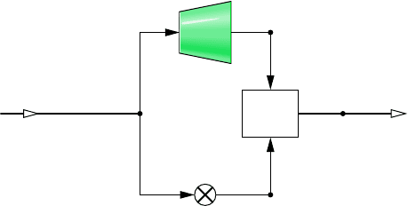
6.106 Figure P6.106 provides steady-state operating data for a
throttling valve in parallel with a steam turbine having an isen-
tropic turbine efficiency of 90%. The streams exiting the valve
and the turbine mix in a mixing chamber. Heat transfer with
the surroundings and changes in kinetic and potential energy
can be neglected. Determine
(a) the power developed by the turbine, in horsepower.
(b) the mass flow rate through the valve, in lb/s.
(c) Locate the four numbered states on an h–s diagram.
270 Chapter 6 Using Entropy
6.116 Refrigerant 134a enters a compressor operating at steady
state at 1.8 bar, 10C with a volumetric flow rate of 2.4
10
2
m
3
/s. The refrigerant is compressed to a pressure of 9 bar
in an internally reversible process according to pv
1.04
constant.
Neglecting kinetic and potential energy effects, determine
(a) the power required, in kW.
(b) the rate of heat transfer, in kW.
6.117 Compare the work required at steady state to compress
water vapor isentropically to 3 MPa from the saturated vapor
state at 0.1 MPa to the work required to pump liquid water
isentropically to 3 MPa from the saturated liquid state at
0.1 MPa, each in kJ per kg of water flowing through the device.
Kinetic and potential energy effects can be ignored.
6.118 An electrically-driven pump operating at steady state
draws water from a pond at a pressure of 1 bar and a rate of
40 kg/s and delivers the water at a pressure of 4 bar. There is
no significant heat transfer with the surroundings, and changes
in kinetic and potential energy can be neglected. The isentropic
pump efficiency is 80%. Evaluating electricity at 8 cents per
estimate the hourly cost of running the pump.
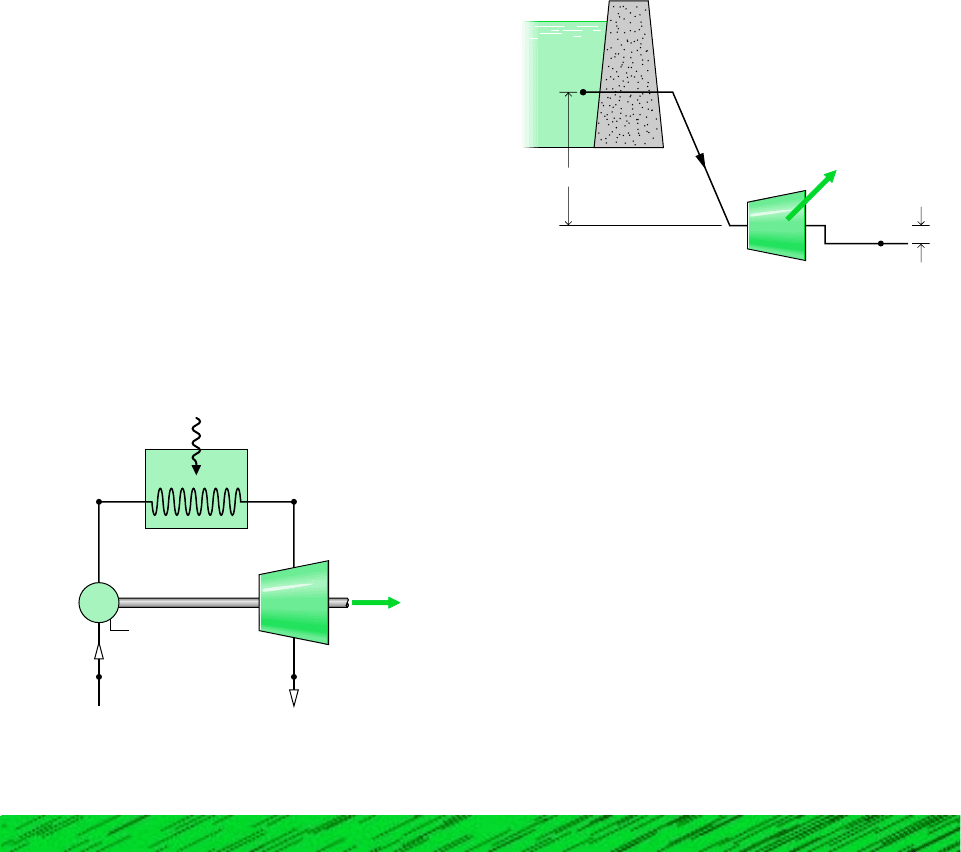
6.119 Figure P6.119 shows three devices operating at steady
state: a pump, a boiler, and a turbine. The turbine provides the
power required to drive the pump and also supplies power to
other devices. For adiabatic operation of the pump and turbine,
and ignoring kinetic and potential energy effects, determine,
in kJ per kg of steam flowing
kW
#
h,
(a) the work required by the pump.
(b) the net work developed by the turbine.
(c) the heat transfer to the boiler.
6.120 As shown in Fig. P6.120, water flows from an elevated
reservoir through a hydraulic turbine. The pipe diameter is con-
stant, and operation is at steady state. Estimate the minimum
mass flow rate, in kg/s, that would be required for a turbine power
output of 1 MW. The local acceleration of gravity is 9.8 m/s
2
.
W
·
net
Q
·
in
Pump
η
p
= 70%
2
14
3
Boiler
8 bar 8 bar,
saturated vapor
Feedwater
1 bar, 30°C
Steam
1 bar
Turbine
η
t
= 90%
Figure P6.119
p
1
= 1.3 bar
p
2
= 1.0 bar
100 m
5 m
2
1
W
·
t
= 1 MW
Figure P6.120
6.121 A 5-kilowatt pump operating at steady state draws in
liquid water at 1 bar, 15C and delivers it at 5 bar at an elevation
6 m above the inlet. There is no significant change in velocity
between the inlet and exit, and the local acceleration of grav-
ity is 9.8 m/s
2
. Would it be possible to pump 7.5 m
3
in 10 min
or less? Explain.
6.122 A 4-kW pump operating at steady state draws in liquid
water at 1 bar, 16C with a mass flow rate of 4.5 kg/s. There
are no significant kinetic and potential energy changes from
inlet to exit and the local acceleration of gravity is 9.81 m/s
2
.
Would it be possible for the pump to deliver water at a pres-
sure of 10 bar? Explain.
6.123 Carbon monoxide enters a nozzle operating at steady
state at 5 bar, 200C, 1 m/s and undergoes a polytropic ex-
pansion to 1 bar with n 1.2. Using the ideal gas model and
ignoring potential energy effects, determine
(a) the exit velocity, in m/s.
(b) the rate of heat transfer between the gas and its surround-
ings, in kJ per kg of gas flowing.
Design & Open Ended Problems: Exploring Engineering Practice
6.1D
Of increasing interest today are turbines, pumps, and heat
exchangers that weigh less than 1 gram and have volumes of
1 cubic centimeter or less. Although many of the same design
considerations apply to such micromachines as to correspon-
ding full-scale devices, others do not. Of particular interest to
designers is the impact of irreversibilities on the performance
of such tiny devices. Write a report discussing the influence of
irreversibilities related to heat transfer and friction on the de-
sign and operation of micromachines.
6.2D The growth of living organisms has been studied and in-
terpreted thermodynamically by I. Prigogine and others, using
the entropy and entropy production concepts. Write a paper
summarizing the main findings of these investigations.
Design & Open Ended Problems: Exploring Engineering Practice 271
6.7D Water is to be pumped from a lake to a reservoir located
on a bluff 290 ft above. According to the specifications, the
piping is Schedule 40 steel pipe having a nominal diameter of
1 inch and the volumetric flow rate is 10 gal/min. The total
length of pipe is 580 ft. A centrifugal pump is specified. Esti-
mate the electrical power required by the pump, in kW. Is a
centrifugal pump a good choice for this application? What pre-
cautions should be taken to avoid cavitation?
6.8D Elementary thermodynamic modeling, including the use
of the temperature–entropy diagram for water and a form of the
Bernoulli equation has been employed to study certain types of
volcanic eruptions. (See L. G. Mastin, “Thermodynamics of
Gas and Steam-Blast Eruptions,” Bull. Volcanol., 57, 85–98,
1995.) Write a report critically evaluating the underlying
assumptions and application of thermodynamic principles, as
reported in the article.
6.9D An inventor claims to have conceived of a second law-
challenging heat engine. (See H. Apsden, “The Electronic Heat
Engine,” Proceedings 27th International Energy Conversion
Engineering Conference, 4.357–4.363, 1992. Also see U.S.
Patent No. 5,101,632.) By artfully using mirrors the heat en-
gine would “efficiently convert abundant environmental heat
energy at the ambient temperature to electricity.” Write a pa-
per explaining the principles of operation of the device. Does
this invention actually challenge the second law of thermody-
namics? Does it have commercial promise? Discuss.
6.10D Noting that contemporary economic theorists often draw
on principles from mechanics such as conservation of energy
to explain the workings of economies, N. Georgescu-Roegen
and like-minded economists have called for the use of princi-
ples from thermodynamics in economics. According to this
view, entropy and the second law of thermodynamics are
relevant for assessing not only the exploitation of natural re-
sources for industrial and agricultural production but also the
impact on the natural environment of wastes from such pro-
duction. Write a paper in which you argue for, or against, the
proposition that thermodynamics is relevant to the field of
economics.
6.11D Roll Over Boltzman (see box Sec. 6.5). The new sta-
tistical definition of entropy is said to give insights about
physical systems verging on chaos. Investigate what is meant
by chaos in this context. Write a report including at least three
references.
6.12D Star Guides Consumer Choices (see box Sec. 6.8).
Using the ENERGY STAR
®
Home Improvement Toolbox, ob-
tain a rank-ordered list of the top three cost-effective im-
provements that would enhance the overall energy efficiency
of your home. Develop a plan to implement the improvements.
Write a report including at least three references.
6.3D The theoretical steam rate is the quantity of steam re-
quired to produce a unit amount of work in an ideal turbine.
The Theoretical Steam Rate Tables published by The American
Society of Mechanical Engineers give the theoretical steam rate
in lb per To determine the actual steam rate, the theo-
retical steam rate is divided by the isentropic turbine efficiency.
Why is the steam rate a significant quantity? Discuss how the
steam rate is used in practice.
6.4D Figure P6.4D illustrates an ocean thermal energy conver-
sion (OTEC ) power plant that generates power by exploiting
the naturally occurring decrease of the temperature of ocean
water with depth. Warm surface water enters the evaporator
with a mass flow rate of at temperature T
w
28C and
exits at T
1
T
w
. Cool water brought from a depth of 600 m
enters the condenser with a mass flow rate of at tempera-
ture T
c
5C and exits at T
2
T
c
. The pumps for the ocean
water flows and other auxiliary equipment typically require
15% of the gross power generated. Estimate the mass flow rates
and in kg/s, for a desired net power output of 125 MW.m
#
c
,m
#
w
m
#
c
m
#
w
kW
#
h.
Condenser
Evaporator
m
·
w
, T
w
T
1
Pump
Turbine
m
·
c
, T
c
T
2
Figure P6.4D
6.5D How might the principal sources of irreversibility be re-
duced for the heat pump components analyzed in Example 6.8?
Carefully consider the effects of a change in any one compo-
nent on the performance of each of the others and on the heat
pump as a whole. Consider the economic consequences of pro-
posed changes. Summarize your findings in a memorandum.
6.6D The Bernoulli equation can be generalized to include the
effects of fluid friction in piping networks in terms of the con-
cept of head loss. Investigate the head loss formulation as it
applies to incompressible flows through common pipes and fit-
tings. Using this information, estimate the head, in ft, a booster
pump would need to overcome because of friction in a 2-in.
galvanized steel pipe feeding water to the top floor of a 20-story
building.

272
7
C
H
A
P
T
E
R
Exergy Analysis
ENGINEERING CONTEXT The objective of this chapter is to
introduce exergy analysis, a method that uses the conservation of mass and conservation
of energy principles together with the second law of thermodynamics for the design and
analysis of thermal systems. Another term frequently used to identify exergy analysis is
availability analysis.
The importance of developing thermal systems that make effective use of nonrenewable
resources such as oil, natural gas, and coal is apparent. The method of exergy analysis is
particularly suited for furthering the goal of more efficient resource use, since it enables the
locations, types, and true magnitudes of waste and loss to be determined. This information
can be used to design thermal systems, guide efforts to reduce sources of inefficiency in
existing systems, and evaluate system economics.
chapter objective
7.1 Introducing Exergy
Energy is conserved in every device or process. It cannot be destroyed. Energy entering a
system with fuel, electricity, flowing streams of matter, and so on can be accounted for in
the products and by-products. However, the energy conservation idea alone is inadequate for
depicting some important aspects of resource utilization.
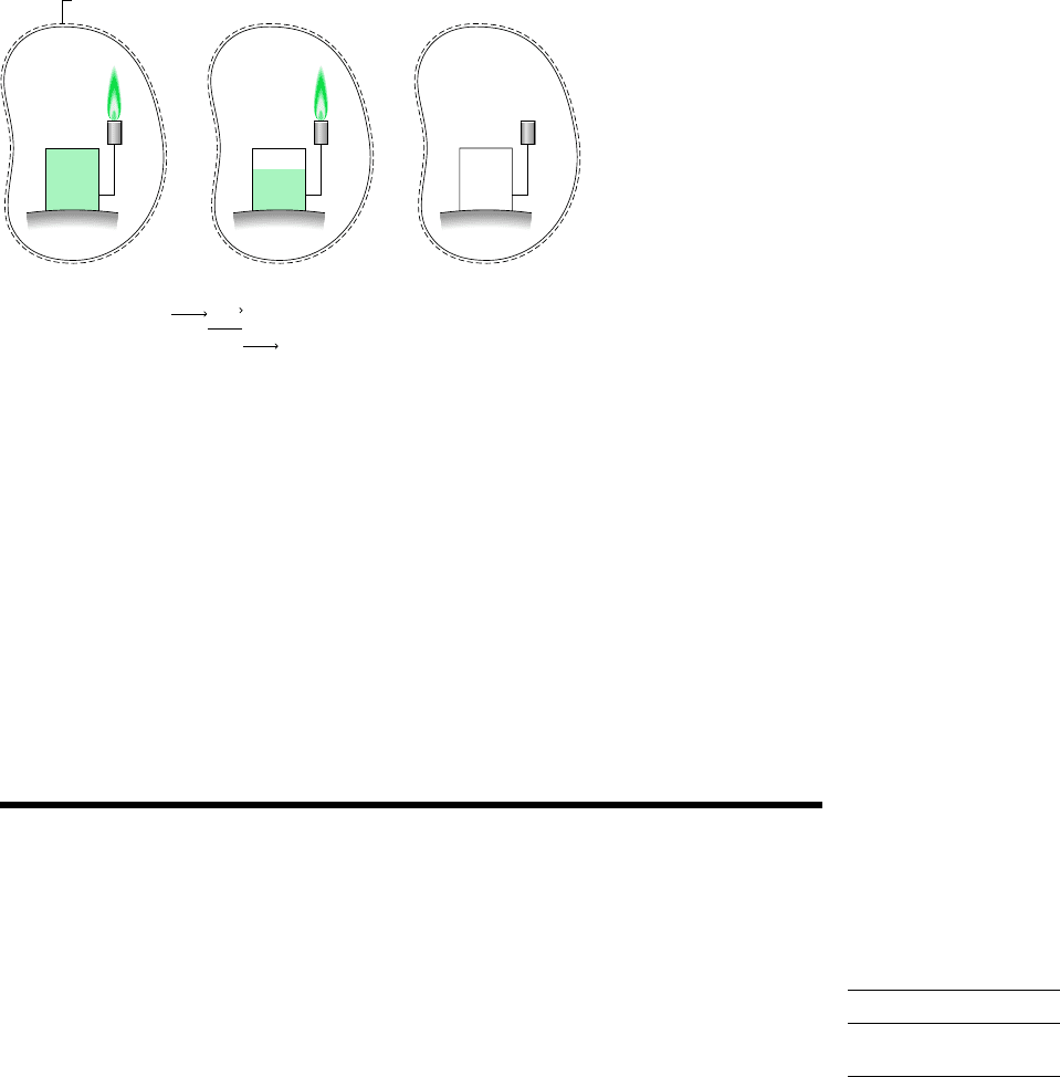
for example. . . Figure 7.1a shows an isolated system consisting initially of a small
container of fuel surrounded by air in abundance. Suppose the fuel burns (Fig. 7.1b) so that
finally there is a slightly warm mixture of combustion products and air as shown in Fig. 7.1c.
Although the total quantity of energy associated with the system would be unchanged, the
initial fuel–air combination would have a greater economic value and be intrinsically more
useful than the final warm mixture. For instance, the fuel might be used in some device to
generate electricity or produce superheated steam, whereas the uses to which the slightly
warm combustion products can be put would be far more limited in scope. We might say that
the system has a greater potential for use initially than it has finally. Since nothing but a final
warm mixture would be achieved in the process, this potential would be largely wasted. More
precisely, the initial potential would be largely destroyed because of the irreversible nature
of the process.
7.2 Defining Exergy 273
Anticipating the main results of this chapter, we can read exergy as potential for use
wherever it appears in the text. The foregoing example illustrates that, unlike energy,
exergy is not conserved.
Subsequent discussion shows that exergy not only can be destroyed by irreversibilities but
also can be transferred to a system or from a system, as in losses accompanying heat trans-
fers to the surroundings. Improved resource utilization can be realized by reducing exergy
destruction within a system and/or losses. An objective in exergy analysis is to identify sites
where exergy destructions and losses occur and rank order them for significance. This allows
attention to be centered on the aspects of system operation that offer the greatest opportunities
for improvement.
7.2 Defining Exergy
The basis for the exergy concept is present in the introduction to the second law provided in
Chap. 5. A principal conclusion of Sec. 5.1 is that an opportunity exists for doing work when-
ever two systems at different states are brought into communication. In principle, work can
be developed as the systems are allowed to come into equilibrium. When one of the two sys-
tems is a suitably idealized system called an exergy reference environment or simply, an
environment, and the other is some system of interest, exergy is the maximum theoretical
work obtainable as they interact to equilibrium.
The definition of exergy will not be complete, however, until we define the reference
environment and show how numerical values for exergy can be determined. These tasks are
closely related because the numerical value of exergy depends on the state of a system of
interest, as well as the condition of the environment.
7.2.1 Exergy Reference Environment
Any system, whether a component of a larger system such as a steam turbine in a power
plant or the larger system itself (power plant), operates within surroundings of some kind. It
is important to distinguish between the environment used for calculating exergy and a sys-
tem’s surroundings. Strictly speaking, the term surroundings refers to everything not included
in the system. However, when considering the exergy concept, we distinguish between the
Fuel
Air at temperature
T
i
Fuel
Time
(a)(b)(c)
Air and combustion
products at
temperature T
i
+ dT
Boundary of the
isolated system
Energy quantity constant
Potential for use decreases
Figure 7.1 Illustration used to introduce exergy.
exergy reference
environment
exergy
274 Chapter 7 Exergy Analysis
Figure 7.2
Schematic of a power plant and its surroundings.
Immediate surroundings–intensive
properties may vary in interactions
with power plant
Stack
gases
Fuel
Cooling water in
Boundary of plant
PowerPower
Cooling water out
Delineates the
immediate plant
surroundings from
the environment
Intensive properties of this portion
of the surroundings are not affected
by any process within the power plant
or its immediate surroundings
Environment –
Air
River or other body
of water – the portion
not interacting with
the power plant would
be in the environment
immediate surroundings, where intensive properties may vary during interactions with the
system, and the larger portion of the surroundings at a distance, where the intensive proper-
ties are unaffected by any process involving the system and its immediate surroundings. The
term environment identifies this larger portion of the surroundings.
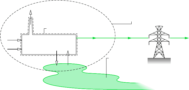
for example. . . Fig. 7.2 illustrates the distinction between a system consisting
of a power plant, its immediate surroundings, and the environment. In this case, the
environment includes portions of the surrounding atmosphere and the river at a distance
from the power plant. Interactions between the power plant and its immediate surround-
ings have no influence on the temperature, pressure, or other intensive properties of the
environment.
MODELING THE ENVIRONMENT
The physical world is complicated, and to include every detail in an analysis is not practical.
Accordingly, in describing the environment, simplifications are made and a model results.
The validity and utility of an analysis using any model are, of course, restricted by the
idealizations made in formulating the model. In this book the environment is regarded to
be a simple compressible system that is large in extent and uniform in temperature, T
0
, and
pressure, p
0
. In keeping with the idea that the environment represents a portion of the
physical world, the values for both p
0
and T
0
used throughout a particular analysis are nor-
mally taken as typical environmental conditions, such as 1 atm and 25C. The intensive
properties of each phase of the environment are uniform and do not change significantly
as a result of any process under consideration. The environment is also regarded as free of
irreversibilities. All significant irreversibilities are located within the system and its imme-
diate surroundings.
Although its intensive properties do not change, the environment can experience changes
in its extensive properties as a result of interactions with other systems. Changes in the
extensive properties internal energy U
e
, entropy S
e
, and volume V
e
of the environment are
7.2 Defining Exergy 275
related through the first T dS equation, Eq. 6.10. Since T
0
and p
0
are constant, Eq. 6.10 takes
the form
(7.1)
In this chapter kinetic and potential energies are evaluated relative to the environment, all
parts of which are considered to be at rest with respect to one another. Accordingly, as indi-
cated by the foregoing equation, a change in the energy of the environment can be a change
in its internal energy only. Equation 7.1 is used below to develop an expression for evaluat-
ing exergy. In Chap. 13 the environment concept is extended to allow for the possibility of
chemical reactions, which are excluded from the present considerations.
7.2.2 Dead State
Let us consider next the concept of the dead state, which is also important in completing our
understanding of the property exergy.
If the state of a fixed quantity of matter, a closed system, departs from that of the envi-
ronment, an opportunity exists for developing work. However, as the system changes state
toward that of the environment, the opportunity diminishes, ceasing to exist when the two
are in equilibrium with one another. This state of the system is called the dead state. At the
dead state, the fixed quantity of matter under consideration is imagined to be sealed in an
envelope impervious to mass flow, at rest relative to the environment, and internally in equi-
librium at the temperature T
0
and pressure p
0
of the environment. At the dead state, both the
system and environment possess energy, but the value of exergy is zero because there is no
possibility of a spontaneous change within the system or the environment, nor can there be
an interaction between them.
With the introduction of the concepts of environment and dead state, we are in a position
to show how a numerical value can be determined for exergy. This is considered next.
7.2.3 Evaluating Exergy
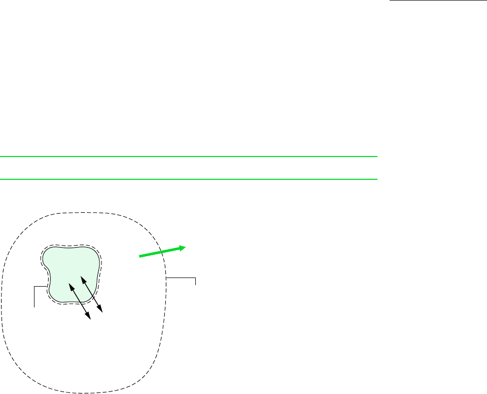
The exergy of a system, E, at a specified state is given by the expression
(7.2)E 1E U
0
2 p
0
1V V
0
2 T
0
1S S
0
2
¢U
e
T
0
¢S
e
p
0
¢V
e
dead state
exergy of a system
Boundary of
the combined
system.
Heat and work
interactions with
the environment
System
boundary
Environment at T
0
, p
0
W
c
Closed
system
Figure 7.3 Combined system
of closed system and environment.
