Middleton W.M. (ed.) Reference Data for Engineers: Radio, Electronics, Computer and Communications
Подождите немного. Документ загружается.


46-1
6
REFERENCE
DATA
FOR ENGINEERS
0.05
-
-
E
0'04
1
$
e
11
0.03
-
s
z
-
0.02
-
1-0
-
0.01
-
1
I I I
1
I
10
20
30
40
50
/VIA)
1
I
I
I
I
I
I
-20
-15
-10
-5
0
5
10
SIGNAL
LEVEL
IN
dB
WH
RESPECT
TO
rms
VALUES
Fig.
10.
Average duration of fades.
CELLULAR TELECOMMUNICATIONS SYSTEMS
46-1
7
u=
T/f
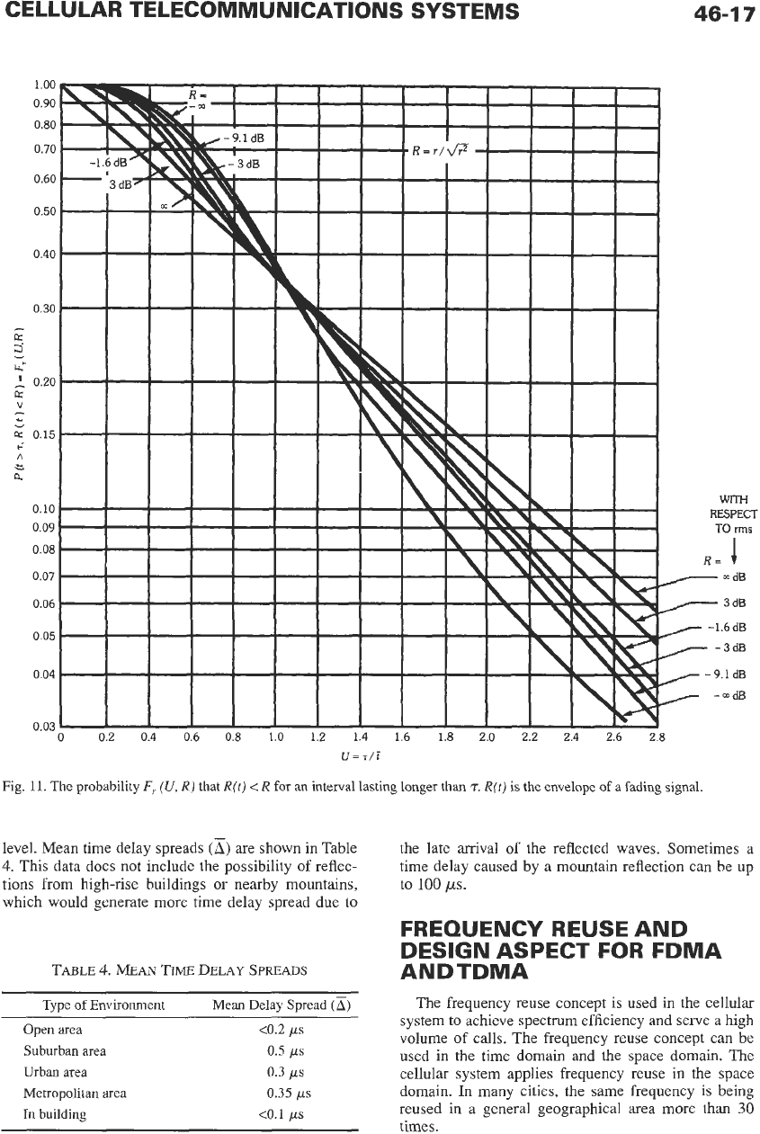
Fig.
11.
The
probability
F,
(U,
RJ
that
R(t)
<
R
for an interval lasting longer
than
T.
R(tj
is
the envelope of
a
fading signal
level. Mean time delay spreads
(a)
are shown in Table
4.
This data does not include the possibility
of
reflec-
tions from high-rise buildings or nearby mountains,
which would generate more time delay spread due to
the late arrival
of
the reflected waves. Sometimes a
time delay caused by a mountain reflection can be up
to
100
ps.
FREQUENCY REUSE AND
DESIGN ASPECT FOR FDMA
ANDTDMA
TABLE
4.
MEAN
TIME
DELAY SPREADS
Type of Environment Mean
Delay
Spread
(a)
The frequency reuse concept is used in the cellular
system
to
achieve spectrum efficiency and serve a high
volume of calls. The frequency reuse concept can be
used in the time domain and the space domain. The
cellular system applies frequency reuse in the space
domain.
In
many cities, the same frequency is being
reused in
a
general geographical area more than
30
Open
area
<0.2
ps
Suburban
area
0.5
ps
Urban
area
0.3
ps
Metropolitan
area
0.35
ps
In
building
<0.1
us
u
times.

46-1
8
REFERENCE
DATA
FOR ENGINEERS
Frequency Reuse Distance
When the same channel is
to
be reused in two cells,
the two cells are called cochannel cells. The distance
D
is the separation of the two cochannel cells. The smaller
the
D,
the greater the spectrum efficiency would be. The
key parameter, a ratio of
DiR,
where
R
is
the cell radius,
is
used
to
measure the spectrum efficiency.
Cellular Design Aspect
The cellular system is a high-capacity and spec-
trum-efficient system. In the
AMPS
system, it
was
found from subjective tests that
75%
of
the people
grade the system voice quality as “good” or “excel-
lent” at the system’s required carrier-to-interference
ratio
(C/o,
t
18
dB (which is
63
in
a linear scale). The
level of
C/I
=
18
dB will be set at the boundary
of
the
cell as shown in Fig.
12.
The
DIR
ratio is obtained
based
on
the six cochannel cells surrounding the cell
of interest, and the mobile radio propagation rule of
40
dB/decade. Furthermore, assume for simplicity that all
the
Ds
are equal. Then
Fig. 12.
Six
effective
interfering
cells
of
cell
1
CELLULAR TELECOMMUNICATIONS
SYSTEMS
46-1
9
or
(DIR),
=
4.4
The computer simulation finds
a
required value of
(DiR),
=
4.6, which
is
slightly different from the value
of 4.4 which was generated from Eq.
5.
The
(DiR),
ratio can be called Cochannel Interference Reduction
Factor (CIRF),
q,
4
=
(D/R),
(Eq. 6)
In designing a cellular system, the key factor is
q
Frequency Reuse Factor,
K
The factor
q
can be related to
a
finite set of cells in a
frequency reuse pattern. K is
a
frequency reuse factor
calculated in a hexagonal-shaped cellular system by
q=a
or K=q2/3 (Eq.
7)
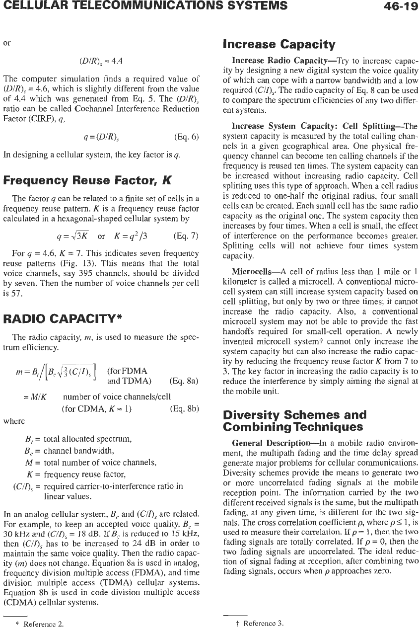
For
q
=
4.6,
K
=
7.
This indicates seven frequency
reuse patterns (Fig. 13). This means that the total
voice channels, say 395 channels, should be divided
by seven. Then the number of voice channels per cell
is
57.
RADIO CAPACITY*
The radio capacity,
m,
is used
to
measure the spec-
trum efficiency.
m
=
Bl/[..
dm]
(for FDMA
and TDMA) (Eq. 8a)
=
MIK
number of voice channels/cell
(for CDMA, K
=
1)
(Eq. sb)
where
B,
=
M=
K=
B,
=
(ems
=
total
allocated spectrum,
channel bandwidth,
total number of voice channels,
frequency reuse factor,
required carrier-to-interference ratio in
linear values.
In an analog cellular system,
B,
and
(Cir),
are related.
For example,
to
keep an accepted voice quality,
B,
=
30
kHz
and
(C/os
=
18
dJ3.
VB,
is reduced to
15
kHz,
then
(C/o,
has
to
be increased
to
24 dB in order to
maintain the same voice quality. Then the radio capac-
ity
(m)
does
not
change. Equation
8a
is used in analog,
frequency division multiple access (FDMA), and time
division multiple access (TDMA) cellular systems.
Equation 8b is used
in
code division multiple access
(CDMA) cellular systems.
*
Reference
2.
Increase Capacity
Increase Radio Capacity-Try to increase capac-
ity by designing
a
new digital system the voice quality
of which can cope with
a
narrow bandwidth and a
low
required
(CIZ),.
The radio capacity of Eq.
8
can be used
to compare the spectrum efficiencies of any two differ-
ent systems.
Increase System Capacity: Cell Splitting-The
system capacity is measured by the total calling chan-
nels in a given geographical area. One physical fre-
quency channel can become ten calling channels if the
frequency is reused ten times. The system capacity can
be increased without increasing radio capacity. Cell
splitting uses this type of approach. When a cell radius
is reduced
to
one-half the original radius, four small
cells can be created. Each small cell
has
the same radio
capacity
as
the original one. The system capacity then
increases by four times. When a cell is small, the effect
of interference
on
the performance becomes greater.
Splitting cells will not achieve four times system
capacity.
Microcells-A cell of radius less than 1 mile or 1
kilometer is called
a
microcell.
A
conventional micro-
cell system can still increase system capacity based
on
cell splitting, but only by two or three times; it cannot
increase the radio capacity. Also, a conventional
microcell system may
not
be able
to
provide the fast
handoffs required for small-cell operation. A newly
invented microcell system? cannot only increase the
system capacity but can
also
increase the radio capac-
ity by reducing the frequency reuse factor K from
7
to
3.
The key factor in increasing the radio capacity is
to
reduce the interference by simply aiming the signal at
the mobile unit.
Diversity Schemes and
Co
m
b
i
n
i
ng Tech n
i
q u es
General Description-In
a
mobile radio environ-
ment, the multipath fading and the time delay spread
generate major problems for cellular communications.
Diversity schemes provide the means
to
generate
two
or
more uncorrelated fading signals at the mobile
reception point. The information carried by the two
different received signals is the same, but the multipath
fading, at any given time, is different for the two sig-
nals. The cross correlation coefficient
p,
where
p
I
1,
is
used
to
measure
their
correlation.
If
p
=
1,
then
the
two
fading signals are totally correlated. If
p
=
0,
then the
two
fading signals are uncorrelated. The ideal reduc-
tion of signal fading at reception, after combining
two
fading signals, occurs when
p
approaches zero.
-
t
Reference
3.
46-20
REFERENCE
DATA
FOR ENGINEERS
K=4
12
CELL REUSE PATERN
TO
START
UP CONFIGURATION
Fig.
13.
N-cell
reuse
patterns.
SHIFr
PARAMETERS
i
=
3,
j
=
2
Diversity Schemes-There are six common diver-
2.
Field component diversity (receives
E
field and
H
sity schemes,
as
follows: field)
3.
Polarization diversity (receives vertically and hor-
1.
Space diversity (receives two fading signals from
izontally polarized waves,
or
left-hand and right-
hand circularly polarized waves)
two
separate antennas)
CELLULAR TELECOMMUNICATIONS SYSTEMS
46-2
1
4.
Time diversity (repeats the same signal more than
5.
Frequency diversity (receives two fading signals
6.
Angle diversity (receives two fading signals from
Combining Techniques-There are three general
techniques for combining two or more uncorrelated or
partially correlated received fading signals. The signal
fading is reduced after combination. The best method
is the maximum-ratio combiner, which combines the
signals to achieve the maximum signal-to-noise ratio.
The next best technique is the equal-gain combiner. It
combines the two fading signals in phase to reduce the
signal fading. The third technique
is
the selective com-
biner. This technique always selects the strongest sig-
nal from among the received fading signals. The
difference in performance between the maximum-ratio
technique and the selective-combiner technique is
2
dB. The switched combined technique which switches
the signal when it is below
a
threshold level is not
applicable
in
cellular systems.
Antenna Separation Requirement-At
the Base
Station:
The antenna separation for cellular systems is
determined by the formula
once)
on
two different frequencies)
two different directions)
hid=
11
where
h
is the antenna height,
d
is the spacing between two antennas.
If
h
=
30
m, then
d
=
2.72
m. The formula does
not
apply if the location
of
a mobile unit is in line with the
two base-station antennas. Therefore, the orientation
of two antennas mounted
on
a mast has
to
be carefully
determined
to
obtain the maximum diversity gain in
the
cell.
At the Mobile Unit:
A separation of a half wave-
length between two mobile antennas is required at
850
MHz.
Therefore, the separation between two antennas
needs to be only
0.18
m (about
6
inches) at the cellular
frequency of
850
MHz.
Diversity Scheme Reduces Time Delay Spread-
The diversity scheme not only reduces the signal fad-
ing, it also reduces the time delay spread. Time delay
spread does not affect an analog system, but it does
affect
a
digital system. The time delay spread in a
mobile radio environment always exists at the recep-
tion point whether the mobile unit
is
standing still
or
moving. Signal fading occurs
only
when the mobile
unit
is moving.
In
a digital system,
an
equalizer is nor-
mally used to reduce the intersymbol interference
which is caused by the time delay spread. The strength
of the equalizer equipment is based
on
the severity
of
the mobile radio environment. When the diversity
scheme has been implemented, the equalizer design
requirement can be relaxed or removed.
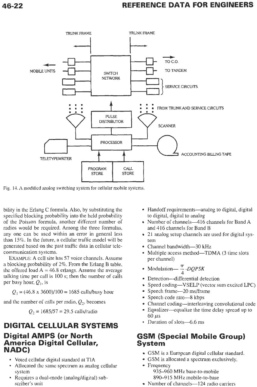
SWITCHING EQUIPMENT AND
TRAFFIC MODELS
Analog Switching Equipment
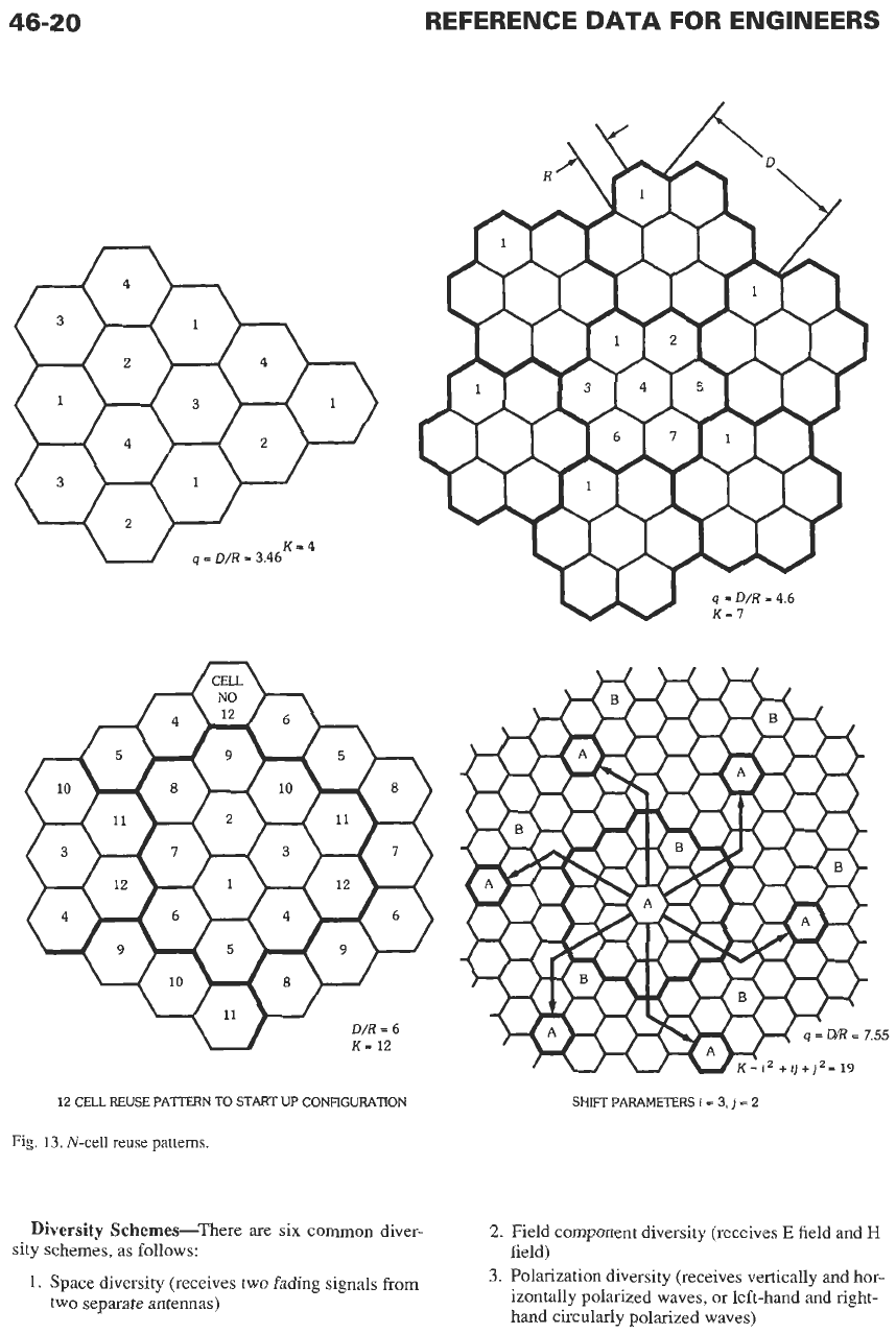
The analog switch is usually a circuit switch which
must hold a call throughout the duration of the call.
The analog switching equipment consists of processor,
memory, switching network,
trunk
circuitry, and mis-
cellaneous service circuitry
as
shown in Fig. 14. The
switching of a Class
5
telephone central office is
switching from trunk frame to line frame. The differ-
ence in this cellular switching equipment is the switch-
ing from trunk frame to trunk frame via the switch
network. One trunk side is connected to the mobile
calls because the mobile unit does not have a fixed fre-
quency channel associated with a mobile unit. The
other trunk side is connected
to
PSTN.
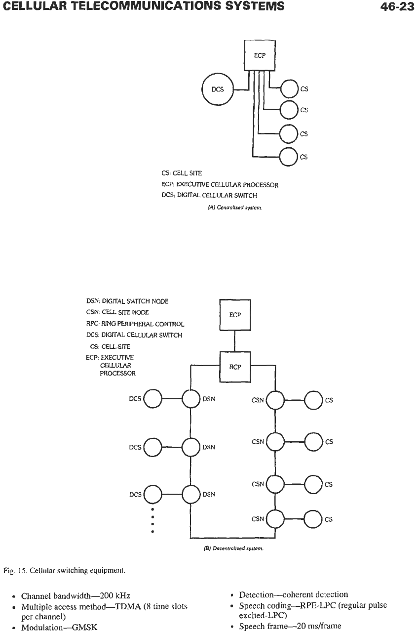
Cellular
Digital Switching
Equipment
The digital switch is usually
a
message switch han-
dling digitized messages. The digital switch can send
the message or transmit the voice in digital form.
Therefore, the digital signal format permits breaking a
message into small pieces for faster transmission.
Also, it can handle other calls while the switch alter-
nates between the
“on”
and “off’ modes periodically.
Hence, the call-processing efficiency of digital switch-
ing is higher than that of analog switching. The other
advantages of using
a
digital switch are small size, less
power consumption, less human effort required
to
operate, and ease of maintenance. Digital switching
equipment can be modular and is very flexible. Often,
capacity can be increased simply by adding modules.
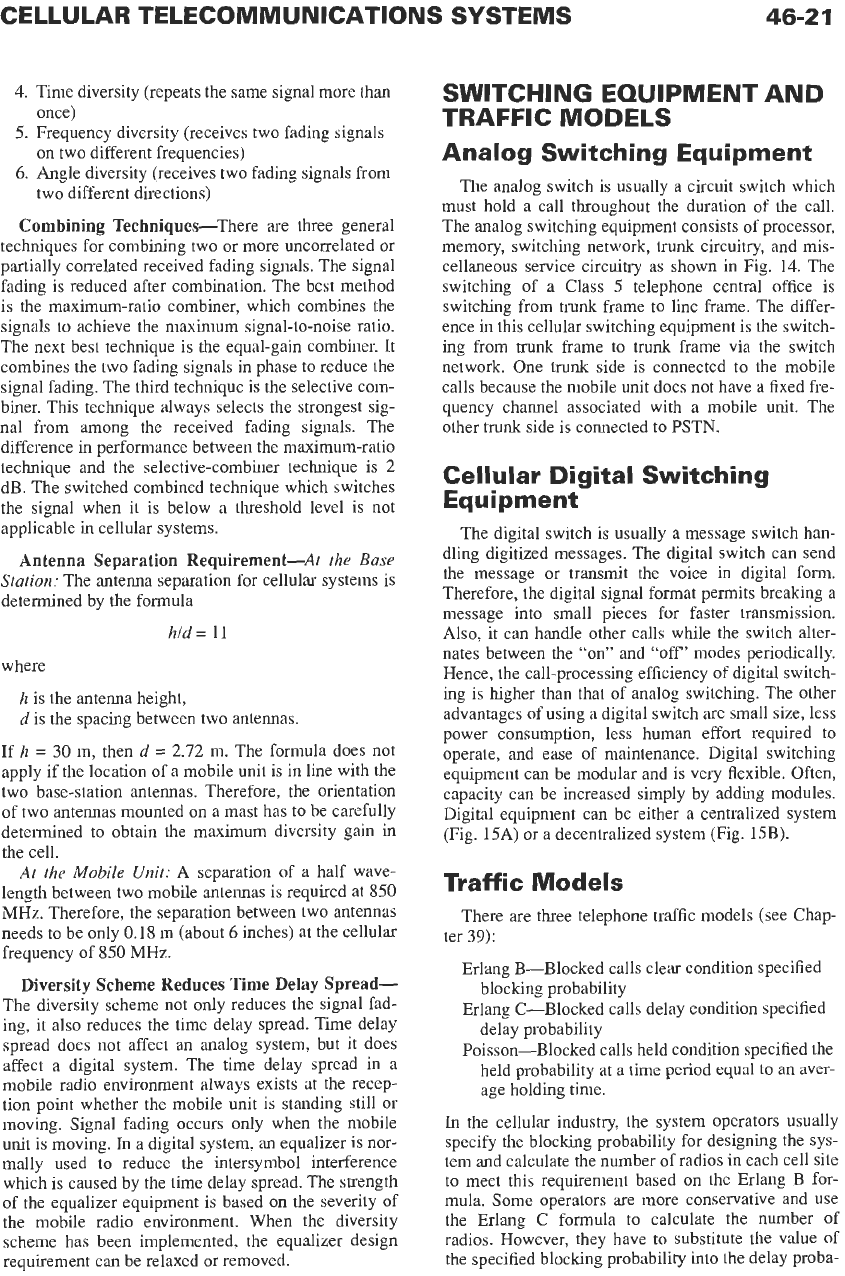
Digital equipment can be either a centralized system
(Fig. 15A) or a decentralized system (Fig.
15B).
Traffic
Models
There are three telephone traffic models (see Chap-
Erlang B-Blocked calls clear condition specified
blocking probability
Erlang C-Blocked calls delay condition specified
delay probability
Poisson-Blocked calls held condition specified the
held probability
at
a
time period equal
to
an
aver-
age holding time.
In
the cellular industry, the system operators usually
specify the blocking probability for designing the sys-
tem and calculate the number of radios
in
each cell site
to meet this requirement based
on
the Erlang B for-
mula. Some operators are more conservative and use
the
Erlang C formula to calculate the number of
radios. However, they have to substitute the value
of
the specified blocking probability into the delay proba-
ter
39):
46-22
PROGRAM CALL
STORE STORE
TRUNK FRAME TRUNK FRAME
I-
*
MOBILE UNITS
-
---t
--
TO C.O.
-
-
-
TO
TANDEM
d
SWCH
SERVICE CIRCUITS
NETWORK
FROM TRUNK AND SERVICE CIRCUITS
SCANNER
ACCOUNTING BILLING TAPE
Fig.
14.
A
modified
analog switching
system
for
cellular
mobile
systems.
bility in the Erlang
C
formula. Also, by substituting the
specified blocking probability into the held probability
of the Poisson formula, another different number of
radios would be required. Among the three formulas,
any one can be used within an error in general less
than 15%. In the future,
a
cellular traffic model will be
generated based on the past traffic data in cellular tele-
communication systems.
EXAMPLE:
A
cell site has 57 voice channels. Assume
a
blocking probability of 2%. From the Erlang B table,
the offered load A
=
46.8 erlangs. Assume the average
talking time per call is
100
s;
then the number of calls
per busy hour,
Q,, is
Q,
=
(46.8
x
3600)/100
=
1685 calls/busy hour
and the number
of
calls per radio,
Q2,
becomes
Q2
=
1685/57
=
29.5 calls/radio
DIGITAL CELLULAR SYSTEMS
Digital AMPS (or North
America Digital Cellular,
NADC)
*
Voted cellular digital standard at TIA
-
Allocated the same spectrum as analog cellular
system
*
Requires
a
dual-mode (analog/digital) sub-
scriber’s unit
Handoff requirements-analog to digital, digital
to digital, digital to analog
Number of channels416 channels for Band A
and 416 channels for Band
B
21 analog setup channels
are
used for digital sys-
tem
Channel bandwidth-30
kHz
Multiple access method-TDMA (3 time
slots
per channel)
T
Modulation-
-
-DQPSK
4
Detection-differential detection
Speed coding-VSELP (vector sum excited LPC)
Speech frame-20 ms/frame
Speech code rate-8 kbps
Channel coding-interleaving convolutional code
Equalizer-equalize the time delay spread up to
-
Duration of slots-6.6 ms
60
ps
GSM (Special Mobile Group)
System
GSM is
a
European digital cellular standard.
GSM is allocated
a
spectrum exclusively.
Frequency
935-960 MHz base-to-mobile
890-915 MHz mobile-to-base
Number
of channels-124 radio carriers
CELLULAR TELECOMMUNICATIONS SYSTEMS
0
cs
CS: CELL
SITE
ECP: EXECUTIVE CELLULAR PROCESSOR
DCS: DIGITAL CELLULAR SWITCH
(A)
Centrollzed
system.
DSN: DIGITAL SWITCH NODE
CSN: CELL
SITE
NODE
RPC: RING PERIPHERAL CONTROL
DCS:
DIGITAL CELLULAR SWITCH
CS:
CELL
SITE
ECP: EXECUTIVE
CELLULAR
PROCESSOR
An
DCS
46-23
cs
cs
cs
CSN CS
(BJ
Decentrollzed
system.
Fig.
15. Cellular
switching equipment.
Channel bandwidth-200
WZ
Multiple access method-TDMA
(8
time slots
Modulation-GMSK
per channel)
Detection-coherent detection
Speech coding-WE-LPC
(regular
pulse
Speech frame-20 ms/frame
excited-LPC)
46-24
REFERENCE
DATA
FOR ENGINEERS
Speech coding rate-13 kbps
Channel coding-convolutional code
Equalizer-equalize the time delay spread up to
16
ps
Transmission rate-270 kbps
Duration of slots-0.557 ms (the frame of 8 slots
is 4.615 ms)
Cellular CDMA System
This is a code division multiple access (CDMA)
system.
CDMA is in the process
of
being standardized by
TIA.
Bandwidth-1.23 MHz
Modulation-BPSK
Eb/Io
=
7 dB
Speech coding rate-8 kbps (variable rate for
nonvoice conditions)
Power control increment-0.5 dB
Channel coding-convolutional code
Detection-Forward channel uses coherent detec-
tion; reverse channel uses noncoherent detection.
Transmit power
cell site-1.25 W
mobile-300 mW
Range-13 miles
36
Systems
Three modes are FDD direct spread, FDD multicar-
rier, and TDD as listed in Table 2.
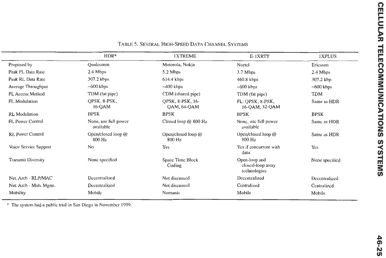
In FDD modes, several high-speed data channel sys-
tems have been introduced as shown in Table
5.
Depending
on
different modulations, the peak data rate
can be from a range of 2.4 to 5.2 Mbps.
46
System
A TDD system with a set
of
smart code (LAS code)4
can reduce the multiuser access interference and the
multi-path interference along a single-spectrum band
transmission. It brings a high hope that using a code
technology to change the system environment from an
interference environment to a noise environment is a
winner for the 4G system.
Other Personal
Com m
u
n icat ion Systems
PCN (Personal Communication Network)
Three licenses
in
UK
Frequency-50-100 MHz band in 1.8 GHz range
System-modified GSM
DECT (Digital European Cordless Telephone)
Frequency-1 880-1 900 MHz
Multiple access-TDMA/TDD
Transmission rate-38.8 kbps/slot channel
Modulation-GFSK
Channel bandwidth-1.728 MHz/channel
TDD (Time division duplex)
12 slots (base-to-portable)
12 slots (portable-to-base)
Frame length-10 ms/24 time slots
Number
of
channels-5
Transmit power-10 mW
CT-2 (Cordless Telephone-2)
This system acts as a “portable payphone booth”
Applied country-four licenses issued in UK
Transmission signal format-TDD (time division
duplexing)
Number of channels40
Channel bandwidth-100 kHz/TDD channel
No call delivery capability
No handoffs
REFERENCES
1. Lee, W. C.
Y.
“Lee’s Model,”
IEEE Transactions
on
Vehicular Technology,
Feb. 1988, pp. 69-71.
Also
in
Chapter 4 of
Mobile Cellular Telecommu-
nications Systems.
McGraw-Hill, 1989.
2. Lee, W. C.
Y.
“Spectrum Efficiency in Cellular.”
IEEE Transactions
on
Vehicular Technology,
May
3. Lee, W. C.
Y.
“A New Microcell Architecture.”
IEEE Communications Magazine,
Nov. 1991, pp.
4.
Lee, W. C.
Y.
Lee’s Essentials
of
Wireless Commu-
1989, pp. 69-75.
19-23.
nications.
McGraw-Hill, 2001, p. 289
BIBLIOGRAPHY
1.
2.
3.
4.
5.
6.
7.
8.
9.
Bell Laboratories.
High Capacity Mobile Tele-
phone System Technical Report.
Dec. 1971, sub-
mitted to the FCC.
Blecher,
E
H.
“Advanced Mobile Phone Service.”
IEEE Transactions
on
Vehicular Technology,
Vol.
VT-29, May 1980, pp. 238-244.
Bell System Technical Journal,
special issue
on
“Advanced Mobile Phone Service (AMPS),” Vol.
58, Jan. 1979.
EIA Interim Standard,
Cellular System Mobile
Station-Land Station Compatibility Specification,
TIA Interim Standard, IS-54,
Digital Cellular Sys-
tem Mobile Station-Land Station Compatibility
Specification,
Jan., 1990.
TIA Interim Standard, IS-55,
Digital Cellular Sys-
tem Mobile Station Specification.
Jan. 1991.
TIA Interim Standard, IS-56,
Digital Cellular Sys-
tem Land Station Specification.
Jan. 1991.
GSM-European Digital Cellular Standard.
Qualcomm Presentation at CTIA, “Cellular
CDMA,” July 21, 1991.
IS-3-D EIA. March 1987.
T
BLE
5.
SEVER
HIGH-SPEED
DATA CHI
NEL
SYSTEMS
HDR*
1xTREME
E-1XRlT
1xFJLUS
Ericsson
Proposed by
Qualcomm
Motorola, Nokia Nortel
Peak
FL
Data Rate 2.4 Mbps
5.2 Mbps
3.7 Mbps 2.4 Mbps
Peak
RL
Data Rate 307.2 kbps
614.4 kbps
460.8 kbps 307.2 kbp
Average Throughput
-600
kbps
-400 kbps
-600 kbps -600 kbps
F'L
Access
Method TDM (fat pipe)
CDM (shared pipe) TDM (fat pipe) TDM
Same
as
HDR
FL
Modulation QPSK, 8-PSK, QPSK, 8-PSK, 16-
FL:
QPSK, 8-PSK,
16-QAM QAM, 64-QAM 16-QAM, 32-QAM
RL
Modulation BPSK BPSK BPSK BPSK
FL
Power Control None,
use
full power Closed loop
@
800 Hz None, use full power
Same
as HDR
Same as HDR
RL
Power Control Open/closed loop
@
Open/closed loop
@
Voice Service Support No
Yes
Yes if concurrent with Yes
Transmit Diversity None specified
available available
800 Hz 800 Hz 800 Hz
Open/closed loop
@
data
Space Time Block Open-loop and None specified
Coding closed-loop array
technologies
Net. Arch
-
RLP/MAC
Decentralized
Not discussed
Decentralized
Decentralized
Net. Arch
-
Mob. Mgmt.
Decentralized
Not discussed
Centralized
Centralized
Mobility Mobile Nomanic
Mobile
Mobile
*
The system had a public trial in
San
Diego in November 1999.
P
h)
Q
Q