Middleton W.M. (ed.) Reference Data for Engineers: Radio, Electronics, Computer and Communications
Подождите немного. Документ загружается.

38
Common Carrier
Transmission
Revised
by
Ludwell Sibley
The Switched Telecommunications System
38-3
Conventional Voiceband Service
Integrated Services Digital Network Service
The Exchange Plant
38-3
Subscriber Sets
Subscriber Loops
Local Interoffice Trunks
The Toll Transmission Plant
38-6
Exchange-Access Trunks
Intertoll Trunks
Digital Subscriber Line
38-7
IDSL
ADSL
ADSL “Lite”
RADSL
VDSL
HDSL
SDSL
International Recommendations
38-8
Overall System Design
Loss
Echo Control
38-1
38-2
REFERENCE
DATA
FOR ENGINEERS
Quality Objectives and Definitions
38-9
Noise
Levels and Loss
Echo and Stability
Crosstalk
Digital Performance
Facilities
38-11
Wire
Repeaters
Four-Wire Repeaters
Hybrid Repeaters
Fiber-optic Facilities
Carrier Systems
Network-Control Signaling
38-1
6
Subscriber-Loop Signaling
Interoffice Signaling
COMMON CARRIER TRANSMISSION
38-3
THE SWITCHED
TELECOMMUNICATIONS
SYSTEM
The telecommunications system combines many
elements that work together
to
provide a variety of ser-
vices. It is a network of networks, owned and operated
by multiple parties.
In
this section we consider two
applications of the switched network: voice service
and ISDN, and a special case, the Digital Subscriber
Line.
Conventional Voiceband
Service
Switched voiceband connections for speech or data
use (including facsimile and data approaching
56
kb/s)
are set up by giving appropriate instructions from the
subscriber’s telephone set or other terminal. Every
subscriber
is
connected to
a
local end-office switching
system via a loop; consequently, there is a loop at each
end of a switched connection. To connect between
loops served by different end offices, it is necessary
to
use a trunk route.
The route may be a single trunk connected directly
between end-office switching systems. Other local
trunks
provide access
to
and from “wireless” carriers
for cellular-mobile, paging, and similar services; to a
Public Safety Answering Point for “911” emergency
service; or to an Internet Service Provider
(ISP).
Alternatively, the trunk route may consist
of
several
trunks routed through one or more tandem switching
systems. Such a call may involve
trunks
between the
switching facilities of exchange and interexchange car-
riers (domestically) or of different operating adminis-
trations (internationally). Direct
trunks
and
hunks
to
tandem switching systems are generally limited to the
exchange area, covering tens of miles or occasionally a
few hundred miles. When a connection must be made
over greater distances, the
trunk
route passes through
toll-connecting and intertoll trunks and is switched by
toll switching systems in accordance with a routing
plan which is usually dynamically controlled accord-
ing
to
traffic load.
As a matter of terminology, the local end office is
commonly referred to as a “Class
5”
office. This iden-
tification is a remainder of a one-time switching plan
that used a hierarchy of toll switching offices, up
through
“Class
1.”
The hierarchy has been replaced by
a plan in which all toll switching offices have essen-
tially equal rank, but the “Class
5”
office remains.
Integrated Services Digital
Network Service
ISDN is a multi-use network in which wholly digital
transmission is provided between customer locations,
with digital telephones and data terminals being used.
Access from the subscriber
to
the serving central office
is defined in terms of “B” channels
(64
kb/s each) and
“D’
channels (16 or
64
kb/s). The
“B”
channels carry
voice, data, and video traffic in digital form, while the
subscriber controls service (signaling and supervision)
via a two-way message link on the “D” channel. There
may be two “B” channels and one “D” (in basic-rate
access) or 23 “B” channels and one “D” (in primary-
rate access).
Digital connections are established in a way compa-
rable to that for conventional voice service. Pairs or
multiples of “B” channels may be used (“bonded”)
together for 128 kb/s
or
higher speeds.
The following material gives information about the
various transmission elements (e. g., loops and trunks)
and about the signaling systems used to set up, hold,
and disconnect the channels.
THE EXCHANGE PLANT
Subscriber Sets
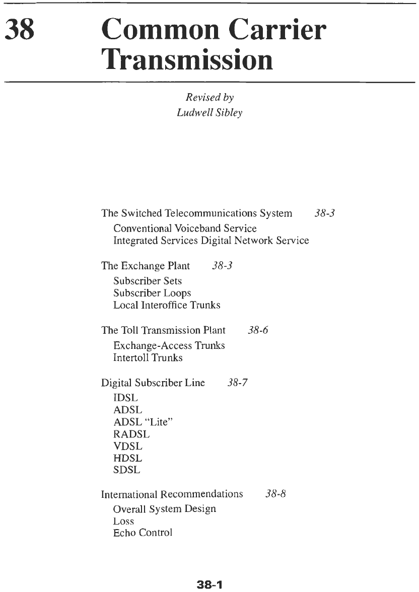
The 500-type subscriber set is the historical basis
for standards for analog subscriber instruments
(ANSI/
TIA/EIA-470-B-97), even though later telephones are
usually designed quite differently. Fig.
1
illustrates
transmission performance of a 500-type set
on
two
hypothetical connections involving relatively short and
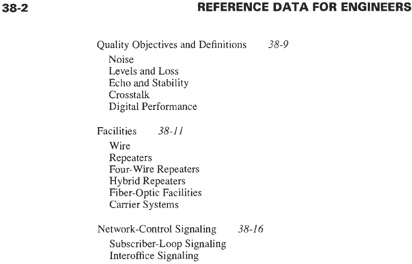
relatively long loops. Fig. 2 shows the test configura-
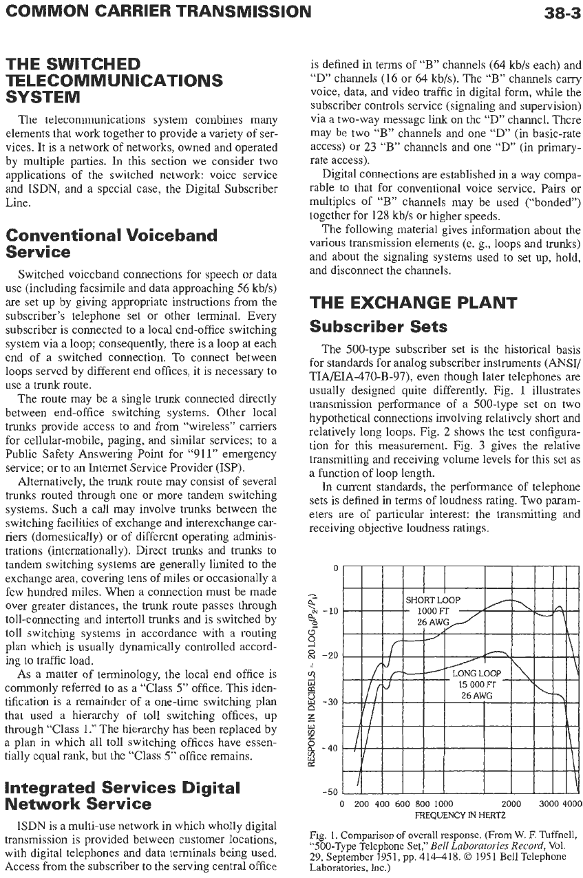
tion for this measurement. Fig. 3 gives the relative
transmitting and receiving volume levels for this set as
a function of loop length.
In current standards, the performance of telephone
sets
is
defined in terms of loudness rating. Two param-
eters are of particular interest: the transmitting and
receiving objective loudness ratings.
0
-
6
%
-10
e
2
a
s
::
-20
/I
m
8
-30
n
z
u)
m
z
2
-40
2
-50
2000
3000
4000
0
200
400
600
800
1000
FREQUENCY
IN
HERTZ
Fig.
1. Comparison
of
overall
response.
(From
W.
E
Tuffnell,
“500-Type Telephone
Set,”
Bell Laboratories Record,
Vol.
29,
September 1951, pp. 414418.
0
1951 Bell Telephone
Laboratories,
Inc.)
38-4
REFERENCE
DATA
FOR ENGINEERS
-
-
TELEPHONE 26-AWG
SW~TCH
SWITCH
Pl SET LOOP
-
-
-
-
26-AWG TELEPHONE
LOOP SET ‘2
- -
RECEIVER
EIA DESIRABLE UPPER
-
LIMIT
.
.
.--.
EIAMEAN
.
RECEIVER
OUTPUT IN
6-CC COUPLER
Fig. 2. Test arrangement for Fig.
1.
(From
W.
E
Tuffnell, “500-Type Telephone Set,”
Bell Laboratories Record,
Vol.
29, September
1951, pp.
414-418.
0
1951 Bell Telephone Laboratories, Inc.)
VI
-1
w
m
Y
a
2
w
VI-
z
VI
w-
0:
2
-
LOOP
RESISTANCE IN
OHMS
0
200
400
600
800
1000 1200
5
0
-5
10
15
20
LENGTH IN THOUSANDS
OF
FEET (26-AWG
LOOP)
Fig.
3.
Relative volume levels. (From
W.
F. Tuffnell, “500-
Type Telephone Set,”
Bell Laboratories Record,
Vol. 29, Sep-
tember 1951, pp.
414418.
0
1951 Bell Telephone Laborato-
ries,
Inc.)
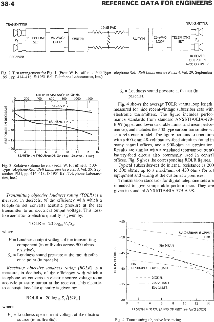
Transmitting objective loudness rating
(TOLR)
is a
measure, in decibels, of the efficiency with which a
telephone set converts acoustic pressure at the set
transmitter to an electrical output voltage. This loss-
like acoustic-to-electric quantity is given by:
TOLR
=
-20 loglo
V,/S,
where
V,
=
Loudness output voltage of the transmitting
component
(in
millivolts across 900 ohms
resistive),
ence point (in pascals).
S,
=
Loudness sound pressure
at
the mouth refer-
Receiving objective loudness rating
(ROLR)
is a
measure, in decibels, of the efficiency with which a
telephone set converts an electric source voltage to an
acoustic pressure output at the receiver. This electric-
to-acoustic loss-like quantity is given by:
ROLR
=
-20
log,,
Se/()iV,v)
where
V,v
=
Loudness open-circuit voltage
of
the electric
source (in millivolts),
S,
=
Loudness sound pressure at the ear (in
pascals).
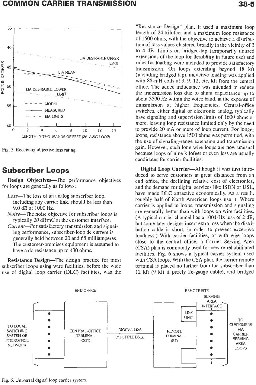
Fig. 4 shows the average TOLR versus loop length,
measured for nine recent-vintage subscriber sets with
electronic transmitters. The figure includes perfor-
mance standards from standard ANSI/TIA/EIA-470-
B-97 (upper and lower desirable
limits,
and mean perfor-
mance), and includes the 500-type carbon-transmitter set
as a reference model. The figure pertains
to
operation
with a 400-ohm 48-volt battery-feed circuit
as
found in
many central offices, and a 900-ohm ac termination.
Results are similar with a regulated (constant-current)
battery-feed circuit also commonly used in central
offices. Fig.
5
gives the corresponding ROLR figures.
Typical subscriber-set dc internal resistance is 200
to
300
ohms,
up
to
a maximum of
430
ohms
for all
equipment and wiring at the customer’s premises.
Transmission standards for digital telephone sets are
intended
to
give comparable performance. They are
given in standard ANSI/TIA/EIA-579-A-98.
-55
1
-
50
3
-45
j
z
5
-40
P
MODEL
MEASURED
-351
EIA
LIMITS
-
30
0
2
4
6
8101214
LENGTH IN THOUSANDS
OF
FEET (26-AWG LOOP)
Fig.
4.
Transmitting objective
loss
rating.
38-5
35
I
Y
3
45
2
6
5
50
0
n:
55
EIA DESIRABLE UPPER
LIMIT
EIA MEAN
-
EIA DESIRABLE LOWER
LIMIT
MODEL
MEASURED
EIA LIMITS
____
-
60
0
2
4
6
8101214
LENGTH
IN
THOUSANDS OF FEET (26-AWG LOOP)
Fig.
5.
Receiving objective
loss
rating.
Subscriber
Loops
Design Objectives-The performance objectives
Loss-The loss of
an
analog subscriber loop,
for loops are generally as follows:
including any carrier link, should be less than
9.0
dB at
1000
Hz.
Noise-The noise objective for subscriber loops is
typically 20 dBmC at the customer interface.
Current-For satisfactory transmission and signal-
ing performance, subscriber-loop dc current is
generally held between 20 and 65 milliamperes.
The customer-premises equipment is assumed to
have a dc resistance up to
430
ohms.
Resistance Design-The design practice for most
subscriber loops using wire facilities, before the wide
use of digital loop carrier (DLC) facilities, was the
TO
LOCAL
SWITCHING
SYSTEM
OR
INTEROFFICE
NETWORK
“Resistance Design” plan. It used a maximum loop
length of
24
kilofeet and a maximum loop resistance
of
1500
ohms, with the objective to achieve a distribu-
tion of loss values clustered broadly in the vicinity of
3
to
4
dB. Limits
on
bridged-tap (temporarily unused
extensions of the loop for flexibility in future use) and
rules for loading were included
to
provide satisfactory
transmission. On loops extending beyond
18
kft
(including bridged tap), inductive loading was applied
with 88-mH coils at
3,
9,
12, etc. kft from the central
office. The added inductance was intended to reduce
the transmission loss due to shunt capacitance up to
about
3500
Hz
within the voice band, at the expense of
transmission at higher frequencies. Central-office
switches, either digital or electronic analog, typically
have signaling and supervision limits of
1600
ohms or
more, leaving loop resistance limited only by the need
to provide 20 mA or more
of
loop current. For longer
loops, resistance above
1500
ohms
was permitted, with
the use of signaling-range extension and transmission
gain. However, such long wire loops are now unusual
because loops of nine kilofeet or even less
are
usually
candidates for carrier facilities.
Digital
Loop
Carrier-Although it was first intro-
duced to serve customers at great distances from
an
end office, the declining relative cost
of
electronics,
and the demand for digital services like
ISDN
or DSL,
have made DLC attractive economically. As a result,
roughly half of North American loops use it. Where
carrier is applied
to
loops, transmission and signaling
are
generally better than with loops
on
wire facilities.
(A typical carrier channel has a
1004-Hz
loss
of
2 dB,
but some later designs insert extra loss when the distri-
bution cable is short, in order
to
prevent excessive
loudness.) With carrier facilities, or with wire loops
close to the central office, a Carrier Serving Area
(CSA) plan is commonly used for new or rehabilitated
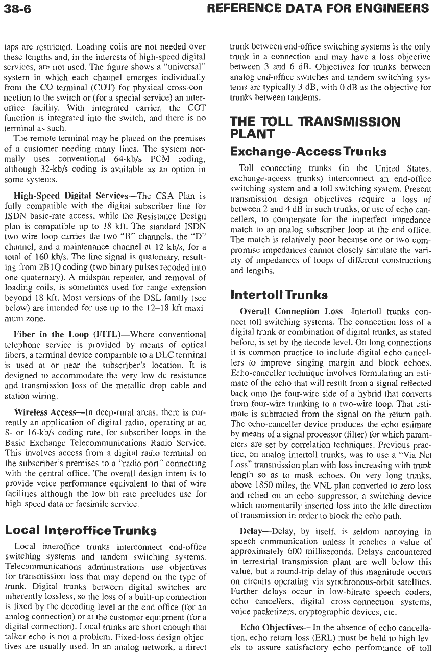
facilities. Fig. 6 shows a typical carrier system used
with CSA loops. With the CSA plan, the carrier remote
terminal is placed
no
farther from the subscriber than
12
kft
(9
kft if purely 26-gauge cable), and bridged
END OFFICE
r
CENTRAL-OFFICE
TERMINAL
(COT)
(MULTIPLE DSls)
REMOTE SITE
SERVING
AREA
INTERFACE>
REMOTE
TERMINAL
IRT)
TO
CUSTOMERS
VIA
CARRIER
SERVING
AREA
LOOPS
Fig.
6.
Universal digital
loop
carrier
system
taps are restricted. Loading coils are not needed over
these lengths and, in the interests of high-speed digital
services, are not used. The figure shows a “universal”
system in which each channel emerges individually
from the CO terminal (COT) for physical cross-con-
nection to the switch or (for a special service) an inter-
office facility. With integrated carrier, the COT
function
is
integrated into the switch, and there is
no
terminal as such.
The remote terminal may be placed
on
the premises
of a customer needing many lines. The system nor-
mally
uses
conventional 64-kb/s PCM coding,
although 32-kb/s coding is available as an option in
some systems.
High-speed Digital Services-The CSA Plan is
fully compatible with the digital subscriber line for
ISDN
basic-rate access, while the Resistance Design
plan is compatible up to 18 kft. The standard
ISDN
two-wire loop carries the two “B” channels, the “D”
channel, and a maintenance channel at 12 kb/s, for a
total
of
160 kb/s. The line signal is quaternary, result-
ing from 2BlQ coding (two binary pulses recoded into
one quaternary).
A midspan repeater, and removal of
loading coils, is sometimes used for range extension
beyond 18
kft.
Most versions of the DSL family (see
below) are intended for use up to the 12-18
kft
maxi-
mum zone.
Fiber
in
the
Loop
(F1TL)-Where conventional
telephone service is provided by means of optical
fibers, a terminal device comparable
to
a
DLC terminal
is
used at or near the subscriber’s location. It is
designed
to accommodate the very low dc resistance
and transmission loss of the metallic drop cable and
station wiring.
Wireless Access-In deep-rural areas, there is cur-
rently an application of digital radio, operating at an
8-
or 16-kb/s coding rate, for subscriber loops in the
Basic Exchange Telecommunications Radio Service.
This involves access from a digital radio terminal
on
the subscriber’s premises
to
a “radio port” connecting
with the central office. The overall design intent is to
provide voice performance equivalent to that of wire
facilities although the low bit rate precludes use for
high-speed data or facsimile service.
Local Interoffice Trun
ks
Local interoffice trunks interconnect end-office
switching systems and tandem switching systems.
Telecommunications administrations use objectives
for transmission
loss
that may depend
on
the type of
trunk. Digital trunks between digital switches are
inherently lossless,
so
the loss of a built-up connection
is fixed by the decoding level at the end office (for an
analog connection) or at the customer equipment (for
a
digital connection). Local trunks are short enough that
talker echo is not a problem. Fixed-loss design objec-
tives are usually used.
In
an analog network, a direct
trunk between end-office switching systems is the only
trunk in a connection and may have a loss objective
between 3 and
6
dB. Objectives for
trunks
between
analog end-office switches and tandem switching sys-
tems are typically
3
dB, with
0
dB as the objective for
trunks between tandems.
THE
mLL
TRANSMISSION
PLANT
Exchange-AccessTrunks
Toll connecting
trunks
(in the United States,
exchange-access
trunks)
interconnect an end-office
switching system and a toll switching system. Present
transmission design objectives require a loss of
between
2
and
4
dB in such trunks, or use of echo can-
cellers, to compensate for the imperfect impedance
match to an analog subscriber loop at the end office.
The match is relatively poor because one or two com-
promise impedances cannot closely simulate the vari-
ety of impedances of loops of different constructions
and lengths.
lntertoll Trun ks
Overall Connection Loss-Intertoll trunks con-
nect toll switching systems. The connection
loss
of a
digital trunk or combination of digital trunks, as stated
before, is set by the decode level. On long connections
it is common practice to include digital echo cancel-
lers to improve singing margin and block echoes.
Echo-canceller technique involves formulating
an
esti-
mate of the echo that will result from
a
signal reflected
back onto the four-wire side of a hybrid that converts
from four-wire trunking to
a
two-wire loop. That esti-
mate is subtracted from the signal
on
the return path.
The echo-canceller device produces the echo estimate
by means of a signal processor (filter) for which param-
eters are set by correlation techques. Previous prac-
tice,
on
analog intertoll trunks, was to use a “Via Net
Loss” transmission plan with loss increasing with
trunk
length so
as
to
mask echoes.
On
very long
trunks,
above
1850
miles, the
VNL
plan converted to zero loss
and relied
on
an echo suppressor, a switching device
which momentarily inserted loss into the idle direction
of transmission in order to block the echo path.
Delay-Delay, by itself, is seldom annoying in
speech communication unless it reaches a value of
approximately
600
milliseconds. Delays encountered
in terrestrial transmission plant are well below this
value, but a round-trip delay of this magnitude occurs
on circuits operating via synchronous-orbit satellites.
Further delays occur in low-bitrate speech coders,
echo cancellers, digital cross-connection systems,
voice packetizers, cryptographic devices, etc.
Echo Objectives-In the absence of echo cancella-
tion, echo return loss (ERL) must be held to high lev-
els to assure satisfactory echo performance
of
toll
COMMON CARRIER TRANSMISSION
38-7
facilities. The ERL objective for analog loops at the
end office is typically
11
dB. With the general use of
four-wire switching, this is the only relevant echo
source in a built-up connection. (Historically, in the
important special case
of
a two-wire interface
to
a toll
connecting trunk at an analog toll office, the ERL was
held
to
a minimum 16 dB, with an objective of 22
dF3.)
DIGITAL
SUBSCRIBER
LINE
An emerging application of network elements hav-
ing great near-term importance is the Digital Sub-
scriber Line. This facility does not necessarily provide
switched service in the usual sense-its most visible
application is for “always-on” access to an
ISP.
In that
sense, it is a private-line channel from one user to a
DSL access multiplexer (DSLAM). The DSLAM
aggregates the data traffic from a group
of
users,
usu-
ally by packet switching via Asynchronous Transfer
Mode (ATM) techniques in the interoffice environ-
ment. (See Chapter 26.)
This is an emerging technology whose standards are
still evolving, with a variety of pre-standard and pro-
prietary versions being made available. Some imple-
mentations of them use equipment built into the line
card of a digital switch or DLC terminal to minimize
the effort of installation. The core idea
is
to send bi-
directional digital data, usually on a two-wire loop, at
previously unattainable speeds by use of combinations
of signal processing, automatic equalization, error cor-
rection, and echo cancellation. The base facility is the
nonloaded copper subscriber loop. The terminals com-
pensate for signal attenuation at high frequencies,
irregularities in transmission and echoes caused by
bridged taps and changes
in
gauge at splices, crosstalk
from the other direction of transmission and other DSL
systems in the same cable, errors caused by impulse
noise, and even radio-frequency interference from
broadcast stations.
On a given loop, the speed attainable may be con-
trolled by either the technical conditions of the loop or
by marketing considerations of the service provider.
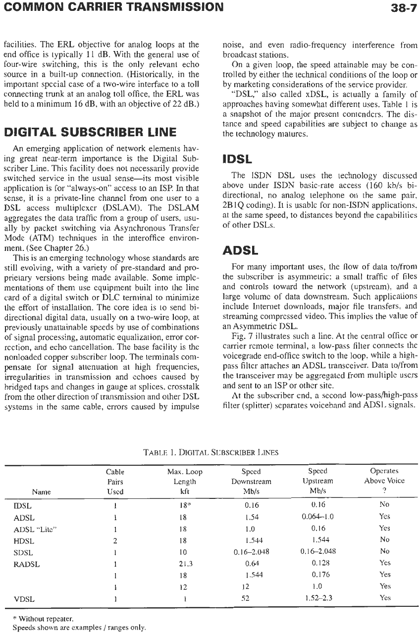
“DSL,” also called xDSL, is actually a family of
approaches having somewhat different uses. Table
1
is
a snapshot of the major present contenders. The dis-
tance and speed capabilities are subject to change
as
the technology matures.
The ISDN DSL uses the technology discussed
above under ISDN basic-rate access
(160
kb/s bi-
directional, no analog telephone on the same pair,
2B1Q coding). It is usable for non-ISDN applications,
at the same speed,
to
distances beyond the capabilities
of other DSLs.
For many important uses, the flow of data to/from
the subscriber is asymmetric: a small traffic
of
files
and controls toward the network (upstream), and a
large volume of data downstream. Such applications
include Internet downloads, major file transfers, and
streaming compressed video. This implies the value of
an
Asymmetric DSL.
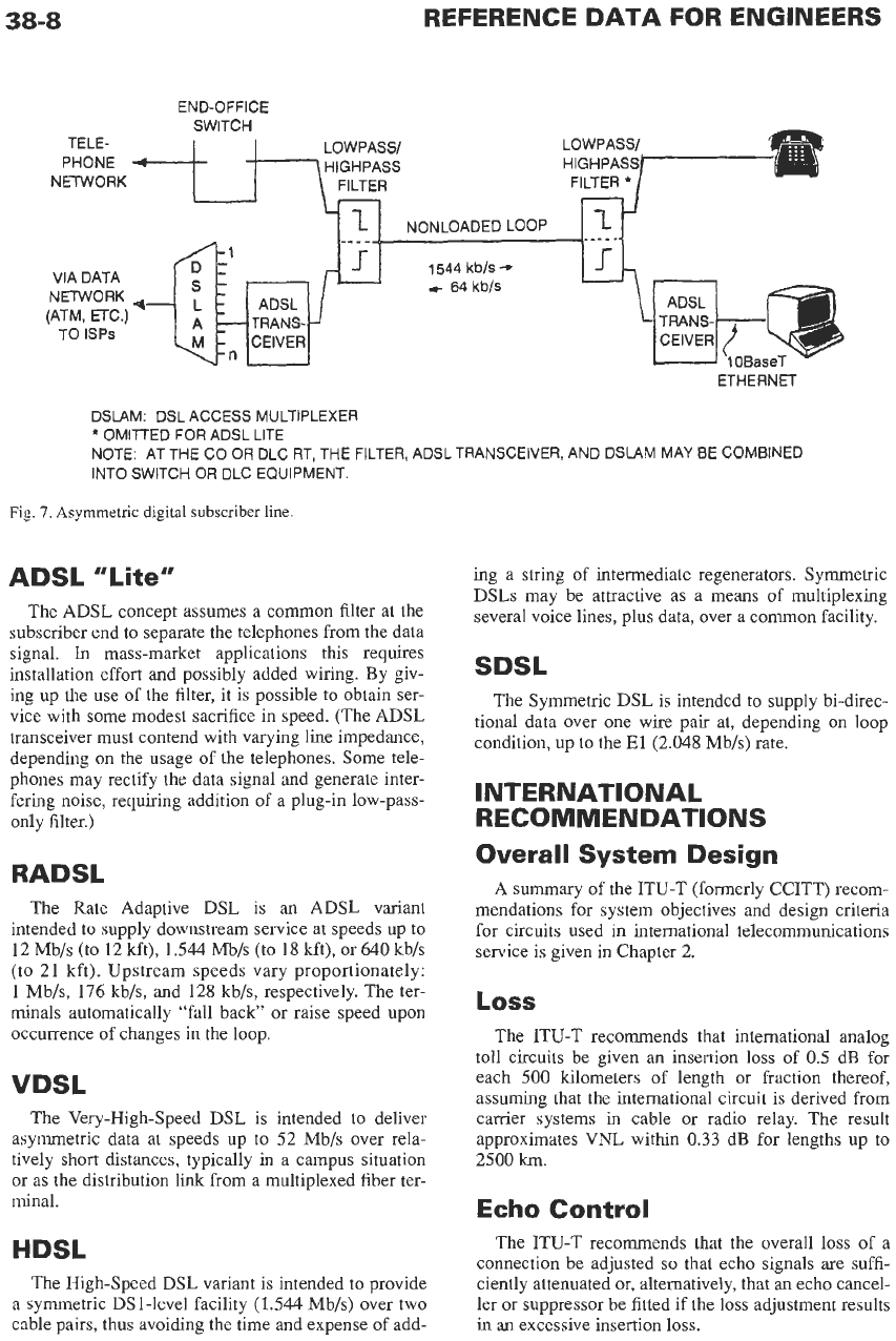
Fig.
7
illustrates such a line. At the central office or
carrier remote terminal, a low-pass filter connects the
voicegrade end-office switch to the loop, while a high-
pass filter attaches an ADSL transceiver. Data to/from
the transceiver may be aggregated from multiple users
and sent to an
ISP
or other site.
At the subscriber end, a second low-passhigh-pass
filter (splitter) separates voiceband and ADSL signals.
TABLE 1. DIGITAL
SUBSCRIBER
LAW
Cable
Max.
Loop Speed Speed Operates
Pairs Length
Downstream Upstream Above Voice
Name
Used
kft
Mb/s
Mb/s
?
IDSL
1
18*
0.16 0.16
No
ADSL
1
18
1.54
0.064-1
.O
Yes
ADSL ‘‘Lite”
1
18
1
.o
0.16
Yes
HDSL
2
18
1.544
1.544
No
SDSL
1
10
0.16-2.048
0.16-2.048
No
RADSL
1
21.3
0.64
0.128
Yes
1
18
1.544
0.176
Yes
1
12
12
1.0
Yes
VDSL
1
1
52
1.52-2.3
Yes
*
Without repeater.
Speeds
shown
are examples
/
ranges only.
38-8
REFERENCE
DATA
FOR
ENGINEERS
END-OFFICE
SWITCH
LOWPASSl
HIGHPASS
NETWORK
FILTER
VIA DATA
NETWORK
(ATM,
ETC.)
TO lSPs
NONLOADED LOOP
CEIVER CEIVER
ETHERNET
DSLAM: DSL ACCESS MULTIPLEXER
*
OMITTED
FOR
ADSL LITE
NOTE: AT THE CO
OR
DLC RT, THE FILTER,
ADSL
TRANSCEIVER, AND DSLAM MAY BE COMBINED
INTO SWITCH
OR
DLC EQUIPMENT,
Fig.
7.
Asymmetric
digital
subscriber
line
ADS
L
”
Lit e
”
The ADSL concept assumes a common filter at the
subscriber end to separate the telephones from the data
signal.
In
mass-market applications this requires
installation effort and possibly added wiring. By giv-
ing up the use of the filter, it is possible to obtain ser-
vice with some modest sacrifice in speed. (The ADSL
transceiver must contend with varying line impedance,
depending on the usage of the telephones. Some tele-
phones may rectify the data signal and generate inter-
fering noise, requiring addition of a plug-in low-pass-
only filter.)
RADSL
The Rate Adaptive DSL is an ADSL variant
intended to supply downstream service at speeds up to
12 Mb/s (to 12 kft),
1.544
Mb/s
(to
18
kft), or 640
kb/s
(to 2
1
kft). Upstream speeds vary proportionately:
1
Mb/s,
176
kb/s, and 128 kb/s, respectively. The ter-
minals automatically “fall back’ or raise speed upon
occurrence of changes in the loop.
VDSL
The Very-High-speed DSL is intended to deliver
asymmetric data at speeds up to 52 Mb/s over rela-
tively short distances, typically in a campus situation
or
as the distribution link from a multiplexed fiber ter-
minal.
HDSL
The High-speed DSL variant is intended to provide
a symmetric
DS
1
-level facility (1.544 Mb/s) over two
cable pairs, thus avoiding the time and expense of add-
ing a string of intermediate regenerators. Symmetric
DSLs may be attractive as a means of multiplexing
several voice lines, plus data, over a common facility.
SDSL
The Symmetric DSL is intended to supply bi-direc-
tional data over one wire pair at, depending on loop
condition, up to the
El
(2.048
Mb/s)
rate.
INTERNATIONAL
RECOMMENDATIONS
Overall System Design
A summary of the ITU-T (formerly
CCITT)
recom-
mendations for system objectives and design criteria
for circuits used
in
international telecommunications
service is given in Chapter 2.
Loss
The ITU-T recommends that international analog
toll circuits be given an insertion loss of
0.5
dB
for
each
500
kilometers of length or fraction thereof,
assuming that the international circuit
is
derived from
carrier systems
in
cable or radio relay. The result
approximates
VNL
within
0.33
dB for lengths up to
2500
km.
Echo
Control
The ITU-T recommends that the overall loss of a
connection be adjusted
so
that echo signals are suffi-
ciently attenuated or, alternatively, that
an
echo cancel-
ler or suppressor be fitted if the loss adjustment results
in an excessive insertion loss.
COMMON CARRIER TRANSMISSION
38-9
QUALITY OBJECTIVES AND
DEFINITIONS
Noise
Noise-Noise, in its broadest definition, is any
undesired signal in a communication channel. Noise
may be classified as quantizing, or signal-dependent,
noise; thermal, or white, noise; impulse noise;
crosstalk tone interference; and miscellaneous.
When noise is measured on a voiceband communi-
cation channel, a weighting network is often inserted
ahead of the detector to account for the varying subjec-
tive annoyance from noise of different frequencies into
telephone sets, or differing interference into a data
modem
(Modulator-DEModulator).
For noise mea-
surement on channels of bandwidth greater than voice,
weighting networks with correspondingly greater
bandwidths are used.
Quantizing Noise-Noise occurring in the pres-
ence of signal, resulting from a mismatch between the
exact value of an analog signal and the closest avail-
able quantizing step in a digital coder.
Thermal Noise-Noise arising from random elec-
tron motion, occurring on all transmission media and
in all communications apparatus. It is characterized by
uniform energy distribution over the frequency spec-
trum and by a normal or Gaussian distribution of volt-
age or current.
Impulse Noise-Noise consisting of irregular
pulses of short duration and relatively high amplitude.
Some sources of impulse noise induced in communi-
cation channels are an erroneous digital coding bit
caused by an error on a transmission facility, crosstalk
from dc signaling systems, lightning, or transients due
to switching in adjacent power circuits.
Tone Interference-Interference due to single
tones or complex periodic waveforms.
readily be placed in any of the preceding categories.
Miscellaneous Noise-Interferences that cannot
Reference Noise-One picowatt (lo-’’ watt) of
power. Also commonly stated as
-90
dBm (90 dB
below one milliwatt).
dBrn-Decibels above reference noise. The dBm is
the unit of measurement
of
noise power used in the
IEEE Standard 743-1995 noise-measuring set. For
measuring noise on voice communication channels,
the noise-measuring set is normally equipped with a
“C-message” weighting network. When
this
filter is
used, the unique network response causes
the
reading to
deviate from what would be obtained with some other
network. Readings in dBm taken with the C-message
network are designated “dBmC.” The calibration tone
is
0
dBm (1 mW) at 1000 Hz, which reads
90
dbrn
with or without the C-message weighting network.
One milliwatt of white noise, limited
to
the band of
0-
3 kHz, reads
88
dBrn.
The noise objective
in
present use is that, on any
digital connection, the noise should not exceed 17
dBmC, as controlled mainly by the decoder at the
receiving end.
pWp-Picowatts, psophometrically weighted. The
unit of noise power measured with the ITU-T-recom-
mended psophometer (“noise meter”). The meter is
frequency-weighted by a curve comparable to the
C-message weighting curve. The reference tone is
-90
dBm (1 picowatt) at
800
Hz. The psophometer is
defined as measuring the internal (open-circuit) volt-
age of an equivalent noise generator having impedance
of 600 ohms and delivering noise power
to
a 600-ohm
load. For convenience in comparison,
the
psophomet-
ric voltage may be converted to dBm.
In
such a case, a
tone of
0
dBm at 1000 Hz will read
+1
dBm on the
psophometer; one mW of white noise, limited to the
0-3 kHz band, reads -2 dBm.
Levels
and
Loss
Reference Level Point-An analog point in a com-
munication circuit arbitrarily chosen as a reference
location for signal-level measurements. Common
equivalent terms are
“0
dB transmission level point,”
“zero level,” “zero level point,”
“0
dB TL,”
“0
dB
TLP,” and
“0
TLP.”
Relative Level-The relative level at any point in a
circuit
is
the power gain or loss in decibels between
the
0
TLP and the point under consideration. Refer-
ence of signal and interference powers to the
0
TLP is
convenient in system design and maintenance. Rela-
tive level is expressed
in
such terms as “-3 dB TLP.”
Common practice is to define the input of a digital
coder in a switch or transmission system as the
0
TLP.
At the distant end, the corresponding decoder is con-
ventionally at a TLP of -3 dB,
4
dB,
etc. Signal and/or
interference powers may be referred to the
0
TLP with
a phrase such as “a signal power of -16 dBmO,” which
indicates the power of the signal
if
it were measured at
the
0
TLP. The
0
TLP may not be accessible for mea-
surement and, in fact, need not even exist in a given
system.
Net Loss-The net loss of a transmission channel is
the ratio of the signal powers at the input and the out-
put
of
the
channel,
usually
expressed
in
decibels (dB).
By custom, the net loss of a channel is understood to be
measured at
1004
hertz in the American and Canadian
plant and at 1020 (formerly
800)
hertz in international
practice (ITL-T). (The measurement frequency is
dis-
placed slightly from
1000
Hz to keep it from being a
subharmonic of
8000
Hz,
the sampling rate in a digital
coder, to avoid generation of distortion products.)
Insertion Loss-The ratio of the power delivered
from a source to a load, to the power delivered from