Middleton W.M. (ed.) Reference Data for Engineers: Radio, Electronics, Computer and Communications
Подождите немного. Документ загружается.

36-2
REFERENCE
DATA
FOR ENGINEERS
Coverage
36-13
Doppler Frequency Shift
36-14
Pulse Radars That Employ Doppler
36-14
MTI Radar
36-1 6
MTI Performance Limitations
Pulse Compression
36-1
8
Clutter
36-1
8
Radar Measurement Accuracy
36-21
RMS Range Measurement Error
RMS Doppler Frequency Measurement Error
RMS Angle Measurement Error
Tracking with Radar
36-21
RADAR
36-3
INTRODUCTIONTO RADAR
Radar is an electromagnetic sensor that greatly
extends one’s ability to detect reflecting objects (or tar-
gets) at long or short range and to accurately locate tar-
gets in fair, as well as poor weather. Since its
introduction during the second world war, radar has
been a vital part of air defense in its many forms and
for other military missions such as battlefield surveil-
lance, fighter/attack aircraft, ballistic missile defense,
and antisubmarine warfare.
It
has also been important
for many nonmilitary applications including weather
observation (precipitation, severe storms, winds, and
wind shear), observing beneath the ever-present clouds
of a planet like Venus, probing below the surface of the
Earth, high-resolution imaging of the Earth’s surface
in three dimensions, and for mapping of sea ice for the
more efficient routing of shipping in northern regions.
Targets of interest to radar have been aircraft, ships,
missiles, spacecraft, vehicles, people, birds, insects, as
well as the natural environment.
Radar operates by radiating from
an
antenna, a
known waveform, usually a series of short-duration
pulses. After a portion of the radiated energy is
reflected by a target and returned
to
the radar, it is
received by the antenna and processed in the receiver
to detect the presence of a target and to determine
something about its nature. Two of the basic measure-
ments made by a radar
are
range
(distance) and
angu-
lar location
of a target. By observing the location of a
target over time, the radar can establish its trajectory,
or
track,
and predict the target’s future location. Many
modern radars use to advantage the shift in frequency
(relative to the frequency that was transmitted) of the
echo signal from a moving target. The shift of the echo
signal frequency from a moving target is caused by the
doppler effect, something familiar from high school or
college physics. The doppler frequency shift is propor-
tional to the
radial velocity
of the target, so it can be
used to separate the frequency-shifted signals from
moving targets (such
as
aircraft) from large undesired
stationary
clutter
echo signals from the land, sea, and
weather.
It
is an important part of
MTI
(moving target
indication), pulse doppler, and
CW (continuous wave)
radars that have to detect small moving targets in the
midst of very large clutter echoes. The doppler shift is
also the basis for meteorological radars that detect and
recognize hazardous weather effects to provide infor-
mation about the environment not readily available by
other means. In addition to the usual measurements of
range, angular location, relative velocity, and target
track, radar sometimes can obtain information about
the size, shape, symmetry, and surface properties of a
target.
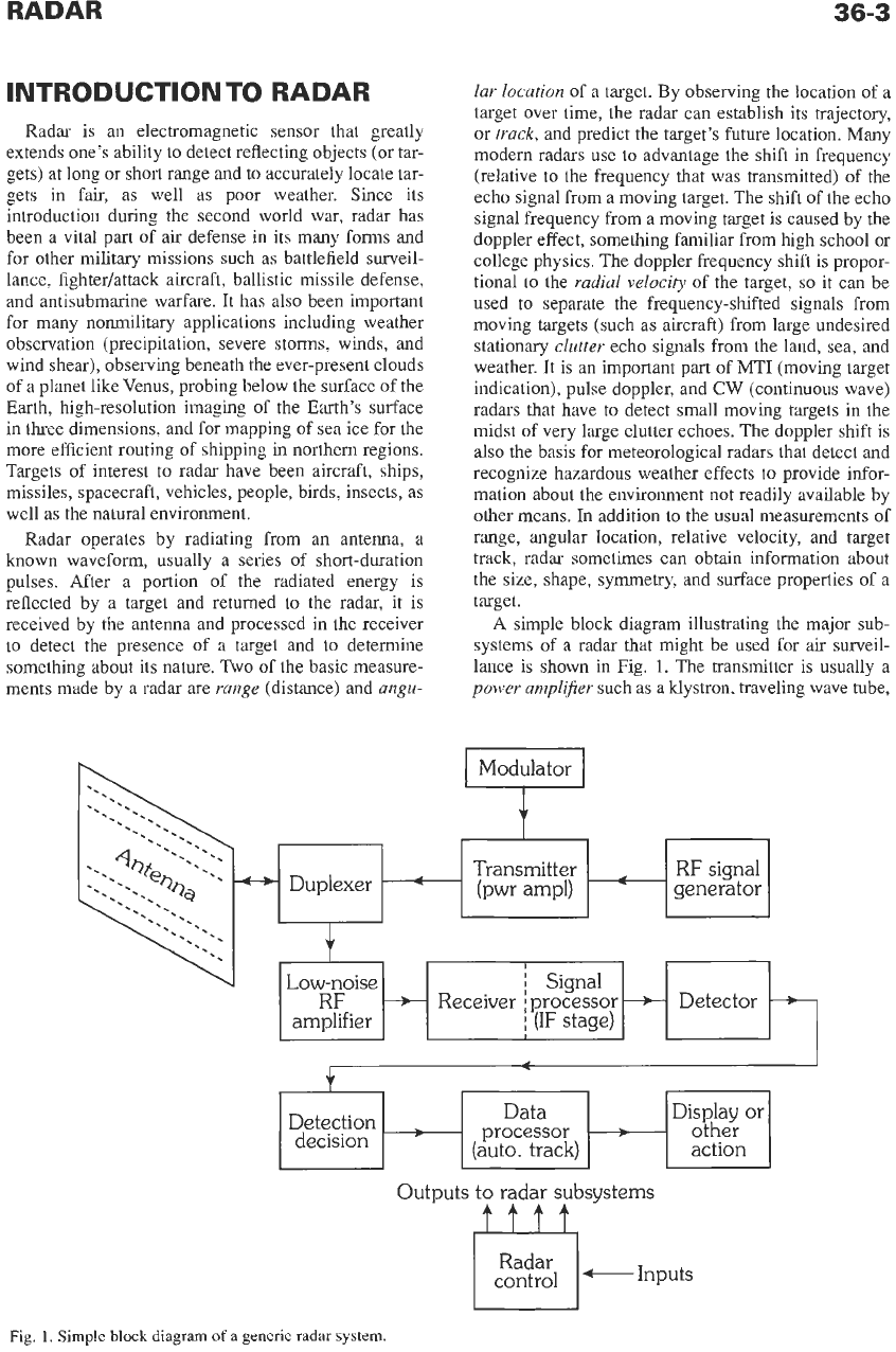
A simple block diagram illustrating the major sub-
systems of a radar that might be used for
air
surveil-
lance is shown in Fig.
1.
The transmitter is usually a
power amplifier
such as a klystron, traveling wave tube,
t
Display
or
Detection processor other
decision (auto. track) action
Outputs
to
radar subsystems
I
I
Fig.
1.
Simple block diagram
of
a generic radar system.
or transistor. Although the magnetron oscillator was
widely used in the early days of radar, its limited aver-
age-power, poor stability, and inability to generate
sophisticated modulated waveforms restrict its applica-
tion to radars with only modest capability. The first
stage of the receiver is often a
low-noise transistor
amplger.
In
a superheterodyne receiver, the echo is
converted by a
mixer
and
local oscillator
(not shown)
to an intermediate frequency
(IF),
where the signal is
amplified and subject to signal processing to extract the
desired signal and reject or attenuate undesired signals
and noise.
An
important example of a
signal processor
is
the
matched filter
that maximizes the ratio
of
the
peak-signal-to-mean-noise output
of
the receiver,
which in turn maximizes the detectability of the desired
signal.
In
a receiver with a matched filter, the peak-out-
put-signal-to-mean-noise-power ratio is
=/No,
where
E
=
signal energy and
No
=
noise power per unit band-
width. Thus detectability of a radar signal when a
matched filter is used does not depend on the shape
of
the signal or its bandwidth, but only on
its
total energy.
The
detector
stage following the
IF
stage extracts the
signal modulation from the carrier frequency.
In
a radar
where there are
no
undesired clutter echoes to compete
with the detection of the desired target echoes, the
detector stage is an
envelope detector
(also called the
second detector).
In
a radar that employs the doppler
frequency
shift
to separate (by the use of filters) desired
moving targets from undesired fixed clutter echoes, the
detector stage is a
phase detector.
It requires a refer-
ence signal (not shown) that is a faithful representation
of the transmitted signal
so
as to recognize that the
echo signal has experienced a doppler shift. A
video
ampl@er
(not shown) following the detector amplifies
the signal and a decision is made whether the receiver
output is due to a target (signal plus noise) or is due to
noise alone. The
detection decision
is based on observ-
ing when the receiver output exceeds a predetermined
threshold whose level depends on achieving an accept-
able probability
of
false alarm.
In
early radars the
detection decision was made by an operator viewing a
radar display, but
in
modem radars the decision
whether
or
not a target has been detected is made auto-
matically without direct operator intervention.
The received signal
is
digitized for processing,
either after the detector stage
(in
the video) or before
the detector (in the
IF),
especially in radars that
depend
on
the doppler frequency shift for detection
of
moving targets. Digital processing makes it possible to
automatically detect and accurately track many hun-
dreds or thousands of targets
so
as to present fully pro-
cessed tracks rather than individual detections or
“raw” (unprocessed) radar data. The automatic tracker
is an example of a
data processor.
The processed out-
put of the radar or the established tracks of targets
might be displayed to an operator or used to perform
some automated operation. The
antenna
can be one of
several different forms of mechanically steered para-
bolic reflectors, a mechanically steered planar array, or
one
of
several types
of
electronically steered phased
arrays. The
duplexer
is the device that allows a single
antenna to be time-shared between the transmitter and
the receiver.
A typical long-range air-surveillance radar might
have a resolution in the range dimension of about one
or
two hundred meters. When required, a radar can
have a range resolution of a small fraction of a meter.
The beamwidth of a radar antenna might typically be
one or two degrees, but some operational radars have
had beamwidths as small as
0.3
degree. Thus the reso-
lution in the cross-range dimension (determined by the
beamwidth and the target range) is usually much
worse than the range resolution.
It
is possible, how-
ever, to achieve high resolution
in
the cross-range
dimension comparable to the resolution achieved in
the range dimension by employing synthetic aperture
radar
(SAR).
Here the resolution of a large antenna is
obtained by utilizing a small antenna on a moving plat-
form, such as an aircraft, to store the received echoes
over a relatively long time
so
as to synthesize (virtu-
ally) in a digital processor the equivalent of a large
antenna. The output of a
SAR
is usually a high resolu-
tion map or image of a target scene.
Radar is generally found within what is known as
the microwave region of the electromagnetic spectrum
from about
400
MHz to
40
GHz; but there have been
many operational radars in the
VHF
region
(30
to
300
MHz) as well as
in
the HF region
(3
to
30
MHz).
An
HF over-the-horizon radar can reach out to ranges of
about
2000
nmi by utilizing refraction from the iono-
sphere. Radar has also been considered for use at fre-
quencies higher than the microwave region, at
millimeter wavelengths. Laser radars are found in the
IR
and optical regions of the spectrum, where they can
provide precision range and radial-velocity measure-
ment.
PREDICTION
OF
RADAR
RANGE*
The radar range equation is important not only for
predicting the range performance of a radar, but to act
as a focus for radar design and for better understanding
the factors that affect radar performance. The simple
form
of
the radar range equation is
where
P,.
=
received echo signal power in watts,
P,
=
transmitted signal power in watts,
G
=
antenna gain,
A,
=
antenna effective area in square meters,
m
=
radar cross section of the target in square
R
=
range
to
the target in meters.
meters,
*
Reference
1.
RADAR
36-5
If a single antenna is used for both transmitting and
receiving, as is usually the case,
G
=
47rAJA
’,
where
A
is the radar wavelength in meters. Then
P,
=
PtG2A2u/[(4~)3R4]
(Eq. lb)
=
P,Azu/[47rA2R4]
The maximum range
R,,
of a radar occurs when
the received signal
P,
=
Smin,
the minimum detectable
signal. The minimum detectable signal is a statistical
quantity limited by receiver noise. It can be written as
where
k
=
Boltzmann’s constant,
To
=
standard temperature (290
K),
B
=
receiver bandwidth in hertz,
F,
=
receiver noise figure,
for reliable detection.
kT,
=
4
x
W/Hz
(S/N),
=
minimum signal-to-noise ratio required
The received echo signal power can be increased
by integrating (adding) a number of echo signal
pulses
n.
This can be incorporated into the radar
equation by dividing
Smin
by
nE,(n),
where
Ei(n)
is the
efficiency with which the
n
pulses can be integrated.
Since the average power
P,
is more indicative of
radar capability than
is
the peak power, it is intro-
duced via the relation
where
r
=
pulse width in seconds,
fp
=
pulse repetition frequency in hertz.
With the above, the form of the radar equation suitable
for calculating the range
is
The radar system losses
L,
(number greater than
one) have been included. For most radars designed
with
a
matched filter receiver (a filter that maximizes
the output signal-to-noise ratio), the product
BT
=
1.
[In Eq.
4,
(S/N)l/nEi(n)
is the required signal-to-noise
ratio per pulse
(SIN),.]
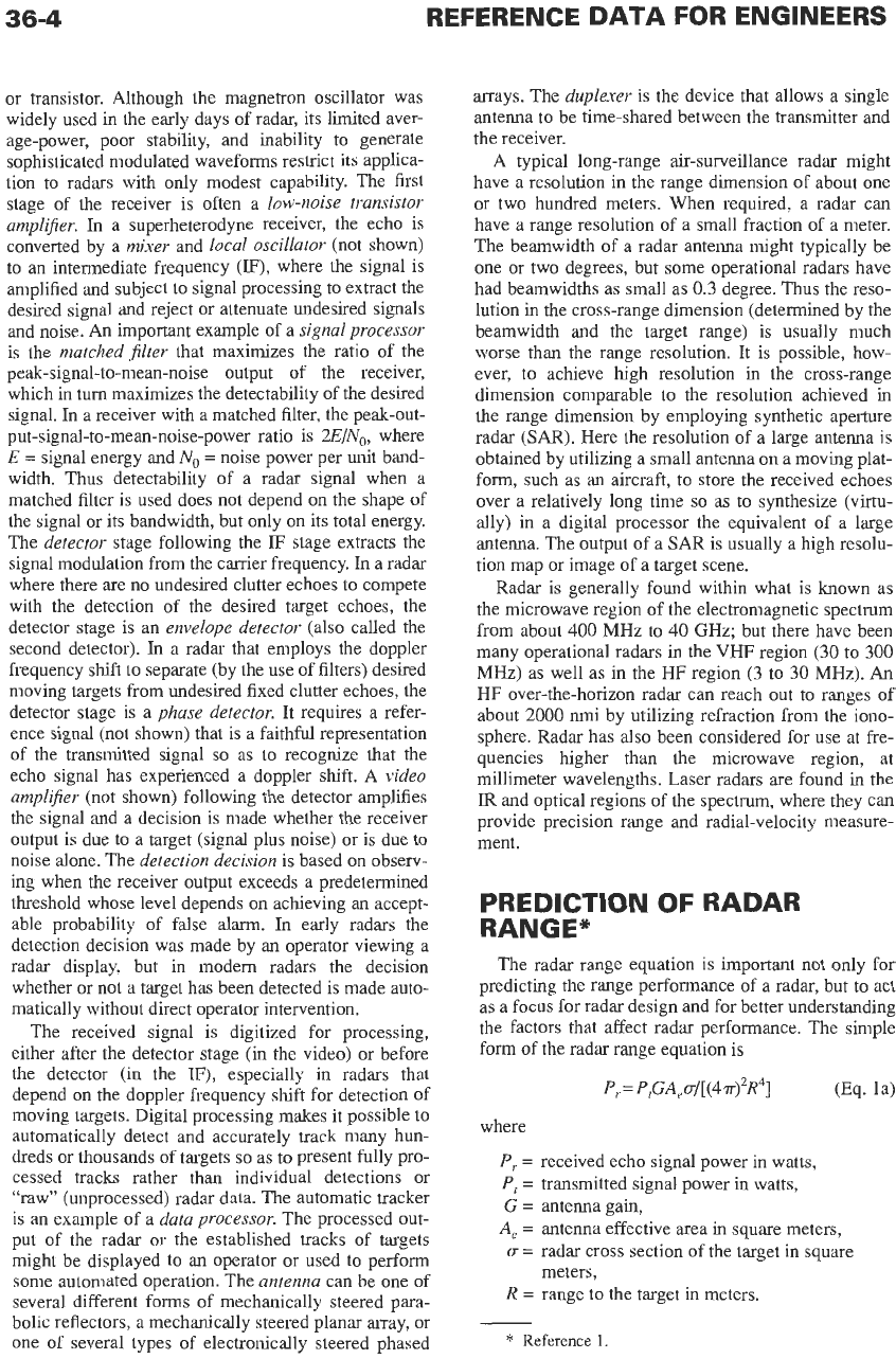
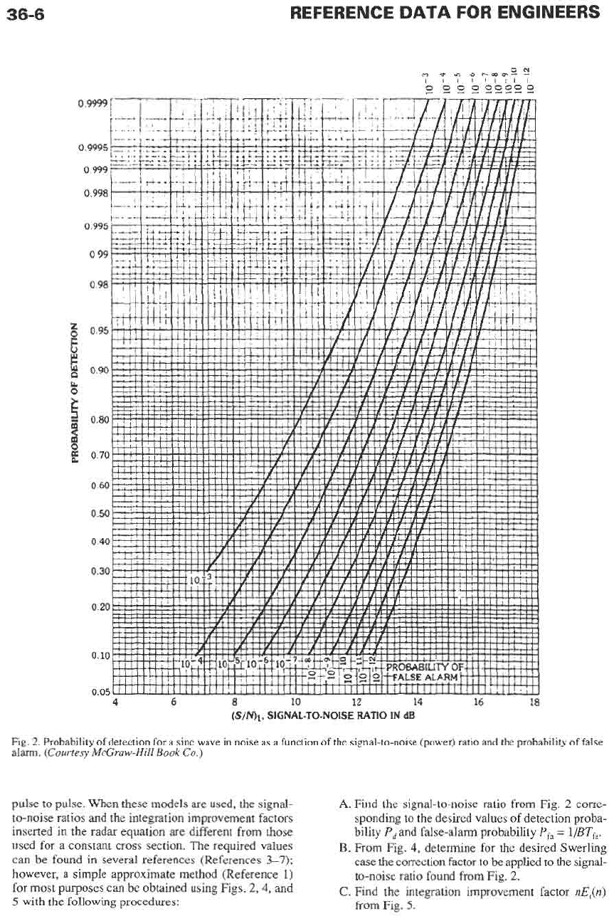
Fig. 2 shows the relationship of the required signal-
to-noise ratio
(SiN),
to the probability
of
detection and
the probability of false alarm. The probability of detec-
tion is usually taken
as
0.90, but sometimes it is quoted
as
0.5
or
0.8.
Its choice is
usually
the prerogative of the
customer. The probability of
a
false alarm
is
given here
as
where
B
=
receiver bandwidth in hertz,
Tfa
=
average time between false alarms.
The reciprocal of
P,
is
ns.
the false-alm number.
The false-alarm time
Tfa
is usually specified for radar
performance rather than the probability of false alarm
or the false-alarm number.
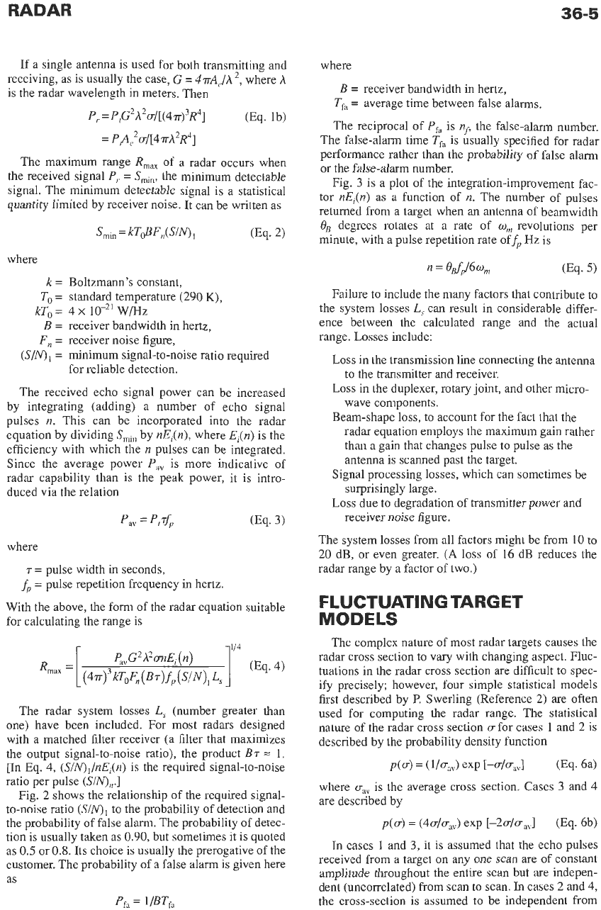
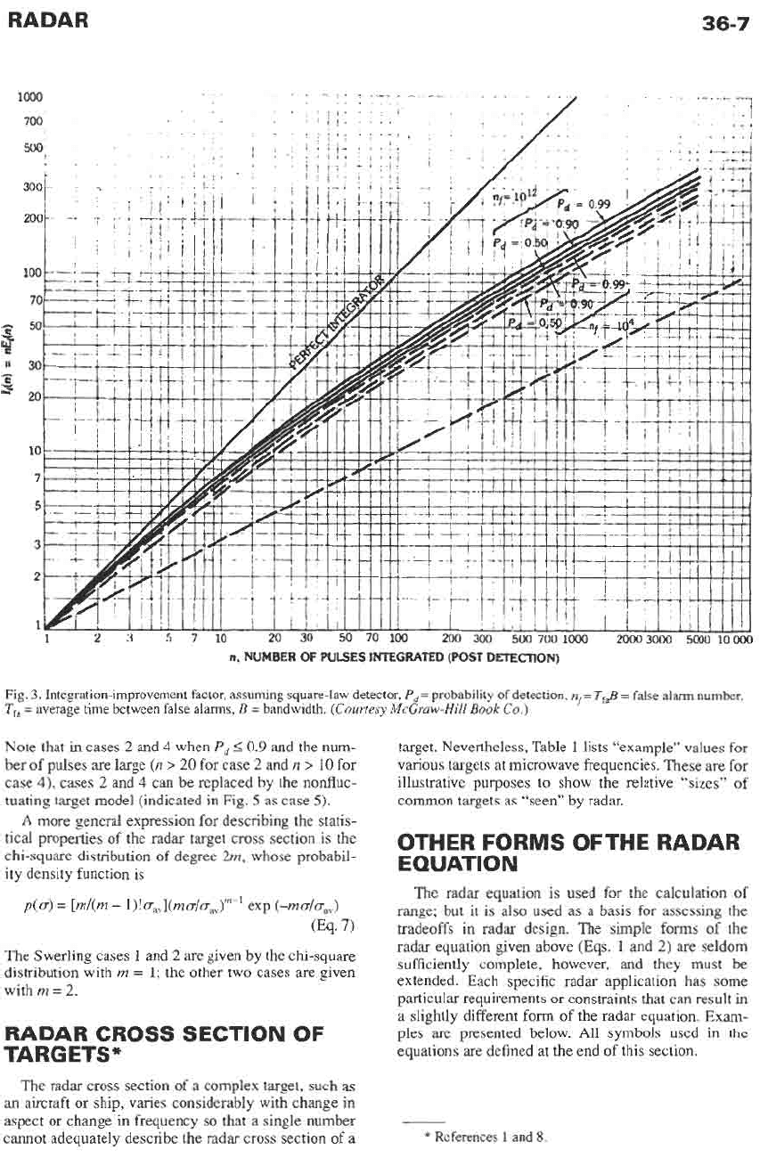
Fig.
3
is a plot
of
the integration-improvement fac-
tor
nE,(n)
as
a function of
n.
The number of pulses
returned from
a
target when an antenna of beamwidth
OB
degrees rotates at a rate of
w,
revolutions per
minute, with a pulse repetition rate offp
Hz
is
n
=
0Bfp/6w,
(Eq.
5)
Failure to include the many factors that contribute to
the system losses
L, can result in considerable differ-
ence between the calculated range and the actual
range. Losses include:
Loss in the transmission line connecting the antenna
to the transmitter and receiver.
Loss in the duplexer, rotary
joint,
and other micro-
wave components.
Beam-shape loss, to account for the fact that the
radar equation employs the maximum gain rather
than a gain that changes pulse to pulse as the
antenna is scanned past the target.
Signal processing losses, which can sometimes be
surprisingly large.
Loss due to degradation of transmitter power and
receiver noise figure.
The system losses from all factors might be from
10
to
20
dB, or even greater.
(A
loss of
16
dB reduces the
radar range by
a
factor of two.)
FLUCTUATING TARGET
MODELS
The complex nature of most radar targets causes the
radar cross section to vary with changing aspect. Fluc-
tuations in the radar cross section are difficult to spec-
ify precisely; however, four simple statistical models
first described by
P.
Swerling (Reference
2)
are often
used for computing the radar range. The statistical
nature of the radar cross section
u
for cases 1 and 2
is
described by the probability density function
~(4
=
(1bd exp
Eu/uav1
(Eq.
64
where
uav
is the average cross section. Cases
3
and
4
are described by
p(u)
=
(4u/raV)
exp [-2u/u,l
(Eq. 6b)
In
cases
1
and
3,
it is assumed that the echo pulses
received from a target on any one scan
are
of
constant
amplitude throughout the entire scan but are indepen-
dent (uncorrelated) from scan to scan.
In
cases
2
and
4,
the cross-section is assumed to be independent from
36-6
REFERENCE
DATA
FOR ENGINEERS
4
6
8
10
12
14
16
18
@/MI,
SIGNAL-TO-NOISE RATIO
IN
dB
Fig.
2.
Probability
of
detection for a sine wave in noise as a function of the signal-to-noise (power) ratio and the probability
of
false
alarm.
(Courtesy
McGruw-Hill
Book
Co.)
pulse to pulse. When these models
are
used, the signal-
to-noise ratios and the integration improvement factors
inserted in the radar equation are different from those
used for a constant cross section. The required values
can be found in several references (References
3-7);
however, a simple approximate method (Reference
1)
for most purposes can be obtained using Figs.
2,4,
and
5
with the following procedures:
A.
Find the signal-to-noise ratio from Fig.
2
corre-
sponding
to
the desired values
of
detection proba-
bility
P,
and false-alarm probability
P,
=
l/BTfa.
B.
From Fig.
4,
determine for the desired Swerling
case the correction factor to be applied to the signal-
to-noise ratio found from Fig.
2.
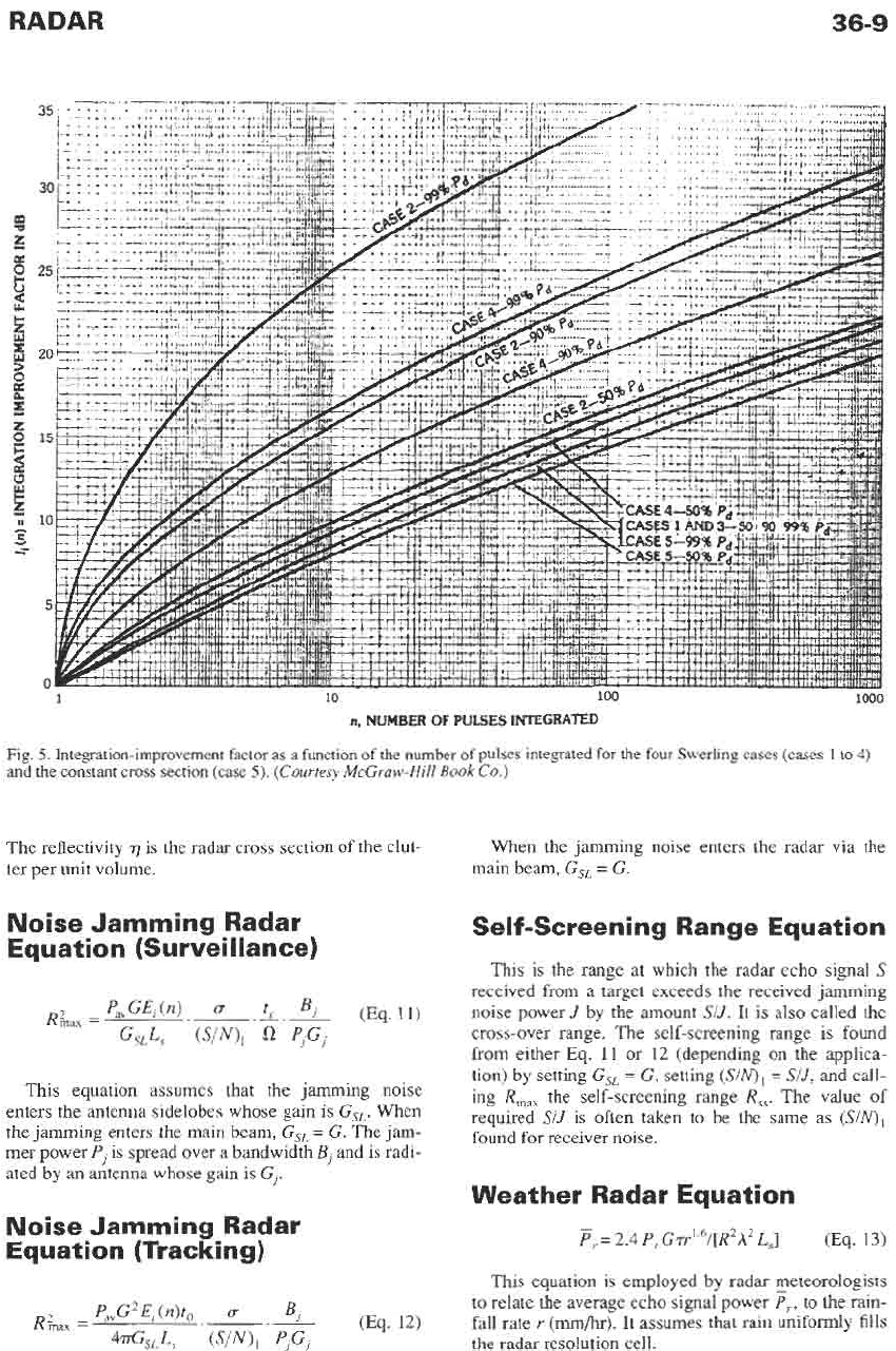
C.
Find the integration improvement factor nE,(n)
from Fig.
5.
RADAR
36-7
n,
NUMBER
OF
PULSES INTEGRATED (POST DETECTION)
Fig.
3.
Integration-improvement factor, assuming square-law detector,
P,
=
probability of detection,
ns=
Tf$
=
false
alarm number,
T,
=
average time between false alarms,
B
=
bandwidth.
(Courtesy
McGruw-Hill
Book
Co.)
Note that
in
cases
2
and
4
when
P,
I
0.9
and the num-
ber of pulses are large
(n
>
20
for case
2
and
n
>
10
for
case
4),
cases
2
and
4
can be replaced by the nonfluc-
tuating target model (indicated in Fig.
5
as case
5).
A
more general expression for describing the statis-
tical properties of the radar target cross section is the
chi-square distribution of degree
2m,
whose probabil-
ity density function is
The Swerling cases
1
and
2
are given by the chi-square
distribution with
m
=
1;
the other two cases are given
with
m
=
2.
RADAR CROSS SECTION OF
TARGETS*
The radar cross section of a complex target, such as
an
aircraft
or
ship, varies considerably with change in
aspect
or
change
in
frequency
so
that a single number
cannot adequately describe the radar cross section of a
target. Nevertheless, Table
1
lists “example” values for
various targets at microwave frequencies. These
are
for
illustrative purposes to show the relative “sizes” of
common targets as “seen” by radar.
OTHER FORMS OFTHE RADAR
EQUATIO
N
The radar equation is used for the calculation of
range; but it is also used as a basis for assessing the
tradeoffs in radar design. The simple forms of the
radar equation given above (Eqs.
1
and
2)
are seldom
sufficiently complete, however,
and
they must be
extended. Each specific radar application has some
particular requirements or constraints that can result in
a slightly different form of the radar equation.
Exam-
ples are presented below. All symbols used
in
the
equations are defined at the end of this section.
*
References
1
and
8.
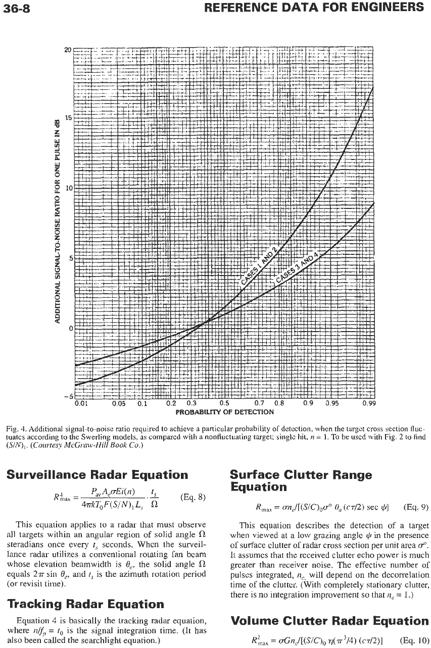
36-8
PROBABILITY
OF
DETECTION
Fig.
4.
Additional signal-to-noise ratio required to achieve
a
particular probability
of
detection, when the target cross section
fluc-
tuates according to the Swerling models,
as
compared with a nonfluctuating target; single hit,
n
=
1.
To
be used with Fig.
2
to find
(SIN),.
(Courtesy
McGraw-Hill
Book
Co.)
Survei
I
lance Radar Equation Surface Clutter Range
-
P,,A,cEi(n)
t,
Equation
(Eq.
8)
kkT,F(S/N),
L,
'6
R,,
=
m,/[(S/C),ao
0,
(42)
sec
@]
(Eq.
9)
RLx
=
This equation applies to a radar that must observe
all targets within an angular region of solid angle
steradians once every
t,
seconds. When the surveil-
lance radar utilizes a conventional rotating fan beam
whose elevation beamwidth is
e,,
the solid angle
a
equals
2n-
sin
e,,
and
t,
is the azimuth rotation period
(or revisit time).
This equation describes the detection of a target
when viewed at a low grazing angle
@
in the presence
of
surface clutter
of
radar cross section per unit area
go.
It assumes that the received clutter echo power is much
greater than receiver noise. The effective number
of
pulses integrated,
n,,
will depend on the decorrelation
time
of
the clutter. (With completely stationary clutter,
there is no integration improvement
so
that
ne
=
1.)
Volume Clutter Radar Equation
(Eq.
10)
Tracking Radar Equation
Equation
4
is basically the tracking radar equation,
where
nfp
=
to
is the signal integration time. (It has
also been called the searchlight equation.)
Ria,
=
OG~,/[(S~C)~
q(.rr3/4)
(cd2)I
RADAR
36-9
1
10
100
n.
NUMBER
OF
PULSES
INTEGRATED
1000
Fig.
5.
Integration-improvement factor as a function of the number of pulses integrated for
the
four Swerling cases (cases
1
to
4)
and
the
constant cross section (case
5).
(Courtesy
McGruw-Hill Book
Co.)
The reflectivity
7
is
the
radar cross section of the clut-
ter per unit volume.
When the jamming noise enters the radar via the
main beam,
G,
=
G.
Noise Jamming Radar
Equation (Surveillance)
This equation assumes that the jamming noise
enters the antenna sidelobes whose gain is
G,.
When
the jamming enters the main beam,
GsL
=
G.
The
jam-
mer power
Pi
is spread over
a
bandwidth
B,
and is radi-
ated by an antenna whose gain is
GI.
Noise Jamming Radar
Equation (Tracking)
Self-screening Range Equation
This is the range
at
which the radar echo signal
S
received from
a
target exceeds the received jamming
noise power
J
by the amount
SIJ.
It
is also called the
cross-over range. The self-screening range is found
from either Eq.
11
or
12
(depending on the applica-
tion) by setting
G,
=
G,
setting
(SIN),
=
SIJ,
and call-
ing
R,,,,
the self-screening range
Rss.
The value of
required
SIJ
is often taken to be the same
as
(SIN),
found for receiver noise.
Weather Radar Equation
P,=
2.4
P,
Gd61[R2A2
L,]
(Eq.
13)
This equation is employed by radar meteorologists
to relate the average echo signal power
P?,
to the rain-
fall rate
r
(-).
It assumes that rain uniformly fills
the radar resolution cell.

36-1
0
REFERENCE DATA FOR ENGINEERS
TBLE
1.
“EXAMPLE”
VALUES
OF
RADAR
CROSS
SECTION
Target
Conventional unmanned
Small single-engine aircraft
Small fighter or 4-passenger jet
Large fighter
Medium bomber or medium
jet
airliner
Large bomber or large
jet
airliner
Jumbo
jet
Helicopter
Small open boat
Small pleasure boat
Cabin cruiser
Ship, grazing angle greater
than zero
Pickup truck
Automobile
Bicycle
Man
Large bird
Medium bird
Large insect (locust)
Small insect
(fly)
winged missile
~
u
(square
meters)
0.1
1
2
6
20
40
100
3
0.02
2
10
Displacement tonnage
expressed in
m2
200
100
2
I
10-2
1
o-~
104
1
o-~
Synthetic Aperture Radar
Equation
_-
S
2Pavp,2uoacrar (Eq.
14)
N
-
e~~
F,
RS,
L,
sin*
+
This
equation relates
the
signal-to-noise ratio of a
resolution cell (sometimes called a pixel) with range
resolution
8,
and cross-range resolution
a,,
located
within a swath
S
centered at a range
R.
The above takes
account of the combined restriction
on
cross-range res-
olution and swath necessary to avoid ambiguities in
either range or cross range.
HF Over-the-Horizon Radar
Equation
The transmitting antenna gain
G,
and the receiving
antenna gain
G,.
are shown separate since two different
antennas are often used for transmit and receive. The
propagation loss is accounted for by
Fp
(number less
than unity), and
T,
is the coherent processing time. The
noise power per unit bandwidth
No
(W/Hz) at the
receiver is determined by external noise.
Symbol
Definitions
The symbols used in the above radar equations are
A,
=
antenna effective aperture in square meters
B
=
receiver bandwidth in hertz
Bj
=
jammer bandwidth in hertz
c
=
velocity of propagation in meters/second
Sc,
=
cross-range resolution
in
meters
8,
=
range resolution in meters
E,@)
=
efficiency in integrating
n
pulses
r]
=
volume clutter of reflectivity, or radar cross
f
=
radar frequency in hertz
fp
=
pulse repetition frequency in hertz
F,
=
receiver noise figure
Fp
=
propagation factor
G
=
antennagain
Gj
=
jammer antenna gain
G,.
=
radar receiving antenna gain
G,
=
antenna sidelobe gain
G,
=
transmitting antenna gain
defined as follows.
section of clutter per unit volume, in meters-’
k
=
Boltzmann’s constant
=
1.38
x
jouleskelvin
L,
=
systemlosses
A
=
wavelength in meters
n
=
number of echo pulses received per target
ne
=
effective number
of
pulses integrated
No
=
noise power per unit bandwidth
fl
=
solid angular region (steradians) of radar
coverage
P,
=
average power in watts
5
=
jammer power in watts
P,.
=
average received signal power in watts
P,.
=
received signal power
in
watts
P,
=
peak power in watts
=
grazing angle
r
=
rainfall rate in millimeters/hour
R
=
range inmeters
R,,,
=
maximum radar range in meters
pa
=
antennaefficiency
(SIC),
=
minimum signal-to-clutter ratio necessary to
detect a target with a specified probability of
detection and probability of false alarm, for a
single pulse
SIN
=
signal-to-noise ratio in a
SAR
resolution cell
(SIN),
=
minimum signal-to-noise ratio necessary
to
detect a target with a specifiedprobability of
detection and probability of false alarm, for
a single pulse
S,
=
swath width in meters
u
=
radar cross section
of
target
in
square meters
uo
=
radar cross section of surface clutter per unit
area
t,
=
scan time, or revisit time,
in
seconds
to
=
n/fp
=
signal integration time in seconds
I",
=
coherent processing time in seconds
To
=
standard temperature
=
290
K
r
=
pulse width in seconds
0,
=
azimuth beamwidth in radians
0,
=
elevation beamwidth in radians
v
=
velocity
in
meters/second
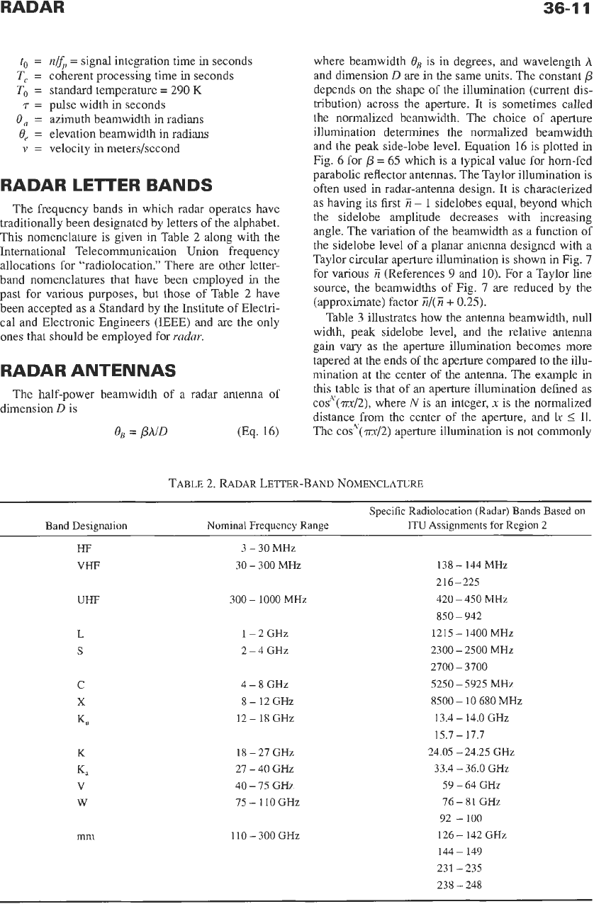
RADAR
LETTER
BANDS
The frequency bands in which radar operates have
traditionally been designated by letters of the alphabet.
This nomenclature is given in Table 2 along with the
International Telecommunication Union frequency
allocations for "radiolocation." There are other letter-
band nomenclatures that have been employed in the
past
for various purposes, but those of Table 2 have
been accepted as
a
Standard by the Institute of Electri-
cal and Electronic Engineers (IEEE) and are the only
ones that should be employed
for
radar.
RADAR ANTENNAS
The half-power beamwidth of a radar antenna of
dimension
D
is
OB
=
PAID
where beamwidth
OB
is in degrees, and wavelength
A
and dimension
D
are in the same units. The constant
p
depends on the shape of the illumination (current dis-
tribution) across the aperture. It is sometimes called
the normalized beamwidth. The choice of aperture
illumination determines the normalized beamwidth
and the
peak
side-lobe level. Equation 16 is plotted in
Fig.
6
for
/?
=
65 which is
a
typical value for horn-fed
parabolic reflector antennas. The Taylor illumination is
often used in radar-antenna design. It is characterized
as
having its first
7i
-
1
sidelobes equal, beyond which
the sidelobe amplitude decreases with increasing
angle. The variation of the beamwidth
as
a
function of
the sidelobe level of a planar antenna designed with a
Taylor circular aperture illumination is shown in Fig.
7
for various
Z
(References
9
and 10). For
a
Taylor line
source, the beamwidths of Fig.
7
are reduced by the
(approximate) factor
Z/(Z
+
0.25).
Table
3
illustrates how the antenna beamwidth, null
width, peak sidelobe level, and the relative antenna
gain vary as the aperture illumination becomes more
tapered at the ends of the aperture compared to the illu-
mination at the center of the antenna. The example in
this table
is
that of an aperture illumination defined as
c0s'~~(?rx/2), where
N
is an integer,
x
is the normalized
distance from the center of the aperture, and
Ix
4
11.
The cos"(m/2) aperture illumination is not commonly
TABLE
2.
RADAR
LETTER-BAND NOMENCLATURE
Specific Radiolocation (Radar) Bands Based on
Band Designation Nominal Frequency Range
ITU
Assignments
for
Region
2
HF 3
-
30 MHz
VHF
30
-
300 MHz
138
-
144 MHz
2 16
-
225
300
-
1000 MHz
420
-
450 MHz
850
-
942
UHF
L
1-2GHz
1215
-
1400 MHz
S
2-4GHz
2300
-
2500 MHz
C
4-8GHz 5250
-
5925 MHz
X
8-12GHz
8500
-
10
680 MHz
2700
-
3700
12
-
18 GHz
13.4
-
14.0 GHz
K"
15.7
-
17.7
K
18
-
27 GHz 24.05
-
24.25 GHz
27
-
40 GHz
33.4
-
36.0 GHz
Ka
V
40
-
75 GHz
59
-
64 GHz
W
75
-
110 GHz
76
-
81 GHz
92
-200
mm 110-300GHz 126
-
142 GHz
144
-
149
231
-
235
238
-
248