Middleton W.M. (ed.) Reference Data for Engineers: Radio, Electronics, Computer and Communications
Подождите немного. Документ загружается.

38-1
0
REFERENCE
DATA
FOR ENGINEERS
the same source to the same load through a transducer
(network, channel). The definition may be applied to
the loss or gain effect caused by the insertion
of
a gain
element (repeater) or equalizer into a transmission
channel. The concept is equally applicable to the chan-
nel as a whole.
Transducer Loss-The ratio of the maximum
power available from a source to the power delivered
by that source to a load through a transducer (network,
channel). The transducer loss of a channel differs from
the insertion loss only because the maximum power
from the source is substituted for
the
power from that
source to that load.
Echo
and
Stability
Return Loss-A measure of the match between
the
two impedances on either side of a junction point.
Return loss is defined by:
RL
(dB)
=
20
log,,
+
ZJ/(Z,
-ZJI,
where
2,
and
Z2
are the complex impedances
of
the
two halves of the circuit. When the impedances are not
matched, the junction becomes a reflection point. The
return loss expresses the ratio
of
incident to reflected
signal power. It is often made effectively infinite by
introducing echo cancellation into a four-wire portion
of the circuit.
Echo Return Loss (ERL)-The weighted power-
averaged return loss at the reflection point. The ERL
expresses in decibels the ratio of the power of a broad-
band incident signal
to
that of the correspondingly
broadband reflected signal. Both powers are measured
through a weighting network covering the band
of
approximately
500-2500
Hz.
Singing Return Loss-The same as echo return
loss, but over a narrower band near the lower or upper
edge
of
the voice band, e.g.,
200-500
Hz
or
2500-
3200
Hz.
The extremes
of
the band are used because
singing usually takes place there.
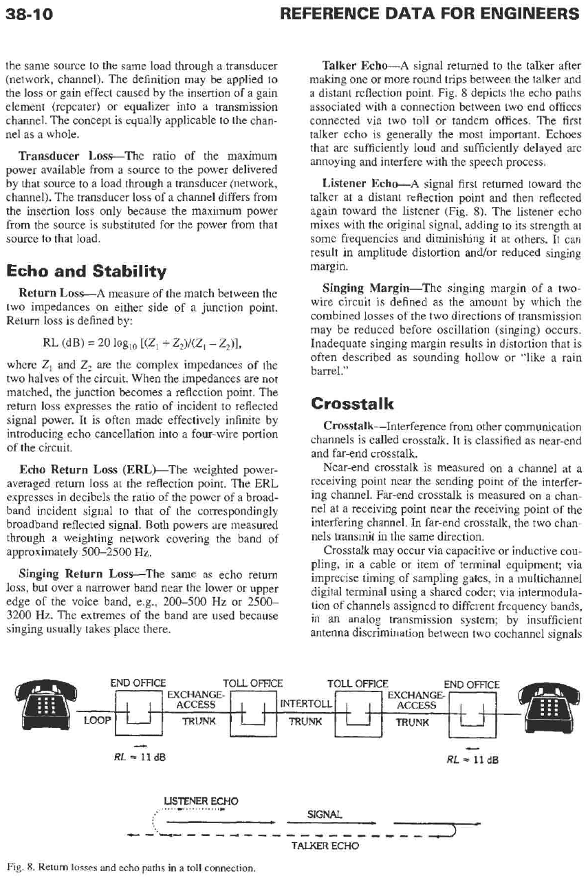
Talker Echo---A signal returned
to
the talker after
making one or more round trips between the talker and
a distant reflection point. Fig.
8
depicts the echo paths
associated with a connection between two end offices
connected via two toll or tandem offices. The first
talker echo is generally the most important. Echoes
that are sufficiently loud and sufficiently delayed are
annoying and interfere with the speech process.
Listener Echce-A signal first returned toward the
talker at a distant reflection point and then reflected
again toward the listener (Fig.
8).
The listener echo
mixes with the original signal, adding to its strength at
some frequencies and diminishing
it
at others. It can
result in amplitude distortion and/or reduced singing
margin.
Singing Margin-The singing margin of a two-
wire circuit is defined as the amount by which the
combined losses of the two directions of transmission
may be reduced before oscillation (singing) occurs.
Inadequate singing margin results in distortion that is
often described as sounding hollow or “like a rain
barrel.”
Crosstalk
Crosstalk-Interference from other communication
channels is called crosstalk. It is classified as near-end
and far-end crosstalk.
Near-end crosstalk is measured on a channel at a
receiving point near the sending point
of
the interfer-
ing channel. Far-end crosstalk is measured
on
a chan-
nel at a receiving point near the receiving point
of
the
interfering channel.
In
far-end crosstalk, the two chm-
nels transmit in the same direction.
Crosstalk may occur via capacitive or inductive cou-
pling, in a cable or item of terminal equipment; via
imprecise timing
of
sampling gates, in a multichannel
digital terminal using a shared coder; via intermodula-
tion
of
channels assigned to different frequency bands,
in
an
analog transmission system; by insufficient
antenna discrimination between two cochannel signals
RL
=
11
dB
-
RL
-
11
dB
USTENER
ECHO
......
.............
SlGNAL
e-------------
----
---
TALKER
ECHO
Fig.
8.
Return
losses and
echo
paths
in
a
toll
connection.
COMMON CARRIER TRANSMISSION
38-1
I
using different polarizations, in a radio system; etc.
Crosstalk between digital transmission lines manifests
itself by degrading the error margin of one line or both.
Crosstalk is also classed as intelligible and
unintelligible. Intelligible crosstalk can be understood
by the listener; because it diverts attention, it has more
interfering effect than unintelligible cross talk.
Crosstalk into a voice-frequency circuit from adjacent
voice-frequency circuits may be intelligible. Crosstalk
due to incomplete suppression of sidebands, or to
intermodulation of two or more frequency-multiplexed
channels, is generally unintelligible. Such crosstalk is
often classed as miscellaneous noise. Where a cou-
pling path between transmission facilities gives rise to
intelligible or nearly intelligible cross talk, normal
practice is to design the system
so
that the probability
that a customer will hear a “foreign” conversation does
not exceed one percent.
Digital Performance
On
digital facilities and services, transmission qual-
ity is commonly defined in terms of three parameters:
Bit Error Ratio (BER)-The number of errors in a
given number of transmitted bits (e. g., one error in
10’
Errored Second (ES)-A one-second transmission
or a
BER
of
IO-’).
interval that contains one or more bit errors.
Error-Free Second (EFS)-The converse of ES.
Severely Errored Second (SEStConventionally,
a one-second transmission interval having a BER of
As examples, the following performance objectives
or more.
and limits have been used:
Parameter
ES
EFS
SES
BER
% %
Perday
DSL Design
LocalDS1 Svc. 216 99.75 15
LocalDS3 Svc. 2x
lo-’’
432 99.5 15
Objective
1
o-’
FACILITIES
Wire
Multiconductor copper cable is widely used in pair
counts up to 2700 or even higher. Cable insulated with
paper pulp or polyethylene, in sizes of 22, 24, and 26
American Wire Gauge, are most common for voice-
band,
DSL,
and carrier frequencies up to several mega-
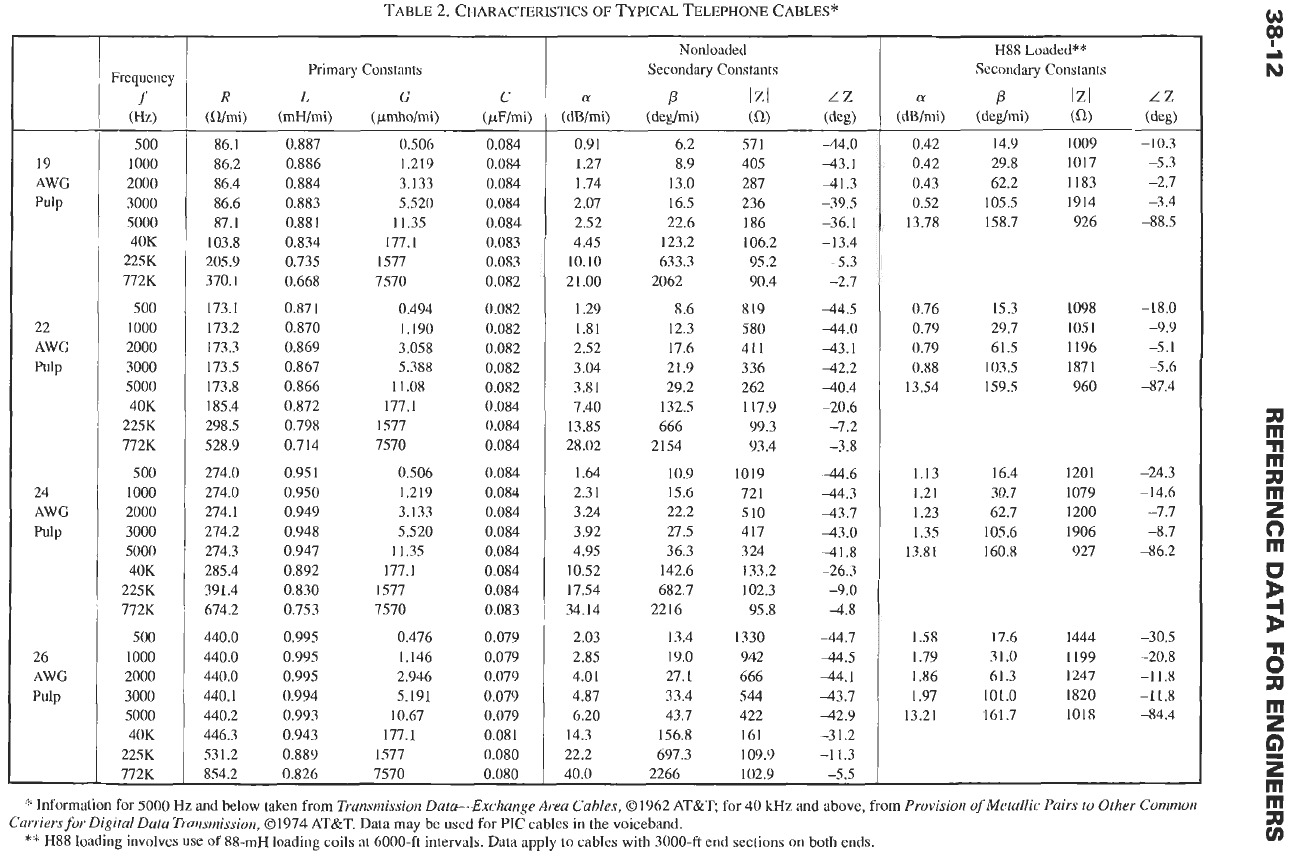
hertz. The transmission characteristics of typical
paired cables are given in Table 2. The data cover the
voiceband and higher frequencies:
40
kHz
(DSL),
225
kHz
(HDSL),
and 772
kHz
(T1 carrier spans). While
most longer loops and interoffice
trunks
utilize carrier
transmission, it is possible to use loaded cable, by
itself or with voice-frequency repeaters. Open-wire
facilities have generally disappeared, even in rural
areas. For carrier transmission frequencies up to 60 MHz,
multiple coaxial cable facilities have been used. Such
cables have occasionally been converted to digital
transmission.
Repeaters
General-If cable loss exceeds limits, it is neces-
sary
to add gain to the circuit. Amplifiers for this pur-
pose are termed “voice-frequency repeaters.” They are
used mainly for transmission-range extension
on
some
local loops, special-service circuits, etc. Two types
of
repeater
are
typically used: four-wire and hybrid. Both
provide independent gain and equalization for each
direction of transmission.
Fou
r-VVi
re
Repeaters
Four-wire repeaters are associated with four-wire
cable facilities, generally as voice-frequency exten-
sions of carrier transmission systems in full-duplex
data circuits and the like. The associated repeaters can
be used in applications requiring more gain and/or
equalization than can be obtained with two-wire
repeatered facilities.
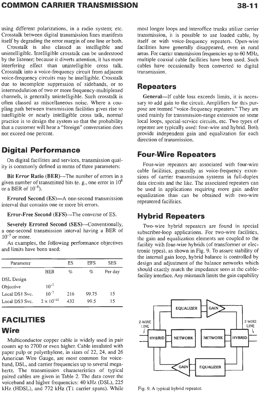
Hybrid Repeaters
Two-wire hybrid repeaters are found in special
subscriber-loop applications. For two-wire facilities,
the gain and equalization elements are coupled
to
the
facility with four-wire hybrids
(of
transformer or elec-
tronic types), as shown in Fig.
9.
To assure stability of
the internal gain loop, hybrid balance is controlled by
design and adjustment of the balance networks which
should exactly match the impedance seen at the cable-
facility interface. Any mismatch limits the gain capability
2-WIRE 2-WIRE
LINE LINE
I
-\
-
-
-
-
HYBRID NETWORK NETWORK HYBRID
-
-
-
-
Fig.
9.
A
typical hybrid repeater.
19
AWG
Pulp
22
AWG
Pulp
24
AWG
26
AWG
Pulp
Frequency
f
(W
500
1000
2000
3000
5000
40K
225K
772K
500
1000
2000
3000
5000
40K
225K
77213
500
1000
2000
3000
5000
40K
2253
772K
500
1000
2000
3000
5000
40K
22513
772K
TABLE
2.
CHARACTERISTICS
OF
TYPICAL TELEPHONE CABLES*
Primary Constants
R
1.
G
C
(a/mi) (mH/mi)
(pmho/mi)
(pF/mi)
86.1
86.2
86.4
86.6
87.1
103.8
205.9
370.1
173.1
173.2
173.3
173.5
173.8
185.4
298.5
528.9
274.0
274.0
274.1
274.2
274.3
285.4
391.4
674.2
440.0
440.0
440.0
440.1
440.2
446.3
531.2
0.887
0.886
0.884
0.883
0.881
0.834
0.735
0.668
0.871
0.870
0.869
0.867
0.866
0.872
0.798
0.714
0.951
0.950
0.949
0.948
0.947
0.892
0.830
0.753
0.995
0.995
0.995
0.994
0.993
0.943
0.889
0.506
1.219
3.133
5.520
11.35
177.1
1577
7570
0.494
1.190
3.058
5.388
1
1
.08
177.1
1577
7570
0.506
1.219
3.133
5.520
1
1.35
177.1
1577
7570
0.476
1.146
2.946
5.191
10.67
177.1
1577
0.084
0.084
0.084
0.084
0.084
0.083
0.083
0.082
0.082
0.082
0.082
0.082
0.082
0.084
0.084
0.084
0.084
0.084
0.084
0.084
0.084
0.084
0.084
0.083
0.079
0.079
0.079
0.079
0.079
0.081
0.080
854.2 0.826 7570 0.080
~
Nonloaded
Secondary Constants
a
P
IZI
LZ
(dB/mi)
(deglmi)
(a)
(deg)
0.91
1.27
1.74
2.07
2.52
4.45
10.10
21.00
1.29
1.81
2.52
3.04
3.81
7.40
13.85
28.02
1.64
2.31
3.24
3.92
4.95
10.52
17.54
34.14
2.03
2.85
4.01
4.87
6.20
14.3
22.2
40.0
6.2
8.9
13.0
16.5
22.6
123.2
633.3
2062
8.6
12.3
17.6
21.9
29.2
132.5
666
21.54
10.9
15.6
22.2
27.5
36.3
142.6
682.7
2216
13.4
19.0
27.1
33.4
43.7
156.8
697.3
2266
57 1
405
287
23
6
186
106.2
95.2
90.4
819
580
411
336
262
117.9
99.3
93.4
1019
721
510
417
324
133.2
102.3
95.8
1330
942
666
544
422
161
109.9
-44.0
43.1
41.3
-39.5
-36.1
-13.4
-5.3
-2.7
-44.5
44.0
43.1
42.2
40.4
-20.6
-7.2
-3.8
-44.6
44.3
43.7
43.0
41.8
-26.3
-9.0
4.8
44.7
44.5
-44.1
43.7
42.9
-3 1.2
-1
1.3
102.9 -5.5
H88
Loaded**
Secondary Constants
a
P
(dB/mi) (deglmi)
0.42
0.42
0.43
0.52
13.78
0.76
0.79
0.79
0.88
13.54
1.13
1.21
1.23
1.35
13.81
1.58
1.79
1.86
1.97
13.21
14.9
29.8
62.2
105.5
158.7
15.3
29.7
61.5
103.5
159.5
16.4
30.7
62.7
105.6
160.8
17.6
31.0
61.3
101.0
161.7
I009
1017
1183
1914
926
1098
1051
1196
1871
960
1201
1079
1200
1906
927
1444
1199
1247
1820
1018
-10.3
-5.3
-2.7
-3.4
-88.5
-18.0
-9.9
-5.1
-5.6
-87.4
-24.3
-14.6
-7.7
-8.7
-86.2
-30.5
-20.8
-1 1.8
-11.8
-84.4
*
In€ormation
€or
5000
Hz
and below taken
from
Transmission DateExchange Area Cables,
01
962
AT&T;
for
40
lcHz
and above, from
Provision
of
Metallic Pairs to Other Common
**
H88
loading involves
use
of
88-mH
loading coils at
6000-11
intervals. Data apply
to
cables with
3000-ft
end sections on both ends.
Carriers for Digital Data Transmission,
01974
AT&T.
Data may
be
used for
PIC
cables in
the
voiceband.
cn)
N
so
a
a
rn
n
rn
311
rn
2
0
rn
:
3
B
n
rn
2
0
z
rn
m
311
ua
COMMON CARRIER TRANSMISSION
38-1
3
of the repeater. Where precise automatic balancing of
the hybrid is desired, a design may be used in which
the four-wire path includes a digital coder and decoder
in each direction, along with
a
digital echo canceller.
The canceller provides the equivalent of a very high
degree of hybrid balance.
Fiber-optic Facilities
Glass-fiber optic transmission facilities (see Chapter
22) have generally displaced wire facilities
as
a more
economical and higher-performance alternative for
carrier transmission. Fiber-optic facilities are used for
both digital trunk carrier and digital subscriber carrier
systems and, in sizes up to 864 fibers, are finding
direct application in subscriber loops as well. Trans-
mission speeds up to OC-192
(10
Gb/s) on a single
wave length
are
commonplace in the long-haul envi-
ronment, and extensions of capacity are available by
use of wavelength-division multiplexing (WDM), in
which 40 wavelengths or more may be carried simulta-
neously. Optical amplifiers may be used on particu-
larly long fiber lines, especially in submarine cables.
Fiber facilities, in “self-healing” ring configurations,
are often used to improve service reliability.
Carrier Systems
General-As suggested before, when many tele-
communications channels are needed between two
points, it is usual to use
a
carrier system to multiplex
many channels over one medium. Media used for such
systems include glass fibers, cable pairs, and micro-
wave radio (terrestrial or satellite).
Multiplexing Techniques-Two basic techniques
are
used for the transmission of multiple channels over
a single transmission medium:
Time-division systems,
usually digital, in which each
communication channel is allotted a discrete time slot
within
a
sampling frame, occupying essentially the
entire wideband frequency spectrum for the allotted
time. The original practice was to multiplex directly,
with a fixed destination; another technique of growing
importance is to convert the bitstream into packets
for transmission and routing, usually to multiple desti-
nations.
Frequency-division systems,
in which a unique band
of frequencies within the wide frequency spectrum of
the medium is allotted to each communication channel
on
a
continuous-time basis. This technique is found
mainly in radio systems, and in wavelength-division
multiplexing in fiber-optic systems.
Modulation Techniques-Several modulation
methods may be employed with either
of
the multi-
plexing techniques. Pulse-code modulation is the most
common time-division modulation technique, although
adaptive differential PCM, delta modulation, and other
techniques are also found occasionally. Several fre-
quency-division modulation techniques are in use,
including frequency modulation and amplitude modu-
lation, both double- and single-sideband. See Chapters
23 and 24 for
a
more detailed discussion of modulation
techniques.
Trunk Carrier-Trunk carrier systems operate
between switching offices, using either trunk termina-
tions built into digital switches (now usual) or discrete
carrier terminals (channel banks) that deliver analog
voice channels.
Circuit Multiplication-For voice connections
through digital submarine cables, digital circuit-multi-
plication systems may transcode the 64-kb/s speech
signal to 32 kb/s and perform speech interpolation
(connecting a talker to the channel only when speech
is present). This yields
a
typical circuit multiplication
of
51.
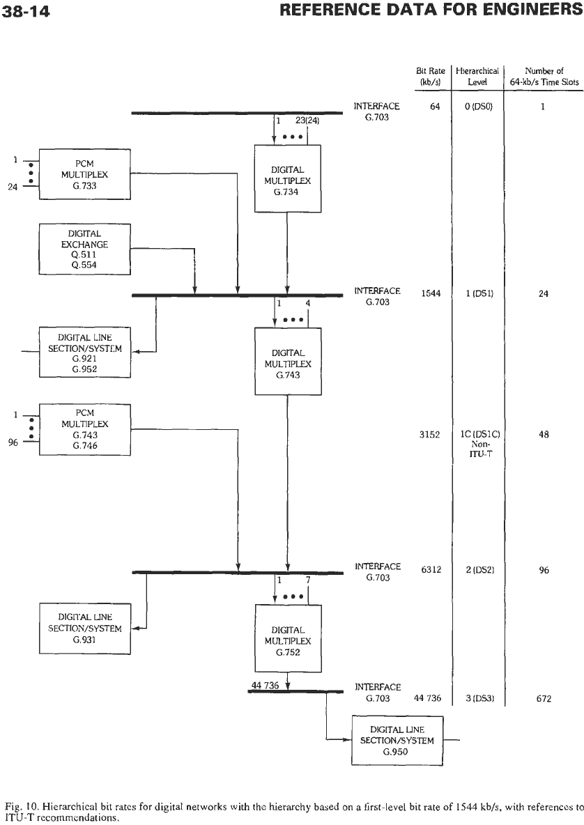
Common-Carrier HierarchiesThere are several
agreed-upon bundle sizes or multiplex levels for carry-
ing channels in common-carrier systems. Most
of
the
standards are covered in ITU-T documents.
In
digital
transmission, the basic entity
is
a
64 kb/s channel in
which the nominal 4-kHz voice signal has been filtered
(to minimize aliasing) and sampled at
8
kHz,
with
each sample encoded into eight bits. Digital data
at
up
to 64 kb/s can be substituted for the digitized voice-
band signal. Fig.
10
gives the digital hierarchy levels
corresponding to bit rates, and the numbers of usable
64-kb/s time slots, recommended by ITU-T. The figure
is couched in terms of the basic DS
1
transmission rate
of 1544 kb/s
as
used in North America. Not defined by
ITU-T, but also occasionally used in the United States
and Canada, is
a
DSlC level intermediate between the
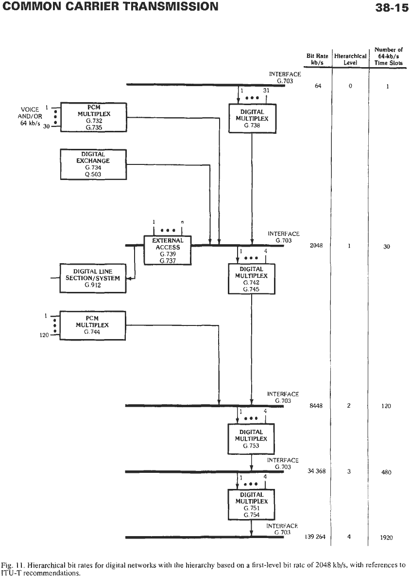
first and second levels. Fig. 11 gives the corresponding
hierarchy for the basic El rate of 2048 kb/s
as used in
Europe. The figures diagram the levels, multiplexes,
digital line systems, and references to ITU-T docu-
ments that give more detailed specifications for the
two generic hierarchies. These various hierarchy levels
are not timed from
a
common clock; they are termed
the Plesiochronous Digital Hierarchy.
In
North America most local interoffice trunks, and
virtually all toll connecting trunks, are digital due to
the synergy between digital transmission and switch-
ing. At digital-signal levels
1
and 2, the bit stream may
be carried on wire pairs with regenerators, or via chan-
nels on
a
higher-level multiplex system using fiber or
radio
as
its base facility. Radio may be used for higher
bit rates between
45
and 155
Mb/s,
and optical-fiber
media up to 40 Gb/s. Rapid advances in technology,
such
as
low-loss/low-dispersion single-mode fiber,
have led to the introduction of additional bit rates into
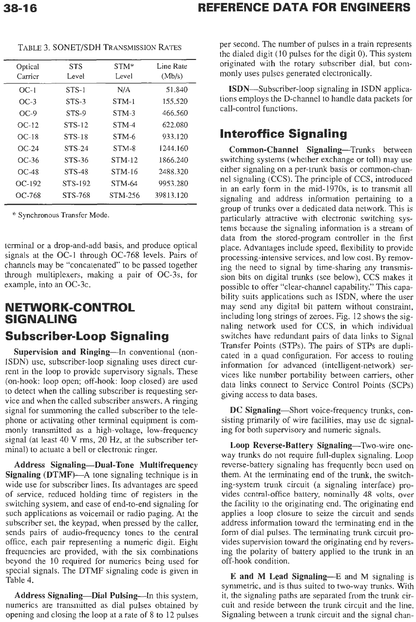
the digital hkirchy. The Synchronous Optical Net-
work (SONET) [or, in ITU-T terms, Synchronous
Digital Hierarchy] involves ten unique transmission
speeds for use on fiber or suitable digital microwave
systems. These are synchronous multiples of 51.840
Mb/s,
as listed in Table
3.
SONET multiplexers accept
and deliver DSl- and DS3-level signals, on either
a
38-1
4
REFERENCE
DATA
FOR
ENGINEERS
INTERFACE
1
23(24) G.703
I
DIGITAL
DIGITAL
MULTIPLEX
G.734
I
t t
f
INTERFACE
I1
4
1
G.703
SECTION/SYSTEM
G.921
DIGITAL LINE
SECTION/SYSTEM
G.931
DIGITAL
MULTIPLEX
G.743
I
I
INTERFACE
G.703
1
DIGITAL
MULTIPLEX
G.752
+
INTERFACE
G.703
Bit
Rate
nib/sl
64
-
1544
3152
6312
44 736
DIGITAL LINE
SECTION/SYSTEM
G.950
{ierarchical
Level
0
(DSO)
1
(DS1)
1C
(DSIC:
Non-
ITU-T
2 (DS2)
3
(DS3)
Number
of
i4-kb/s Time
Slots
1
24
48
96
672
Fig.
10.
Hierarchical bit rates for digital networks
with
the hierarchy based
on
a first-level bit rate of 1544 kbh, with references to
ITU-T
recommendations.
COMMON CARRIER TRANSMISSION
VOICE
-
64
kb/s
3oL
AND/OR
:
38-1
5
PCM
MULTIPLEX
G.732
G.735
INTERFACE
G.703
1
31
*Ob
DIGITAL
MULTIPLEX
G.738
DIGITAL
EXCHANGE
G.734
Q.503
ACCESS
G.739
SECTION/SYSTEM
G.912
PCM
I
INTERFACE
G.703
DIGITAL
MULTIPLEX
G 742
INTERFACE
DIGITAL
MULTIPLEX
INTERFACE
DIGITAL
MULTIPLEX
G.751
INTERFACE
G.703
Bit
Rate
kb/s
-
64
2048
8448
34 368
139 264
ierarchical
Level
-
0
1
2
3
4
number
of
64-kbIs
lime
Slots
1
30
120
480
1920
Fig.
11.
Hierarchical bit rates for digital
networks
with the hierarchy based
on
a first-level
bit
rate
of
2048
kb/s,
with references to
ITU-T
recommendations.
38-1
6
REFERENCE
DATA
FOR ENGINEERS
TABLE 3. SONET/SDH
TRANSMISSION
RATES
Optical
STS STM*
Line Rate
Carrier
Level Level
WJIs)
oc-1
OC-3
OC-9
oc-12
oc-
18
OC-24
OC-36
OC-48
OC-192
OC-768
STS-1
STS-3
STS-9
STS-12
STS-18
STS-24
STS-36
STS-48
STS-192
STS-768
NIA
STM-1
STM-3
STM-4
STM-6
STM-8
STM-12
STM-16
STM-64
STM-256
51.840
155.520
466.560
622.080
933.120
1244.160
1866.240
2488.320
9953.280
39813.120
*
Synchronous Transfer
Mode.
terminal or a drop-and-add basis, and produce optical
signals at the OC-1 though OC-768 levels. Pairs of
channels may be “concatenated”
to
be passed together
through multiplexers, making a pair of OC-~S, for
example, into an OC-3c.
N
ETWORK-CONTROL
SIGNALING
S
u
bsc r
i
be
r-
Lo
o
p
S
i
g n a
I
i
n g
Supervision and Ringing-In conventional (non-
ISDN) use, subscriber-loop signaling uses direct cur-
rent in the loop
to
provide supervisory signals. These
(on-hook: loop open; off-hook loop closed)
are
used
to detect when the calling subscriber is requesting ser-
vice and when the called subscriber answers. A ringing
signal for summoning the called subscriber to the tele-
phone or activating other terminal equipment is com-
monly transmitted as a high-voltage, low-frequency
signal (at least
40
V
rms,
20
Hz, at the subscriber ter-
minal) to actuate a bell or electronic ringer.
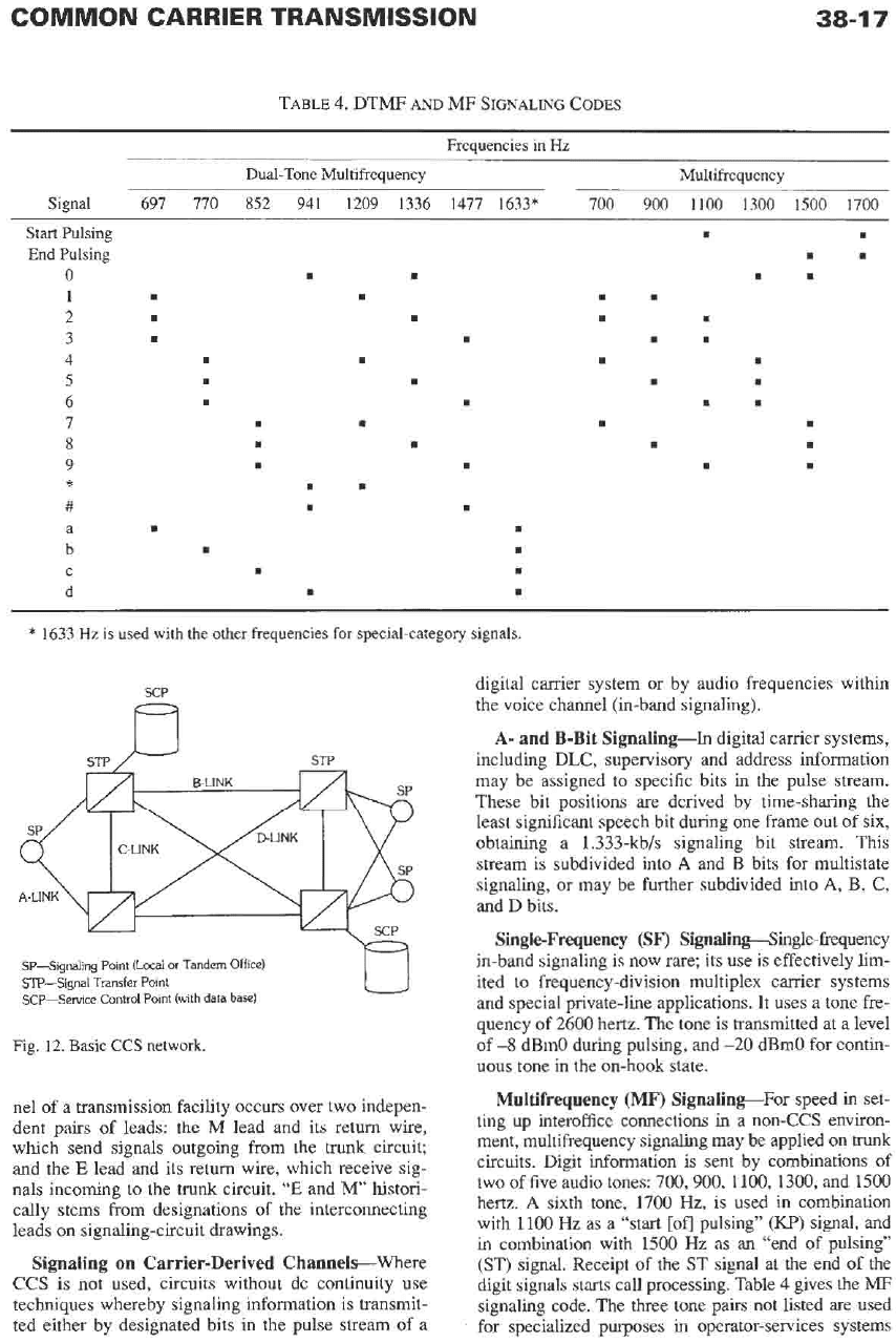
Address Signaling-Dual-Tone Multifrequency
Signaling (DTMF)-A tone signaling technique is in
wide use for subscriber lines. Its advantages are speed
of
service, reduced holding time
of
registers in the
switching system, and ease of end-to-end signaling for
such applications as voicemail or radio paging. At the
subscriber set, the keypad, when pressed by the caller,
sends pairs of audio-frequency tones to the central
office, each pair representing a numeric digit. Eight
frequencies are provided, with the six combinations
beyond the
10
required for numerics being used for
special signals. The DTMF signaling code
is
given in
Table
4.
Address Signaling-Dial Pulsing-In this system,
numerics are transmitted as dial pulses obtained by
opening and closing the loop at a rate of
8
to
12
pulses
per second. The number
of
pulses in a train represents
the dialed digit
(10
pulses for the digit
0).
This system
originated with the rotary subscriber dial, but com-
monly uses pulses generated electronically.
ISDN-Subscriber-loop signaling in ISDN applica-
tions employs the D-channel
to
handle data packets for
call-control functions.
Interoffice Signaling
Common-Channel Signaling-Trunks between
switching systems (whether exchange or toll) may use
either signaling on a per-trunk basis or common-chan-
ne1 signaling (CCS). The principle of CCS, introduced
in an early form in the mid-l970s, is
to
transmit all
signaling and address information pertaining to a
group of trunks over a dedicated data network. This is
particularly attractive with electronic switching sys-
tems because the signaling information is a stream of
data from the stored-program controller in the first
place. Advantages include speed, flexibility to provide
processing-intensive services, and low cost. By remov-
ing the need to signal by time-sharing any transmis-
sion bits on digital
trunks
(see below), CCS makes it
possible
to
offer “clear-channel capability.” This capa-
bility suits applications such as ISDN, where the user
may send any digital bit pattern without constraint,
including long strings of zeroes. Fig.
12
shows the sig-
naling network used for CCS, in which individual
switches have redundant pairs of data links to Signal
Transfer Points (STPs). The pairs of STPs are dupli-
cated in a quad configuration. For access
to
routing
information for advanced (intelligent-network) ser-
vices like number portability between carriers, other
data links connect to Service Control Points (SCPs)
giving access to data bases.
DC Signaling-Short voice-frequency
trunks,
con-
sisting primarily of wire facilities, may use dc signal-
ing for both supervisory and numeric signals.
Loop
Reverse-Battery Signaling-Two-wire one-
way trunks do not require full-duplex signaling. Loop
reverse-battery signaling has frequently been used on
them. At the terminating end of the trunk, the switch-
ing-system trunk circuit (a signaling interface) pro-
vides central-office battery,
nominally
48
volts, over
the facility to the originating end. The originating end
applies a loop closure
to
seize the circuit and sends
address information toward the terminating end in the
form
of
dial pulses. The terminating
trunk
circuit pro-
vides supervision toward the originating end by revers-
ing the polarity
of
battery applied to the
trunk
in an
off-hook condition.
E
and M Lead Signaling-E and
M
signaling
is
symmetric, and is thus suited
to
two-way
trunks.
With
it, the signaling paths
are
separated from the
trunk
cir-
cuit and reside between the
trunk
circuit and the line.
Signaling between a trunk circuit and the signal chan-
COMMON CARRIER TRANSMISSION
38-1
7
TABLE
4.
DTMF
AND
MF
SIGNALING
CODES
Frequencies in
Hz
Dual-Tone Multifrequency Multifrequency
Signal
697 770 852 941 1209 1336 1477 1633* 700 900 1100
1300
1500 1700
Start
Pulsing
End Pulsing
0
1
2
3
4
5
6
7
8
9
#
a
b
d
*
C
*
1633
Hz
is
used
with the other frequencies for special-category signals.
SCP
Fl
STP
/u
STP
digital carrier system or by audio frequencies within
the voice channel (in-band signaling).
A-
and B-Bit Signaling-In digital carrier systems,
including DLC. swervisorv and address information
v
II
may be assigned to specific bits in
the
pulse stream.
These bit positions
are
derived by time-sharing the
least significant speech bit during one frame
out
of six,
obtaining a 1.333-kb/s signaling bit stream. This
stream is subdivided into
A
and
B
bits for multistate
signaling, or may be further subdivided into
A,
B, C,
and D bits.
SP-Signaling Point (Locai
or
Tandem
STP-Signal Transfer
Point
SCP-Setvice Control Point (with data
Single-Frequency
(SF‘)
Signalim@ingle-f?equency
in-band signaling is now rare; its use is effectively lim-
ited
to
frequency-division multiplex carrier systems
and special private-line applications. It uses a tone fre-
quency of
2600
hertz. The tone is transmitted at a level
of
-8
dBmO during pulsing, and
-20
dBmO for contin-
uous
tone in the on-hook state.
base1
Fig.
12.
Basic
CCS
network.
ne1 of a transmission facility occurs over two indepen-
dent
pairs of
leads: the
M
lead and its return wire,
which send signals outgoing from the
trunk
circuit;
and the
E
lead and its return wire, which receive sig-
nals incoming to the trunk circuit.
“E
and
M’
histori-
cally stems from designations
of
the
interconnecting
leads on signaling-circuit drawings.
Signaling
on
Carrier-Derived ChannelsWhere
CCS is not used, circuits without dc continuity use
techniques whereby signaling information is transmit-
ted either by designated bits in the pulse stream
of
a
Multifrequency
(MF)
SignalineFor speed in set-
ting
up
interoffice connections in a non-CCS environ-
ment, multifrequency signaling may be applied on
trunk
circuits. Digit information is sent by combinations of
two
of
five audio tones:
700,900,
1100,1300, and 1500
hertz.
A
sixth tone, 1700 Hz, is used in combination
with 1100 Hz as a “start
[of]
pulsing’’
(I”)
signal, and
in
combination with 1500 Hz as
an
“end of pulsing”
(ST)
signal. Receipt of the
ST
signal at the end
of
the
digit signals starts call processing. Table
4
gives the
MF
signaling code.
The
three tone
pairs
not listed are used
for specialized purposes in operator-services systems
38-1
8
REFERENCE
DATA
FOR ENGINEERS
and special networks for “Enhanced 91 1” service. Each
tone is customarily transmitted at a level
of
-6
dBm0.
Tone pairs are sent at 7 to 10 pulses per second and the
Kp
signal is nominally 90-120 ms
in
duration.
Signaling
Systems-ITU-T-For ITU-T Recom-
mendations, refer
to
Chapter 2.
REFERENCES
1.
American National Standard for Telecommunica-
2.
3.
4.
5.
6.
tions, Integrated Services Digital Network (ISDNh
Basic Access Inte$ace for
S
and
T
Reference Points
(Layer
1
Specification),
ANSI
T1.605-1991, New
York American National Standards Institute, 1991.
Asymmetric Digital Subscriber Line (ADSL)
Transceivers,
ITU-T Recommendation G.992.1,
June 1999.
Bennett, A.
E
“An
Improved Circuit for
the
Tele-
phone Set,”
Bell System Tech.
J.,
Vol. 32, May
1953, pp. 61 1-626.
Bohn,
P.
P.,
et al., “Fiber in the Loop.”
AT&T Tech.
J.,
Vol. 71, No. 1 (Jan.-Feb. 1991), pp. 31-43.
High Bit Rate Digital Subscriber Line (HDSL)
Transceivers,
ITU-T Recommendation G.991.1,
Oct. 1998.
IEEE Standard Equipment Requirements and
Measurement Techniques for Analog Transmission
Parameters for Telecommunications,
IEEE Stan-
dard 743-1995.
7.
IEEE Standard Telephone
Loop
Performance
Characteristics, Telecommunications,
IEEE Stan-
dard 820-1984 (reaffirmed 1999).
8.
Objective Instrumentation for the Determination
of
Loudness Ratings,
ITU-T Recommendation
P.56, 1988.
9.
Swlitterless Asymmetric Dipital Subscriber Line
10.
11.
12.
13.
14.
(bSL)
Transceivers,
ITC-T
Recommendation
G.992.2, June 1999.
Telcordia Notes on the Networks,
Chapter 7
(“Transmission”), Chapter 12 (“Distribution Tech-
nology”), and Chapter 16 (“Exchange Access”),
Special Report SR-2275, Issue 4, Oct. 2000.
Telecommunications-Telephone Terminal Equip-
ment-Performance and Compatibility Require-
ments for Telephone Sets with Loop Signaling
(ANSI/TIA/EIA-47O-B-97).
Washington, DC:
Telecommunications Industry Association, 1997.
Telecommunications-Telephone Terminal Equip-
ment-Transmission Requirements for Digital
Wireline Telephones
(ANSI/TIA/EIA-579-A-98).
Washington, DC: Telecommunications Industry
Association, 1998.
Telecommunications Transmission Engineering,
Vol. 2-Facilities and Vol. 3-Networks and Ser-
vices. Telcordia Technologies, Inc., 1990.
Tuffnell, W. F. “500-Type Telephone Set,”
Bell
Laboratories Record,
Vol. 29, Sept. 1951, pp.
414-418.
~ ~ ~ ~~
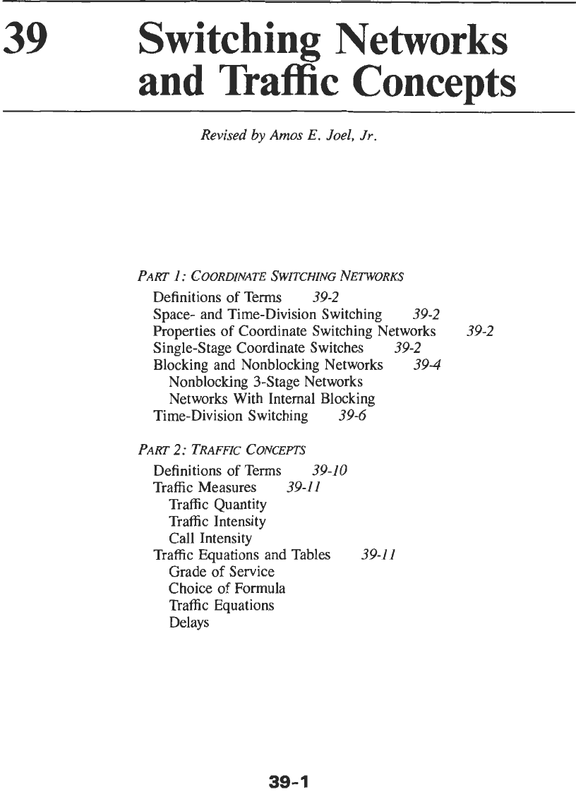
39
Switching Networks
and
Traffic
Concepts
Revised
by
Amos
E.
Joel, Jr.
PART
1:
COORDINATE SWITCHING
NETWORKS
Definitions
of
Terms
39-2
Space- and Time-Division Switching
39-2
Properties
of
Coordinate Switching Networks
Single-Stage Coordinate Switches
39-2
Blocking and Nonblocking Networks
394
39-2
Nonblocking 3-Stage Networks
Networks With Internal Blocking
Time-Division Switching
39-6
PART
2:
TRAFFIC
CONCEPrS
Definitions
of
Terms
39-10
Traffic Measures
39-1
I
Traffic Quantity
Traffic Intensity
Call Intensity
Grade
of
Service
Choice
of
Formula
Traffic Equations
Delays
Traffic Equations and Tables
39-11
39-
1