Mench M.M. Fuel Cell Engines
Подождите немного. Документ загружается.


c05 JWPR067-Mench January 23, 2008 18:58 Char Count=
230 Transport in Fuel Cell Systems
Table 5.11 Henry’s Law Constants (atm · cm
3
/mol) as a Function of Temperature for Gases into
Water
Species 290 K 300 K 310 K 320 K 330 K 340 K
CO
2
66 94 119 149 176 —
O
2
2079 2462 2845 3119 3338 3557
H
2
3666 3940 4104 4159 4213 4159
CO 2791 3283 3666 4049 4378 4596
Air 3393 4049 4596 5034 5417 5691
N
2
4159 4870 5527 6019 6457 6785
Source: Data adapted from [29].
Notice that the oxygen constant increases with temperature, which means the oxygen
concentration in the liquid decreases with temperature. This is why the water temperature in
a fishbowl is so critical. If the water temperature is too high, too little oxygen concentration
is available for the fish and they will suffocate. The oxygen into water can be curve-fit using
thedatafromTable5.11as
H
O
2
−water
atm · cm
3
mol
= exp
−1048
T
+ 11.29
(5.65)
For PEFC electrolyte the oxygen and hydrogen flux is very important in the membrane.
Henry’s constant (in slightly different units, so that the solid-phase concentration and not
the mole fraction is known) has been correlated [30]:
H
O
2
−Nafion
atm · cm
3
mol
= exp
−666.0
T
+ 14.1
(5.66)
For hydrogen into Nafion, Henry’s constant is relatively constant in temperature, as mea-
sured for Nafion 120 polymer at 25
◦
C[30]:
H
H
2
−Nafion
(atm · cm
3
/mol) = 4.5 × 10
4
(5.67)
Once the reactant is across the phase boundary, it diffuses in the new phase toward the
catalyst.
Example 5.11 Crossover through Solid Electrolyte Calculate the molar flow rate of
hydrogen crossover into and through a 51-µm-thick Nafion electrolyte. The anode is op-
erating at 353 K and 1 atm pressure with a mole fraction of 0.6 hydrogen. Determine the
mass transfer limiting hydrogen crossover current density from this value.
SOLUTION First you can solve for the concentration at the anode side in the Nafion:
C
H
2
/membrane side
mol
cm
3
=
y
i,gas side
P
gas side
H(T )
=
0.6 × 1
4.5 × 10
4
mol
cm
3
= 1.33 × 10
−5
mol/cm
3

c05 JWPR067-Mench January 23, 2008 18:58 Char Count=
5.3 Gas-Phase Mass Transport 231
Now this concentration must diffuse toward the cathode, which, presumably, has zero
concentration of hydrogen. From Fick’s law and Eq. (5.61) at 353 K
˙
n
H
2
=−D
H
2
−Nafion
∂C
∂x
= 4.1 × 10
−3
exp
−2602
T
·
1.33 × 10
−5
51 × 10
−4
mol
cm
2
· s
= 6.74 × 10
9
mol/cm
2
· s
As discussed in Chapter 4, fuel crossover is typically measured as an effective crossover
current density. The mass transfer limiting hydrogen crossover current density is the maxi-
mum current density that could be achieved if all of the hydrogen crossover were used as
fuel. This corresponds to a limiting current density of
˙
n
H
2
=
iA
nF
= 6.74 × 10
9
mol/s ⇒ (6.74 × 10
9
)nF = i
limiting
= 1.31 mA/cm
2
COMMENTS: Typical PEFCs have a range of about 1–10 mA/cm
2
hydrogen crossover.
Also, there is some additional resistance from the ionomer in the catalyst layers which
was not accounted for here. We could account for this by assuming an equivalent ionomer
thickness in the catalyst layer based on the ionomer content.
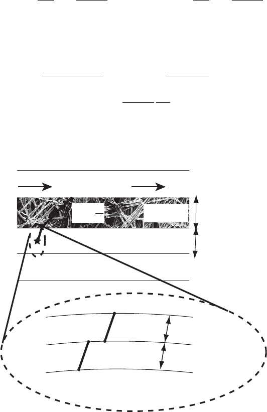
Example 5.12 Mass Transfer Limiting Current Density with Film Resistances for PEFC
In Example 5.8, we solved for the mass transport limiting current density of an electrode
based on the resistance to gas-phase transport only. In the PEFC and some other fuel cells,
a thin layer of liquid or ionomer may cover portions of the catalyst surface, resulting in an
additional film resistance. Symbolically show this situation to form a more precise model of
mass transfer limited current density at an electrode. Ignore convective effects and Knudsen
diffusion in this problem.
SOLUTION The film resistance acts in series with the resistance in the diffusion media
and catalyst layer. We can start by showing the resistance flow through the diffusion media,
into the catalyst layer in the gas phase, and into an ionomer and liquid films:
i
l
=−nFD
eff,DM
C
∞
− C
DM
+
δ
DM
=−nFD
eff,CL
C
DM
+
− C
DM
−
δ
CL
=−nFD
R,water
C
H
2
O
+
− C
H
2
O
−
δ
w
=−nFD
R,NF
C
NF
+
− C
s
δ
NF
which represents four equations and eight unknowns: C
∞
, C
DM
+
, C
DM
−
, C
H
2
O
+
, C
H
2
O
−
,
C
NF
+
, C
s
, and i
l
. One of the remaining necessary four equations comes from the ideal gas
law:
C
∞
=
y
i
P
R
u
T
Another unknown is eliminated under limiting conditions as C
s
goes to zero at i = i
l
.
Another two come from Henry’s law, to step across the gas–liquid phase boundary and the
gas–Nafion phase boundary:
C
i,liquid/membrane side
mol
cm
3
=
y
i,gas side
P
gas side
H(T )
c05 JWPR067-Mench January 23, 2008 18:58 Char Count=
232 Transport in Fuel Cell Systems
or
C
H
2
O
−
mol
cm
3
=
y
H
2
O
+
P
H
W
(T )
and C
NF
+
mol
cm
3
=
y
H
2
O
+
P
H
NF
(T )
A final equation can be determined by substitution of one of the diffusion equations into
another to substitute for an unknown. Any can be chosen. For example,
−nFD
R,water
C
H
2
O
+
− C
H
2
O
−
δ
w
=−nFD
R,NF
C
NF
+
− C
s
δ
NF
⇒
D
R,water
D
R,NF
δ
NF
δ
w
C
H
2
O
+
− C
H
2
O
−
= C
NF
+
The resulting calculations are very tedious by hand but yield substantially reduced limiting
current density values that are closer to those actually experienced.
Reactant Flow
Electrolyte
Catalyst Layer
Diffusion
Media (DM)
Flow Channel
c
8
?
˙
n
= −
D
∂
C
∂
x
c
8
C
CL
C
H2O
+
C
H2O
-
Water Layer
Ionomer Layer
Catalyst
C
S
= 0
C
NF
δNF
δW
δDM
δCL
COMMENTS: We could also have added the catalyst layer diffusion resistance. This
model, while serving as a useful qualitative tool, is not precise, simply because we have
no idea of the thickness of any layer of liquid water of ionomer locally in the electrode
structures. Also, some local flooding simply turns off the current in this location by these
effects, but this only means areas which are flooding have reduced performance. Other
areas in the fuel cell may not be flooded, so that the net effect of the flooding is actually
to reduce the electrochemically active surface area, which is an approach taken by modely
including flooding, discussed later in this chapter.

c05 JWPR067-Mench January 23, 2008 18:58 Char Count=
5.4 Single-Phase Flow in Channels 233
Table 5.12 Summary of Orders of Magnitude of Diffusion
Coefficients for Various Modes of Transport
Mode of Diffusion Order (cm
2
/s)
Bulk gas in gas O(0.1)
Dissolved gas in liquid O(10
−5
)
Gas into liquid O(10
−4
)
Knudsen O(10
−3
–0) f (pore size)
O
2
/H
2
in Nafion O(10
−6
) at 353 K
Surface diffusion O(10
−5
–10
−7
)
5.3.7 Surface Diffusion
At the catalyst–electrolyte surface we have gas-phase diffusion, and there can also be
additional surface diffusion. In surface diffusion, gas molecules physically or chemically
absorb onto a solid surface. If it is physical absorption, the species are highly mobile. If
it is chemisorption and the molecule is more strongly bonded to the specific site, species
are not directly mobile but can move via a hopping mechanism. Surface diffusion rates can
be measured by direct measurement of the flux of a nonreacting gas across the material
surface. The difference between the measured diffusion and predicted Knudsen diffusion is
calculated to be the surface diffusion component. Values of the surface diffusion coefficient
(D
s
)are∼10
−5
cm
2
/s in solids and liquids, but these vary widely since surface interaction
is involved. Also, D
s
is a strong function of temperature and surface concentration. Surface
diffusion adds to the overall diffusion but is typically less than one-half of the Knudsen
component and so has been mostly neglected in fuel cell analysis.
5.3.8 Diffusion Summary
To help summarize the concepts covered on diffusion transport, Table 5.12 is provided.
Tortuosity and porosity further modify the gas–gas diffusivities if flow is through a porous
media. Pressure, temperature, and other parametric dependencies vary between the modes.
5.4 SINGLE-PHASE FLOW IN CHANNELS
It is the goal of reactant flow manifold and channel design in PEFCs to provide excellent
access to the catalyst while suffering the lowest possible pressure drop. Since parasitic
blowers or fans typically must power air and possibly fuel through the fuel cell, the pressure
loss is directly related to the power output of the fuel cell. For some higher pressure systems,
the power consumed by pumps and blowers can reach 30% of the power generated by the
fuel cell.
5.4.1 Pressure Drop
One of the most important aspects of fuel cell design is the reactant flow through the
manifolds and flow field, because parasitic losses from driving the flow through the cell can
c05 JWPR067-Mench January 23, 2008 18:58 Char Count=
234 Transport in Fuel Cell Systems
Electrolyte
Catalyst layer
Diffusion media
Flow channel
Consumption flow
to catalyst layer
Product flow uptake
Frictional pressure drop
∆P
Slug
blockage
Droplet
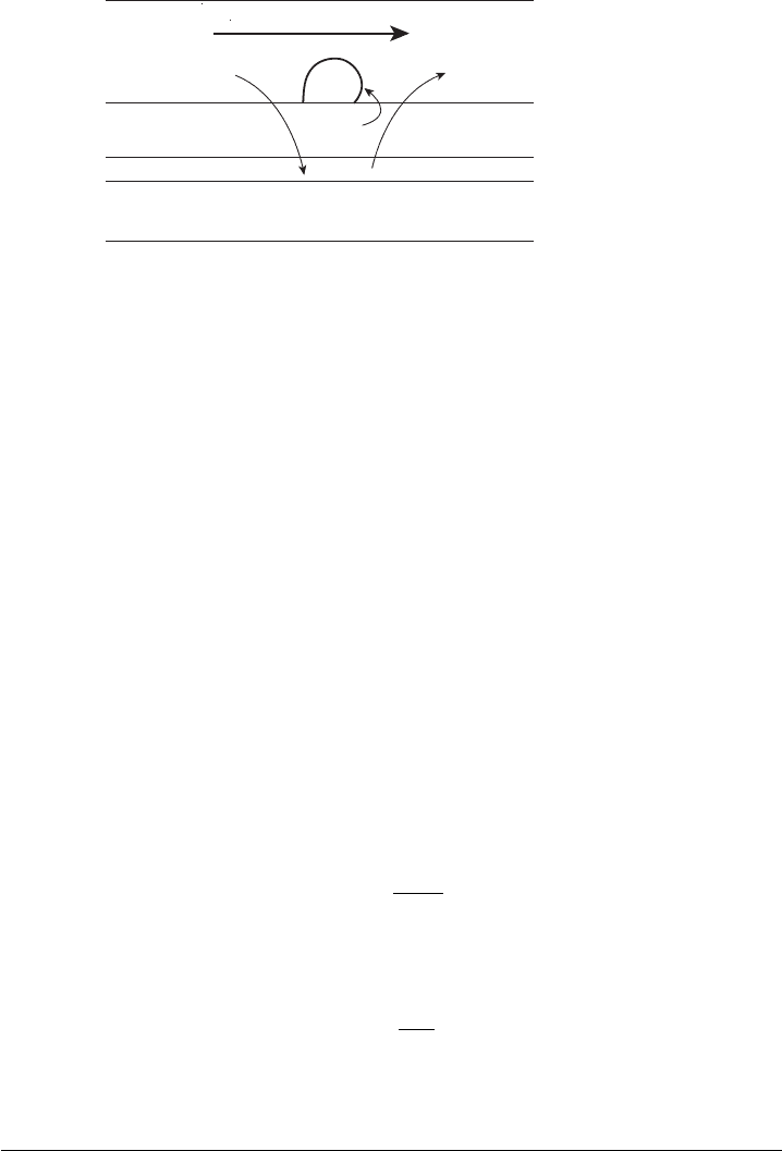
Figure 5.17 Schematic of pressure drop and mass exchange in the flow channel of fuel cell.
be the dominant. The pressure change in flow channels is a result of several phenomena, as
illustrated in Figure 5.17:
1. Frictional Losses This is the most easily recognized source of pressure loss in the
flow channel. In all channels, the viscous losses retard the flow so that a pressure
drop per length of the channel is required to maintain a given flow rate. In the limit
of high stoichiometry, this loss dominates pressure drop.
2. Consumption of Reactant The consumption of reactant reduces the pressure in the
fuel cell flow channel. In the limit, with neat hydrogen and a high fuel utilization,
the flow at the exit can be near a vacuum state.
3. Production of Species Product species are added to the flow in the channel. Water
vapor generated by reaction will enter the vapor state until the saturation limit.
4. Two-Phase Flow or Blockages In low-temperature PEFCs, liquid water droplets
can accumulate in a sporadic and nonuniform fashion and block flow channels,
increasing pressure drop. In all fuel cells, partial channel blockage from materials
in the flow channel (e.g., in PEFCs, the gas diffusion media can sometimes sag into
the channel) will result in increased pressure drop.
Frictional Losses The basic dimensionless parameter representing the ratio of momentum
to vicious losses is the Reynolds number Re:
5
Re =
ρVd
h
µ
(5.68)
where V is the velocity, ρ is the fluid density, µ is the fluid viscosity, and d
h
is the hydraulic
diameter, defined as
d
h
=
4A
x
P
w
(5.69)
where A
x
is the cross-sectional area of flow and P
w
is the length of the perimeter wet by
flow. For round channels, this reduces to simply the channel diameter, where for rectangular
5
In this text, it is assumed the reader has a basic background in fluid mechanics. The reader is referred to
undergraduate texts in fluid mechanics, such as F. M. White, Fluid Mechanics, 5th ed., McGraw Hill, New York,
2003.
c05 JWPR067-Mench January 23, 2008 18:58 Char Count=
5.4 Single-Phase Flow in Channels 235
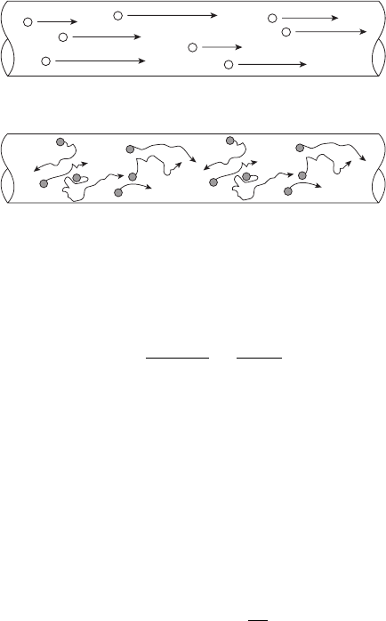
(a)
(b)
Figure 5.18 Illustration of individual particle flow trajectories in (a) laminar and (b) turbulent flow.
channels [2] of width w and height h
d
h
=
4wh
2w + 2h
=
2wh
w + h
(5.70)
For Re < 3000 in an internal channel, the flow is typically laminar, a condition characterized
by uniform streamlines and locally steady flow. For an internal channel with Re > 3000,
the flow transitions to turbulent flow, characterized by local velocity profile fluctuations
and enhanced mixing, as illustrated in Figure 5.18. The flow in a vast majority of fuel cells
is highly laminar, which greatly simplifies many important calculations.
Physically, the cause of the pressure drop for internal flow is the viscous interaction
with the wall, where there is a no-slip condition (V
wall
= V
fluid
). The one-dimensional shear
force at the wall for a Newtonian fluid is proportional to the fluid strain and is related to
fluid viscosity:
F
wall
= τ A = Aµ
du
dy
(5.71)
where A is the surface area of contact between the fluid and the wall and du/dy is the slope
of the change in velocity with distance from the wall. To overcome the shear restraining
force imposed by the channel walls and the viscous nature of the fluid, the flow will
experience a pressure drop along the channel.
In open-field flow, such as in the atmosphere, there are no restraining walls or objects
that impose the no-slip condition. When flow from an open channel or flow manifold
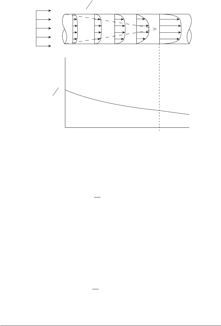
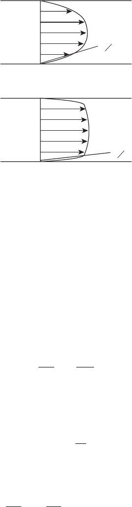
enters a channel, the flow field develops along an entry length. The internal flow profile for
developing flow is shown in Figure 5.19. At first, the flow entering the confined channel is
undeveloped, and the flow profile still varies along the axial direction. Because of the no-slip
condition, the particles at the wall must have the same velocity as the wall, which sets up a
very steep du/dy profile within the developing boundary layer. Hence, in this developing
entrance region, the pressure drop per unit length is higher than in the developed section
of the channel. Further on down the channel, the boundary layers grow and eventually
converge until the flow profile no longer changes in the axial direction. The distance from
the entrance of the channel to the point where the internal flow profile becomes independent
of the axial location is termed the entrance length (L
e
) and is characterized by a higher
c05 JWPR067-Mench January 23, 2008 18:58 Char Count=
236 Transport in Fuel Cell Systems
0
?
du
dy
at wall is very steep
l
e
∆
P
x
x
from manifold
V
∞
Figure 5.19 Developing flow profile in a channel. The shear forces that accumulate along the wall
result in a pressure drop along the channel that must be provided for by the reactant flow system.
pressure drop and mixing per unit length compared to the fully developed portion of the
channel. The entrance length for laminar internal flow can be estimated from
L
e
d
h
≈ 0.06 Re (5.72)
With a critical Reynolds number for transition to turbulence around 3000,
6
the max-
imum length of developing flow is about 180 diameters. A typical fuel cell flow channel
hydraulic diameter is around 1 mm, which means the flow will be developing (and expe-
riencing greater pressure loss and enhanced mixing) for up to 18 cm of the flow channel
length. When the flow experiences a sudden turn, or switchback, recirculation zones and
additional development length after the turn occur. As a result of entrance and flow field
effects, the actual frictional pressure drop in a fuel cell flow channel is typically greater
than predicted by fully developed flow theory.
For turbulent flow, the following relationship for entrance length is used:
L
e
d
h
≈ 4.4Re
1/6
(5.73)
The entrance length for turbulent flow can be technically infinite if Re is infinite but is
typically less than that for laminar flow because of the enhanced mixing. Additionally,
6
Many authors refer to the critical Reynolds number (Re
crit
) as 2300. The transition from laminar to turbulent
profiles can actually occur over a relatively broad range and is a function of the channel geometry and surface
roughness. In this text, Re
crit
= 3000 is used as a general guideline.
c05 JWPR067-Mench January 23, 2008 18:58 Char Count=
5.4 Single-Phase Flow in Channels 237
(a)
du
dy
(b)
du
dy
Figure 5.20 Laminar and turbulent profile boundaries: (a) fully developed laminar profile; (b) fully
developed turbulent profile. Notice the turbulent du/dy profile is much steeper, leading to a higher
pressure drop per unit length via Eq. (5.71).
the initial and fully developed flow profiles are more similar (see Figure 5.20). For a very
turbulent Reynolds number of 1,000,000, the entrance length is still only 44 hydraulic
diameters. While this may suggest that reduced pressure drop could be obtained in fuel
cells if the flow was turbulent, the overall pressure drop (and parasitic losses required to
obtain turbulent flow velocity) is far greater for turbulent flow due to the higher du/dy
profile at the wall for a turbulent-flow profile.
From a force balance on the internal flow surface and conservation of energy, we can
derive the following equation relating frictional pressure drop per unit length in a closed
channel for fully developed flow:
P
L
= f
ρV
2
2d
h
(5.74)
where f is the Darcy friction factor. As discussed, the velocity V is not constant in a fuel
cell due to consumption and other factors and is a function of location along the channel.
For laminar flow, f can be determined from flow theory [2]:
f
lam
=
64
Re
(5.75)
Therefore, for laminar flow, the pressure drop is proportional to the velocity. For laminar,
fully developed flow, the pressure drop can be modeled as Hagen–Pouiseville flow:
P
L
= 32
µV
d
2
h
(laminar flow) (5.76)
where V is the velocity and P is the pressure drop through the pore. For turbulent flow,
much experimental data have been correlated, and the following equation by Colebrook
c05 JWPR067-Mench January 23, 2008 18:58 Char Count=
238 Transport in Fuel Cell Systems
[31] is the most commonly applied:
1
f
turb
=−2.0log
ε/d
h
3.7
+
2.51
Re f
1/2
turb
(5.77)
This implicit equation for f can be easily solved computationally but is rarely needed in
fuel cells since the flow is typically laminar in nature. Here ε is the wall roughness height,
which is a function of the surface of the channel walls.
For advanced modeling purposes, the addition of minor loss, flow field switchback,
and manifolding effects can be approached analytically. In practice, however, the actual
pressure drop in an cell or stack is very difficult to predict with high precision due to
the effects of entry length, local turbulence, additional minor losses from switchback,
consumption, uptake and other effects. Additionally, in PEFCs and AFCs with a porous
diffusion media, there can be unintentional convective flow under the channels, which
reduces overall pressure drop, as discussed in Chapter 6. Therefore, a good starting point is
to assume the frictional pressure drop dominates (which has been found to be true in certain
PEFCs [32]) and calculate an expected loss from Eq. (5.76). For a particular fuel cell, the
pressure drop can be correlated as a function of entrance velocity, since this is relatively
easy experimental data to obtain.
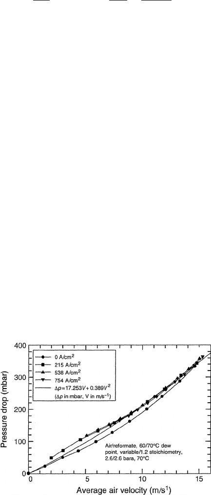
An example is shown in Figure 5.21 where the general linearity indicates pressure
drop is dominated by laminar frictional losses. For the particular stack in Figure 5.21
(and in fact many stacks), the pressure drop can be correlated as a polynomial function of
velocity, which globally accounts for the laminar (V dependence) and turbulent/minor loss
dependency (∼V
2
dependence):
P = aV + bV
2
(5.78)
where a and b are empirically derived constants for a particular fuel cell and are by no
means uniform for different cell, manifold, stack designs, or operating conditions.
Consumption of Reactant Due to consumption, the uptake of product or moisture, the
molar flow rate (and velocity) of the reactant mixture in the channel is not a constant and
Figure 5.21 Measured and correlated pressure drop in a Ballard fuel cell as a function of velocity.
(From Ref. [32] with permission.)

c05 JWPR067-Mench January 23, 2008 18:58 Char Count=
5.5 Multiphase Mass Transport in Channels and Porous Media 239
varies with location along the channel length. At the inlet, we can show that
˙
n
mix
(
inlet
)
= QA =
λ
y
i
I
nF
(5.79)
where Q is the volume flow rate, y
i
is the mole fraction of the reacting species, and I is
the current. For a constant current across the electrode surface, we can show that along the
flow path the initial reactant gas is reduced by consumption:
˙
n
mix
(x) =
I
nF
λ
y
i
−
x
L
(5.80)
where x is the length along the channel and L is the total length of the channel. Consumption
or uptake of species into the flow results in a changing flow velocity, but the pressure is
always highest at the input and decreases along the flow channel. Along the channel, with
a net uptake of mass considered (e.g., water vapor uptake), conservation of mass yields
˙
n
mix
(x) =
iA
nF
λ
y
i
−
x
L
+
˙
n
uptake
(x) (5.81)
where
˙
n
uptake
water vapor and other gas-phase species production combined and the current
density is assumed to be uniform across the fuel cell surface. At the exit of the fuel cell
under the same assumptions, we can show that
˙
n
mix,out
=
˙
n
mix,in
−
˙
n
consumed
+
˙
n
uptake
=
λ
y
i
iA
nF
−
iA
nF
=
iA
nF
λ
y
i
− 1
+
˙
n
uptake
(5.82)
The fuel cell polarization model developed in Chapter 4 can be extended to multiple
dimensions, and the current density distribution can also be modeled based on concepts
in this book. In the limit of high stoichiometry, Eq. (5.81) becomes invariant in x, and the
reactant concentration is constant in the flow channel. At low stoichiometry, however, the
reactant concentration decreases throughout the channel length and can result in greatly
decreased current density at the exit locations [33]. In general, almost nothing in a fuel cell
is actually homogeneous. The current, temperature, and species vary throughout the fuel
cell in all directions for almost every fuel cell design. In many cases, the variation in many
parameters such as temperature can be used to an advantage and is a critical component in
design optimization.
5.5 MULTIPHASE MASS TRANSPORT IN CHANNELS
AND POROUS MEDIA
7
5.5.1 Multiphase Flow in Gas Channels
Mixed liquid/gas-phase flow can occur in direct alcohol and hydrogen polymer electrolyte
fuel cells. For the hydrogen fuel cell, liquid water can build up in either the anode or
7
This section may be omitted without loss of continuity providing detailed analysis of PEFC flooding covered in
Chapter 6 is also omitted.