Massoud M. Engineering Thermofluids: Thermodynamics, Fluid Mechanics, and Heat Transfer
Подождите немного. Документ загружается.


822 VId. Applications: Simulation of Thermofluid Systems
The set of nine equations may be reduced to six by substitution from the continu-
ity equations into the energy equations. The resulting set at every time step is
found as:
»
»
»
»
»
»
»
»
»
»
»
¼
º
«
«
«
«
«
«
«
«
«
«
«
¬
ª
−−
∂
∂
−
∂
∂
∂
∂
−
∂
∂
∂
∂
∂
∂
∂
∂
∂
∂
∂
∂
∂
∂
∂
∂
∂
∂
−
−
111000
00
v
0
vv
0
v
0
vv
0
vv
00V0
00V00
3
3
2
2
3
3
2
2
3
3
3
1
1
1
3
3
3
1
1
1
2
2
2
1
1
1
2
2
2
1
1
1
232
11
P
T
P
T
h
T
h
T
P
m
P
m
h
m
h
m
P
m
P
m
h
m
h
m
cmm
cm
¸
¸
¸
¸
¸
¸
¸
¸
¸
¹
·
¨
¨
¨
¨
¨
¨
¨
¨
¨
©
§
3
2
1
3
2
1
P
P
P
h
h
h
=
¸
¸
¸
¸
¸
¸
¸
¸
¹
·
¨
¨
¨
¨
¨
¨
¨
¨
©
§
−−
−−
−−
−
0
0
vv
vv
3311
2211
33222
111
αα
αα
ααβ
αβ
hh
h
VId.6.8
Equation VId.6.8 can be solved by Gaussian elimination. Having initial volumes,
masses, enthalpies, physical properties and their derivatives, we can find enthalpy
and pressure derivatives by solving the above set. The mass, enthalpy, pressure
and volume derivatives are then integrated over a time step to find pressures,
masses, volumes and enthalpies in a subsequent time step:
1NN
kkk
mm t
α
+
=+∆
1NN
kkk
hhht
+
=+∆
1NN
kkk
PPPt
+
== + ∆
1
VVV
NN
kkk
t
+
=+∆
This process is repeated until the end of the specified transient is reached.
In addition to the constitutive equations required to represent many of the proc-
esses as discussed in Section 5, we use three equations of states for water, steam,
and gas to obtain
),(v
,1 kkkk
hPf= ,
),(
,2 kkkk
hPfT = ,

6. Mathematical Model for PWR Components, Containment 823
),(/v
,3 kkkkk
hPfh =
∂∂
,
),(/v
,3 kkkkk
hPfP =
∂∂
,
),(/
,5 kkikk
hPfhT =
∂∂
, and
),(/
,65 kkkkk
hPfPT =
∂∂
,
where index k = 1, 2, and 3. Derivative of properties of the gas in the bulk vapor
region, treated as an ideal gas, is readily obtained as:
33,
3
3
3
v
Pc
R
h
p
=
∂
∂
,
3
3
3
3
vv
PP
−=
∂
∂
,
3,3
3
1
p
ch
T
=
∂
∂
, and
0
3
3
=
∂
∂
P
T
.
Recall that properties of saturated water and saturated steam are functions of either
pressure or temperature. However, properties of subcooled water and superheated
steam are functions of two variables. Thermal hydraulic computer codes use
curve fits to the steam tables. However, to simplify analysis in the following ex-
ample, we are assuming that superheated steam can be treated as an ideal gas.
This assumption is reasonable, especially for specific volume (v = RT/P) at low
pressures and high temperatures. This assumption is less accurate for enthalpy of
the superheated steam, dh = c
p
dT, if c
p
is treated as a constant.
Example VId.6.1. A heavy load drop inside a containment ruptures two pipes.
One carrying superheated steam and the other compressed air. Estimate the con-
tainment response for the first 10 minutes to this event. Treat steam and air as
ideal gases. Data: V
containment
= 2E6 ft
3
(56.6 m
3
), P
o
= 14.7 psia (101.3 kPa), T
o
=
120 F (49 C),
φ
o
= 59%,
steam
m
= 100 lbm/s (45.36 kg/s), h
steam
= 1200 Btu/lbm
(2791 kJ/kg),
air
m
= 50 lbm/s (22.68 kg/s), T
air
= 350 F (177 F). Ignore all safety
systems and steam condensation.
Solution: We calculate the initial masses, pressures, volumes, and enthalpies.
Since no pool region is specified, hence, V
1
= 0, and V
2
= V
3
= 2E6 ft
3
(56.6 m
3
)
P
2
= 0.59 × P
sat
(120 F) = 1 psia (6.9 kPa), P
3
= 14.7 – 1 = 13.7 psia (0.094 kPa)
and P
1
= 14.7 psia (101.3 kPa)
h
2
= h
100
+ c
p,2
(T – 100) = 1105.3 + 0.445(120 – 100) = 1114 Btu/lbm (2591 kJ/kg)
h
3
= 0.24(120 +460) = 139.2 Btu/lbm (323.7 kJ/kg)
v
2
= R
2
T
2
/P
2
= 345.7 ft
3
/lbm (21.58 m
3
/kg). Thus, m
2
= V/v
2
= 1.0E6/345.7 =
5785 lbm (2624 kg)
v
3
= R
3
T
3
/P
3
= 15.68 ft
3
/lbm (0.978 m
3
/kg). Thus, m
3
= V/v
3
= 1.0E6/15.68 =
1.275E5 lbm (0.578E5 kg).
Since we have only the vapor region, Equation VId.6.8 simplifies to:

824 VId. Applications: Simulation of Thermofluid Systems
¸
¸
¸
¸
¸
¹
·
¨
¨
¨
¨
¨
©
§
+−
−
−
=
¸
¸
¸
¸
¸
¹
·
¨
¨
¨
¨
¨
©
§
¸
¸
¸
¸
¸
¸
¸
¹
·
¨
¨
¨
¨
¨
¨
¨
©
§
∂
∂
−
∂
∂
∂
∂
−
∂
∂
∂
∂
−
∂
∂
∂
∂
−
∂
∂
−
−
0
vv
v
v
v
v
V00
0V0
3322
333
222
3
2
3
2
2
3
2
2
3
3
2
2
3
3
3
2
2
2
3
3
3
2
2
2
33
22
αα
αβ
αβ
h
h
P
P
h
h
P
T
P
T
h
T
h
T
P
m
P
m
h
m
h
m
cm
cm
Next, we find the forcing functions:
α
1
= 0 lbm/s,
α
2
= 100 lbm/s, and
α
3
= 50 lbm/s
β
2
= 100 × 1200 = 1.2E5 Btu/s, and
β
3
= 50 × 0.24(350 + 460) = 0.972E4 Btu/s
We now develop derivatives of specific volumes and temperatures:
∂v
2
/∂h
2
= R
2
/c
p,2
P
2
= (1545/18)/(0.445 × 144P
2
) = 1.339/P
2
∂v
3
/∂h
3
= 1.543/P
3
∂v
2
/∂P
2
= –v
2
/P
2
= –345.7/P
2
= –2.4 ft
5
/lbm·lbf
∂v
3
/∂P
3
= –v
3
/P
3
= –15.68/P
3
= 7.97E-3 ft
5
/lbm·lbf
∂T
2
/∂h
2
= 1/c
p,2
= 2.247 lbm·F/Btu
∂T
3
/∂h
3
= 1/c
p,3
= 4.167 lbm·F/Btu
Upon substitution, the set of equations for the first time step becomes:
¸
¸
¸
¸
¸
¹
·
¨
¨
¨
¨
¨
©
§
−
=
¸
¸
¸
¸
¸
¹
·
¨
¨
¨
¨
¨
©
§
¸
¸
¸
¸
¸
¹
·
¨
¨
¨
¨
¨
©
§
−
−−
−
−
0
33786
2760
8600
00167.4247.2
4.101313888143607746
5E7.305.275E10
05E7.305785
3
2
3
2
P
P
h
h
we find the four unknowns as
2
h
= 1300 Btu/lbm s,
3
h
= 70 Btu/lbm s,
2
P
=
20.3 psi/s and
3
P
= 24.1 psi/s. Having the derivatives, we find h
2
, h
3
, P
2
, and P
3
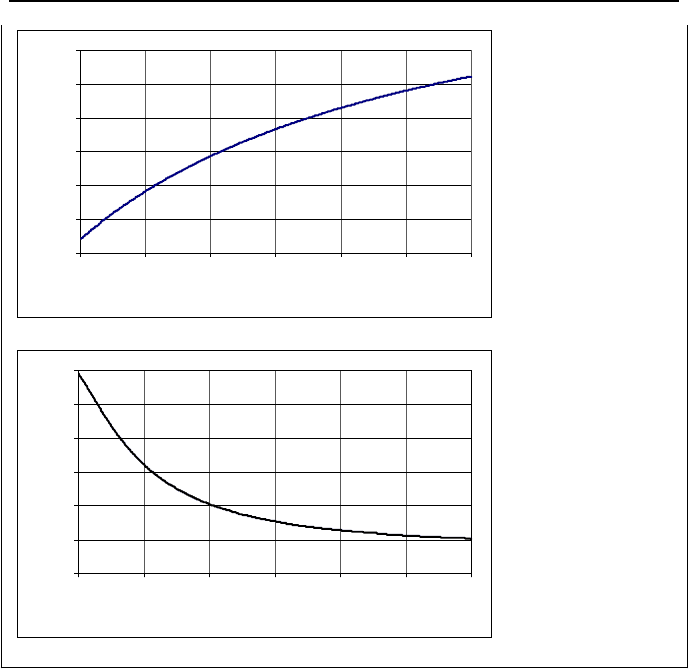
at the next time step. The FORTRAN program to solve this problem is included
on the accompanying CD-ROM. The results for this problem for temperature and
relative humidity are shown in the plots. Containment pressure in 10 minutes
reaches 40 psia (2.76 bar).
6. Mathematical Model for PWR Components, Containment 825
100
150
200
250
300
350
400
0 100 200 300 400 500 600
Time (s)
Temperature (F)
0
0.1
0.2
0.3
0.4
0.5
0.6
0 100 200 300 400 500 600
Time (s)
Relative Humidi
t
6.1. Break Flow Split
Consider the containment of Figure VId.6.1(b) initially being at P
o
and T
o
. We
now inject saturated water or a two-phase mixture to the vapor region of this con-
tainment. The pressure and temperature of the injected flow are greater than those
of the containment, P
m
> P
o
and T
m
> T
o
, where subscript m stand for mixture.
Our goal is to find the percentage of the injected flow that becomes steam and
joins the vapor region and the portion that becomes water and flows to the pool
region. Such injected flow split depends on the conditions at the plane of entrance
to the containment. If the injected flow to the vapor region is saturated water for
example, the flow partially flashes to steam upon entering the low pressure vapor
region. The constitutive equations for determination of the injected flow split into
two distinct phases in the containment are known as the pressure flash and the
temperature flash models. Both models assume an isoenthalpic split of the in-
jected flow so that:
826 VId. Applications: Simulation of Thermofluid Systems
ggffmm
hmhmhm
+= VId.6.8
However, the difference between the two models lies in the evaluation of the satu-
rated water and saturated steam enthalpies. To elaborate, let’s define the fraction
of the flow which flashes to steam, Ȥ as:
)()(
)(
12
1
yhyh
yhh
fg
fm
−
−
=
χ
VId.6.9
In the pressure flash model, the saturation enthalpies are developed based on pres-
sure. For example, y
1
= y
2
= P
2
(i.e. the partial pressure of steam). Another way
to calculate the split fraction is to take y
1
= P
1
(i.e. total pressure in the contain-
ment) and y
2
= P
2
or to take y
1
= y
2
= T
2
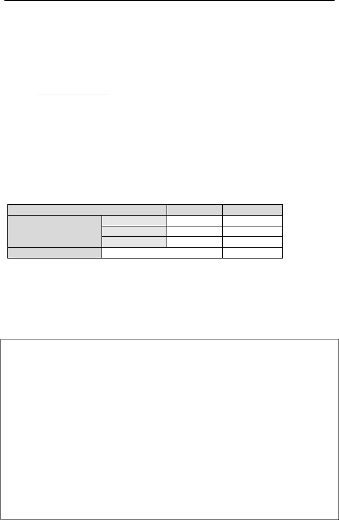
, as summarized in Table VId.6.1.
Table VId.6.1. Summary of various break flow split models
Break Flow Split y
1
y
2
Model A P
1
P
1
Model B P
1
P
2
Pressure Flash
Model C P
2
P
2
Temperature Flash T T
Note that in some references the temperature flash model is defined differently.
In the temperature flash model described by Hargroves for example, the injected
flow is instantaneously mixed and reaches equilibrium with the steam in the vapor
region.
Example VId.6.2. A high energy pipe break occurs inside containment. Com-
pare the split fraction of the break flow using various models of Table VId.6.1.
Data: P
o
= 16.5 psia, T
o
= 125 F,
φ
o
= 51.5%, h
m
= 550 Btu/lbm.
Solution: We find P
2
= 0.515 × P
sat
(125 F) = 1 psia. Thus,
P
3
= P
1
– P
2
= 16.5 – 1 = 15.5 psia.
(a) y
1
= y
2
= 16.5 psia;
Ȥ
a
= (550 – 186.11)/(1152.7 – 186.11) = 0.376 steam and 62.4% water
(b) y
1
= 16.5 psia and y
2
= 1 psia;
Ȥ
b
= (550 – 186.11)/(1105.8 – 186.11) = 0.395 steam and 60.5% water
(c) y
1
= y
2
= 1 psia;
Ȥ
c
= (550 – 69.730)/(1105.8 – 69.730) = 0.463 steam and 53.7% water
(d) y
1
= y
2
= 125 F;
Ȥ
d
= (550 – 92.960)/(1115.7 – 92.960) = 0.447 steam and 55.3% water

7. Mathematical Model for PWR Components, Steam Generator 827
7. Mathematical Model for PWR Components, Steam Generator
The function of a PWR U-tube steam generator is described in Chapter I. Feed-
water entering the downcomer, Figure I.6.6(b) and mixing with the saturated water
returning from the separator assembly enters the tube bundle to reach saturation
and begins to boil. Heat is transferred from the primary side through the tubes to
the two-phase flow, which further increases steam quality. The two-phase flow
eventually enters the risers or stand pipes of the moisture separator. The saturated
water flows downward to mix with the feedwater while saturated steam enters the
dryer and eventually the steam line.
The primary side response was discussed in Section 3. We now discuss
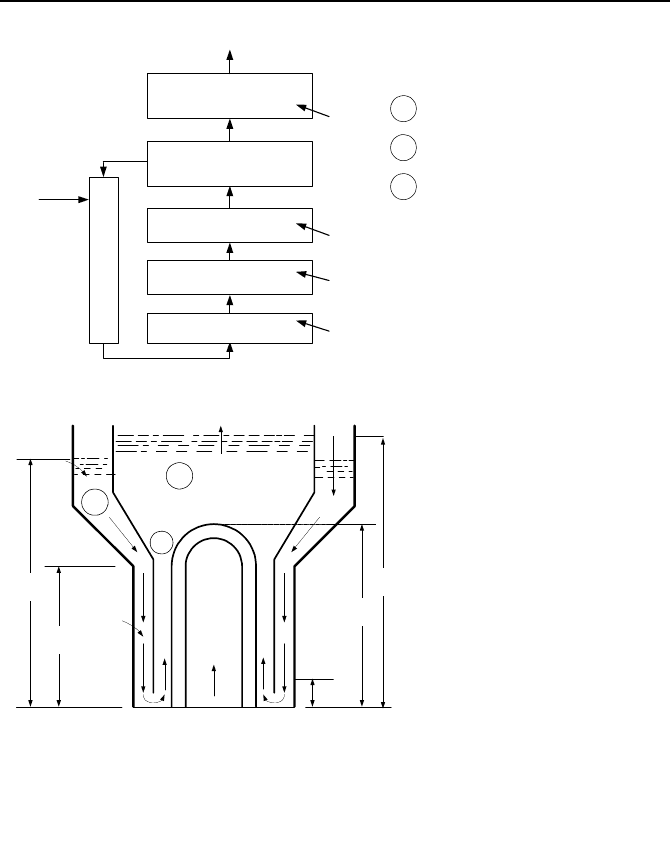
mathematical modeling of the secondary side. Figure VId.7.1(a) shows a simple
nodalization of the secondary side of the steam generator. We may use this simple
nodalization to estimate the mass, enthalpy, pressure, and velocity distribution,
which is helpful in refining the nodalization. Like before, we may also apply the
simplifying assumption of an integral, loop-wide momentum equation as dis-
cussed in Section 3. However, the loop in the case of the secondary side of a
steam generator consists of the following flow path; steam generator downcomer,
tube bundle, riser, separator, dryer. The flow path then leads to the steam dome
and the steam line for the dry saturated steam and back to the downcomer for the
saturated recirculation water, as shown in Figure VId.7.1(b).
The one dimensional integral momentum equation for the flow loop in the sec-
ondary side of the SG is found by applying Equation VId.3.15 to the various re-
gions shown in Figure VId.7.1(b).
Determination of the Boil Off Rate
To obtain a simple relation for estimation of the boil-off flow rate, we consider a
pot-boiler (no circulation) where heat is added to the water region, steam exits the
water region and enters the steam region, and feedwater is added to the water re-
gion to maintain inventory. The mass flow rate of steam is given by Equa-
tion IIa.5.3:
()
cegggggg
AVAVm
αρρ
==
VId.7.1
where
α
e
is the void fraction at the froth level (the interface between the water and
the steam region) and A
c
is the boiler cross sectional area at the froth level, per-
pendicular to the flow direction. Also in Equation VId.7.1,
ρ
g
and V
g
are steam
saturation density and steam velocity, respectively. Since
ρ
g
is a function of the
operating pressure of the boiler (a known quantity) and A
c
is the boiler flow area,
also a known quantity, we need to find relations for
α
e
and V
g
in terms of other
known quantities. Void fraction is given by Equation IIId.2.2:
)/()]1)(/([
boilcgjgefgeo
e
e
mAVXXC
X
ρρρ
α
+−+
=
828 VId. Applications: Simulation of Thermofluid Systems
Steam Dome
R
m
Downcomer
Feedwater
FW
m
f
m
S
m
g
m
Steam
Tube-bundle
Tube-bundle
Tube-bundle
1
Q
2
Q
3
Q
Separator - Dryer
s
Q
1
Downcomer Region
Tube Bundle Region
2
Riser Region
3
L
T
: Swell Level
L
S
: Subcooling Length
L
TB
: Tube Bundle Length
L
D
: Downcomer Length
(a)
L
D
L
DC
L
S
L
TB
L
T
1
3
2
A
TB
D
TB
A
R
D
R
A
W
D
W
A
DC
D
DC
(b)
Figure VId.7.1. Mass and energy control volumes and flow paths for conservation equa-
tion of momentum
where X
e
may be calculated from X
e
= (h
e
– h
f
)/h
fg
and V
gj
from Equation IIId.2.4.
Finally, we find steam velocity, V
g
from V
g
= J + V
gj
where J may be estimated
from J = (
)2/() Acmm
egFW
ρ
+ . In this relation, subscript FW stands for feed-
water and
ρ
e
is the mixture density. Substituting for a
e
and V
g
in Equa-
tion VId.7.1, we find an implicit second-order algebraic equation for the boil off
mass flow rate.

Questions and Problems 829
QUESTIONS
– An electromagnetic pump is used to circulate fluid around a flow loop. De-
scribe the flow trend if the pump is tripped. Compare it with a pump equipped
with a flywheel.
– What is the role of the buoyancy head in early flow coastdown of a forced cir-
culation loop?
– Thermal center in Equation VId.3.12 is defined based on T
H
. How do you de-
fine it based on T
C
?
– Can a natural circulation loop operate with the thermal center of the heat sink
located slightly below that of the heat source?
– What are the important assumptions made that led to the derivation of Equation
VId.3.16, used to estimate the natural circulation mass flow rate?
– What types of work should be considered in the derivation of the pressurizer
pressure?
– In the derivation of the pressurizer pressure, only the conservation equations of
mass and energy were used. What is the application of the momentum equation
in the pressurizer?
– Consider the mass flow rate due to the condensation of steam on the wall of the
pressurizer. Can we obtain this term from the conservation equations of mass
and energy written for the water and the steam regions?
– Can Equation VIc.6.2 be applied to a three region pressurizer by taking k = 3?
– We used one pressure for the pressurizer, taken in the steam region. What as-
sumption makes it possible to apply this same pressure to the water region?
– Plot the in-surge and the out-surge processes of a pressurizer on a T-s diagram.
PROBLEMS
1. Use the definition of thermal center and show that for the core, having near lin-
ear temperature profile, the thermal center is located at H
core
/2 where H
core
is the
core height.
2. Derive Equation VId.3.13, the thermal center of a U-tube steam generator,
where
λ
SG
is measured from the tube sheet. [Hint: Start with Equation VId.3.12.
Then use the definition of the thermal expansion coefficient to relate density dif-
ference to temperature difference. Find
λ
SG
from:
()
[]
³
()
g
sdgs
HC
L
H
SG
ρρ
ρρ
λ
−
⋅−
=
0
KK
where the numerator is given in Example VId.3.1].
3. The following data are given for a U-tube steam generator. Tube mass flow
rate
=m
70E6 lbm/h, total number of tubes N = 8500, tube outside diameter d
o
=
0.75 in, overall heat transfer coefficient U
o
= 1000 Btu/h ft
2
F, average tube length

830 VId. Applications: Simulation of Thermofluid Systems
L = 60 ft, average tube height l = 28 ft, cold leg temperature T
C
= 500 F, hot leg
temperature T
H
= 570 F, pressure P = 2265 psia. For this steam generator find a)
the hydrostatic head and b) the thermal center.
4. The U-tube steam generator of Problem 3 is located in a PWR loop. Use the
following data to find the loop hydrostatic head (i.e., the difference in the eleva-
tions of the heat source and heat sink thermal centers). Z
SG
= 45 ft and (Z
th
)
core
=
30 ft.
5. A PWR is operating at a steady state condition. We now shutdown the plant
and want to estimate the natural circulation flow rate. Although the reactor power
decays after shutdown, we assume the core power remains steady for the duration
of interest. Find the natural circulation flow rate 48 hours after shutdown. Data:
Nominal reactor power: 3000 MWth, reactor pressure: 2265 psia, T
C
= 550 F, T
H
=
610 F,
ΣR = 0.28 ft
-4
.
6. Show that for large values of l*, given in Equation VIa.5.8, the thermal center
of a U-tube steam generator approaches Z
SG
= (1 +
δ
) l/2.
7. Derive Equation VId.3.14 by integrating the hydrostatic pressure term around a
natural circulation flow loop. In this derivation assume a linear temperature pro-
file over the heat source and apply Equation VId.3.12 for the heat sink. [Hint:
Find the density profile in the core and the related hydrostatic head. Take the
height from the heat source exit to the heat sink inlet as h
H
in which
ρ
H
remains
constant. Take the height from the heat sink exit to the heat source inlet as h
C
in
which
ρ
C
remains constant. Then use h
C
– H
core
/2 = h
H
+ H
core
/2]
8. An experimental flow loop is constructed to study events in a PWR plant. The
core consists of electrically heated rods and the two steam generators are simu-
lated by two shell and tube heat exchangers. The vessel is connected to the heat
exchangers by two hot legs and four cold legs. Water flows from the hot leg in the
tubes while the secondary side water is cooled by a cooling tower. The following
flow resistances are measured for this facility R
V
= 227 ft
-4
, R
HL
= 560 ft
-4
, R
HX
=
369 ft
-4
, R
CL
= 767 ft
-4
. Find the natural circulation flow a) assuming no pump ex-
ists in the loop and b) considering four non-operating pumps on each cold leg,
R
Pump
= 1793 ft
-4
. Other design data are: core thermal power = 178 kW, core inlet
temperature = 38 C, vertical distance between the core and the heat exchanger
thermal centers = 0.75 m, average density = 985 kg/m
3
, average specific heat =
4.18 kJ/kg K, and
β
= 0.37E-3 1/K.
9. Find the hydrostatic pressure in a flow loop operating at 3 MPa with T
C
= 150
C and T
H
= 175 C. In this loop, the distance between the heat source and heat sink
thermal centers is 5 m. [Ans.: 1.6 kPa].
10. Derive the hydrostatic head for a once-through steam generator. Tubes are
oriented vertically. Hot water enters the tubes from the top and leaves from the
bottom. Water boils in the secondary side.
Questions and Problems 831
11. The flow resistance of a flow loop is given as 9.81 m
-4
. The loop flow rate at
steady state condition is 5 m
3
/s. Find the total head loss in the loop. Also find the
pressure drop in the loop. The average loop pressure and temperature are 2.5 MPa
and 95 C, respectively. [Ans.: 12.5 m].
12. Show that the half life of a pump impeller is given by:
()
3
o
2
oo
2/1
V
Ȧ2
R
It
P
P
ρ
η
=
where
η
is the pump efficiency, R is the loop flow resistance, and V
is the volu-
metric flow rate in the loop. Subscript o indicates nominal values.
13. A pump is operating in a flow loop at nominal speed. We now turn off the
pump. Find the time it takes the impeller to reach half of its nominal speed. Data:
Ȧ
o
= 124 s
-1
, I
o
= 2200 slug-ft
2
, V
= 85000 GPM,
η
o
= 0.78, R = 0.076 ft
-4
,
ρ
o
=
38 lbm/ft
3
. [Ans.: 2.7 s].
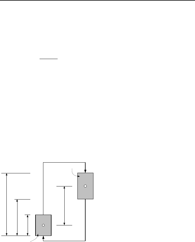
14. A natural circulation loop is shown in the figure. Verify the validity of Equa-
tion VId.3.14. Assume that the thermal centers for the heat source and heat sink,
in this case, are located at the geometrical center of each source. The vertical dis-
tance between the two sources is shown by H
th
. Elevations L
1
, L
2
, and L
3
are
given.
H
th
L
1
L
2
L
3
Heat source
Heat sink
15. Define the system thermal length as the vertical distance between the thermal
centers of the heat source and heat sink, H
th
= (Z
th
)
V
– (Z
th
)
SG
where subscript V
stands for the heat source vessel and SG stands for the steam generator. In this
problem we want to find the effect of the thermal length on the loop flow rate and
the loop temperature gradient. Therefore, we keep changing the loop configura-
tion with respect to the heat sink elevation. Due to height limitation of the build-
ing housing the loop, we would eventually have to place the steam generator hori-
zontally. Assume all design parameters remain the same except for the increasing
thermal length. a) Derive the loop flow rate as a function of the thermal length.