Massoud M. Engineering Thermofluids: Thermodynamics, Fluid Mechanics, and Heat Transfer
Подождите немного. Документ загружается.

682 Vc. Two-Phase Flow and Heat Transfer: Condensation
Solution: For this transient problem, we may estimate the plate temperature, from
an energy balance using the lumped capacitance approach:
()
()
sfilm
s
TThA
dt
Tcd
−=
V
ρ
In this relation, T
film
≈ (T
sat
+ T
s
)/2 and h in Equation Vc.2.6 may be written as:
h =
ζ
(T
sat
– T)
–1/4
where
ζ
=
()
25.0
3
)/()(943.0 Lhkg
ffgfgff
µρρρ
′
−
Assuming
θ
= T
sat
– T
s
, the above energy balance simplifies to:
³³
−= dtcAd )V2/(/
4/3
ρζθθ
Integrating and setting
θ
= 0, we find )V/2/(
4/1
0
cAt
ρζθ
=
θ
0
= (T
sat
– T
s0
) = 212 – 200 = 12 F, A/V = 12/0.125 ft,
ρ
c = 48.8 Btu/ft
3
·F
For the condensate layer, we find film properties at T
film
= 209 F
ζ
=
()
25.0
32
)1069.0/(97039.0)035.089.59(89.5936002.32943.0 ××−×× =
1772.5 Btu/ft
2
·h·F
3/4
t = (12)
1/4
/[2 × 1772.5 × 12/ (44.8 × 0.125)] = 14 s
3. Empirical Solution
Application of the empirical solutions depends on the value of the Reynolds num-
ber. If we substitute for mass flow rate, the Reynolds number can also be written
as
)/(4Re
į
bm
µ
=
= 4
ρ
x
V δ /
µ
where the average film velocity is used and the
plate width (b) cancels out from the numerator and the denominator.
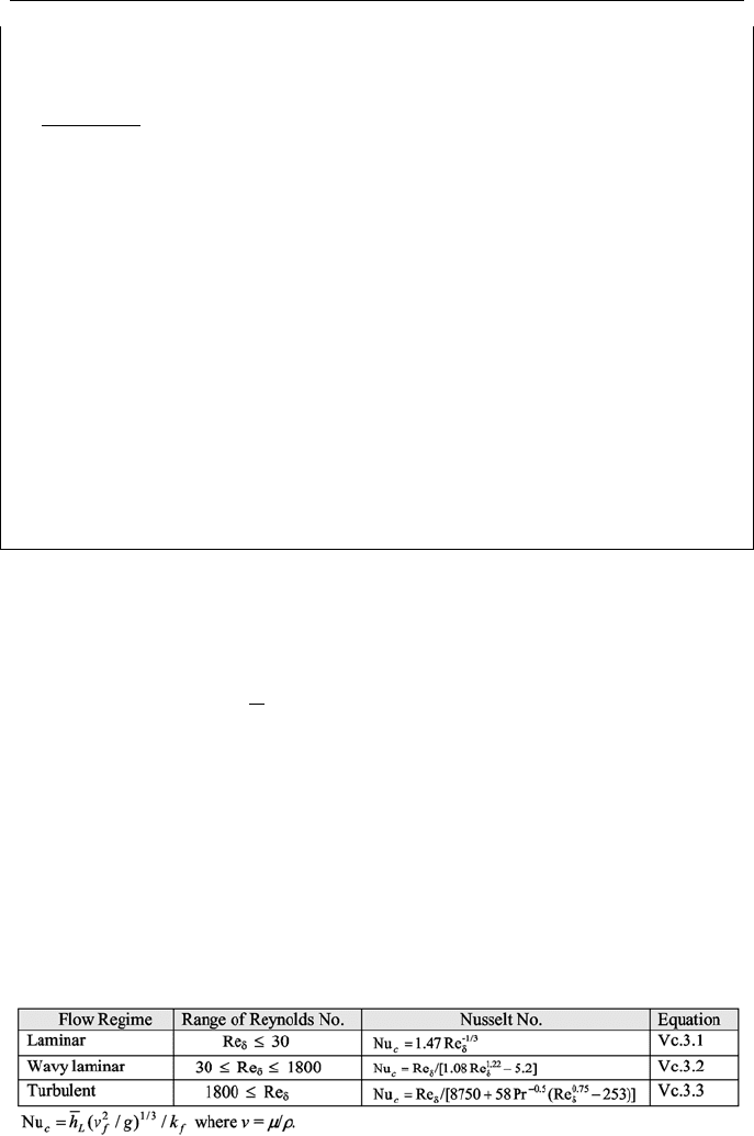
3.1. Condensation on Vertical Plates and Cylinders
By defining a condensation Nusselt number, Nu
c
also referred to as the condensa-
tion number, we may express the heat transfer coefficient in terms of the Reynolds
number. These are shown in the table below. In the wavy laminar region, being
the transition region between laminar and turbulent, the Kutateladze correlation
and in the turbulent region the Labuntsov correlation are recommended.

3. Empirical Solution 683
Example Vc.3.1. A vertical flat plate, 1.1 m long and 0.5 m wide maintained at
50 C is exposed to saturated steam at 0.5 bar. Find the total rate of heat transfer to
the plate and the condensate mass flow rate.
Solution: We first find T
sat
(0.5 bar) = 81.33 C then T
film
= (81.33 + 50)/2 =
65.67 C:
For steam at T
sat
= 81.33 C: h
fg
= 2305.4 kJ/kg and
ρ
v
= 0.308 kg/m
3
For water at T
film
= 65.67 C: k
f
= 0.659 W/m·K,
µ
f
= 429E-6 N·s/m
2
,
ρ
f
=
980 kgm/m
3
, c
pf
= 4.2 kJ/kg·K
Since T
s
<< T
sat
, we calculate need to find
fg
h
′
:
Ja = 4.2(81.33 – 50)/2305.4 = 0.057
fg
h
′
= 2305.4(1 + 0.68 × 0.057) = 2395 kJ/kg
h =
25.0
3
1.1)5033.81(6E429
3E2395659.0)308.0980(9808.9
943.0
¸
¸
¹
·
¨
¨
©
§
×−×−
××−×
= 4310 W/m
2
·K
)(
ssat
TTAhQ −=
= 4310 (1.1 × 0.5) × (81.33 – 50) = 74,268 W
fg
hQm
′
= /
= 74,268/2.395E6 = 0.031 kg/s
Finding Re
δ
= 4 m
/
µ
f
b = 4 × 0.031/(429E-6 × 0. 5) = 578 shows the flow regime
is actually wavy laminar. We should then use the heat transfer coefficient based
on the Kutateladze correlation as shown below:
3/121.22
į
į
į
)/(2.51.08Re
Re
)(4
)(Re
)(
gv
k
TTA
hb
TTA
hm
h
f
f
ssat
fgf
ssat
fg
L
−
=
−
′
=
−
′
=
µ
Solving for Re
δ
, we find Re
δ
= 716.5. Using this in the Kutateladze correlation,
we find:
L
h = 716.5 × 0.659/{(1.08 × 716.5
1.22
–5.2)[(429E-6/980)
2
/9.8]
1/3
} = 5340
W/m
2
·K
Revised values for Q
and m
are:
Q
= 5340 (1.1 × 0.5) × (81.33 – 50) = 92,016 W
m
= 92,016/2.395E6 = 0.0384 kg/s.
The same procedure used for vertical flat plates is applicable to vertical cylin-
ders if δ
L
<< 0.5D.
3.2. Condensation on Spheres, Horizontal Cylinders
and on Banks of Tubes
Correlations similar to Equation Vc.2.6 are obtained for condensation on radial
systems (Dhir & Lienhard):

684 Vc. Two-Phase Flow and Heat Transfer: Condensation
25.0
3
)(
)(
¸
¸
¹
·
¨
¨
©
§
−
′
−
=
DTT
hkg
Ch
ssatf
fgfgff
D
µ
ρρρ
Vc.3.4
where C = 0.815 for condensation on spheres and C = 0.729 for condensation on
horizontal tubes. Equation Vc.3.4 is also applicable to condensers, which consist
of banks of horizontal tubes with cold fluid flows inside the tubes and vapor con-
denses on the tubes. For film condensation inside horizontal tubes, C = 0.555.
Example Vc.3.2. Find the condensate flow rate for the following data of a power
plant condenser: P = 2 in Hg, D = 1¼ in, L = 28.5 ft, N
tube
= 16500, T
s
= 75 F.
Solution: We first find T
sat
(2 in Hg) = 101 F then T
film
= (101 + 75)/2 = 88 F
For steam at T
sat
= 101 F: h
fg
= 1036 Btu/lbm and
ρ
g
= 0.003 lbm/ft
3
For water at T
film
= 88 F: k
f
= 0.36 Btu/ft·h·F,
µ
f
= 1.9 lbm/ft·h,
ρ
f
= 62 lbm/ft
3
,
c
pf
= 1 Btu/lbm·F
Since T
s
<< T
sat
we need to find
fg
h
′
= h
fg
(1 + 0.68Ja)
Ja = 1 × (101 – 75)/1036 = 0.025 and
fg
h
′
= 1054 Btu/lbm
e now use Equation Vc.3.4 to find the average heat transfer coefficient over a sin-
gle tube:
D
h = 0.729 × {(32.2 × 3600
2
) × 62
2
× 0.36
3
× 1054/[1.9 × (101 – 75) ×
(1/12)]}
0.25
= 1525 Btu/ft
2
·h·F
)(
ssatD
TTAhQ −=
= 1525 × (
π
× 28.5 × 1.25/12) × (101 - 75) = 369,800 Btu/h
fg
hQNm
′
= /
tube
= 16,500 × 368,800/1054 = 5.8 Mlbm/h.
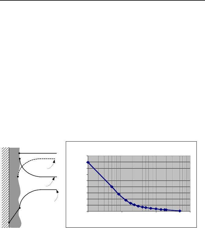
4. Condensation Degradation
The presence of even a small amount of noncondensable gas significantly de-
grades the rate of condensation heat transfer. As shown in Figure Vc.4.1, these
gases tend to migrate and accumulate near the colder surface, reducing the partial
pressure of the vapor and subsequently the corresponding saturation temperature
of the vapor. For containment response analysis, safety regulations require the use
of the Tagami correlation for the case of a LOCA and the Uchida correlation dur-
ing a MSLB analysis.
Tagami Correlation
Tagami, an empirical correlation, applies during the forced convection period fol-
lowing the blowdown phase of a LOCA. The key parameter in the Tagami corre-
Questions and Problems 685
lation is therefore time t
p
, which marks the end of the blowdown-induced forced
convection period. As such, the Tagami correlation is only applicable up to time
t
p
. The natural convection phase of a blowdown must be analyzed by using the
Uchida or the turbulent natural convection correlation depending on the value of
the Ra number. If h
maximum
is the heat transfer coefficient corresponding to time t
p
,
then the heat transfer coefficients at other times (t < t
p
) are obtained as
)/(
max p
tthh = . According to Tagami, h
maximum
itself is calculated from:
max
h =
()
0.62
/V
Tp
CU t
ªº
¬¼
, where U is the total blowdown energy released during t
p
and V
is containment free volume. In SI units, U is in J, t
p
in s, V in m
3
, and C
T
is 0.607.
Time t
p
is not known beforehand rather it should be obtained by iteration. A typi-
cal value for t
p
given a large dry containment is about 13 seconds.
Uchida Correlation
The Uchida correlation is given as a table of heat transfer coefficient versus the ra-
tio of air to steam mass. The maximum value is 1590 W/m
2
·K and the minimum
value is 11.4 W/m
2
·K.
Total Pressure
Gas Partial
Pressure
Steam Partial
Pressure
Fluid
Temperature
Uchida Condensation M odel
0
200
400
600
800
1000
1200
1400
1600
1800
0.1 1 10 100
Air Mass To Steam Mass Ratio
Heat Transfer Coefficient (W/m2-K
)
(a) (b)
Figure Vc.4.1. (a) Effect of noncondensable gas on pressure and (b) on h (Uchida model)
QUESTIONS
– Find the condensation mode for the following examples, a power plant con-
denser, steam condensation on spray droplets, steam condensation in a suppres-
sion pool, rain.
– Which condensation mode is more efficient, dropwise or film?
– Does dropwise condensation occur if a liquid wets the surface
– Can the heat transfer coefficient in condensation reach 10,000 Btu/ft
2
·h·F?
– Consider two condensers, one using horizontal tubes the other vertical tubes.
Cold water flows inside the tubes. If all other parameters are identical which
condenser is more efficient?

686 Vc. Two-Phase Flow and Heat Transfer: Condensation
– Inside the condensate film, where can you find the minimum shear stress
– The flow of the condensate film beyond what Reynolds number becomes turbu-
lent?
PROBLEMS
1. A vertical plate, 3 ft long and 5 ft wide is insulated from one side and the other
side is exposed to steam at 15 psia. The plate temperature is maintained at 120 F.
At what rate is condensate produced? [Ans.: Ja = 0.033, Re = 287.5, Nu = 7004,
h = 878 Btu/ft
2
·h·F, Q
= 126 kW, and m
= 0.116 lbm/s].
2. steam at 4 psia is condensing on a vertical plate 1 m long and 2 m wide. The
plate is at 50 C. Find
m
. [Ans.: Ja = 0.03, Re = 297, Nu 7621, h = 4968
W/m
2
·K, Q
= 278 kW, and m
= 0.12 kgm/s].
3. A steam condenser consists of a square array of 529 horizontal tubes, 1 in di-
ameter and 12 ft long. Tubes are maintained at 95 F to condense steam at 1 psia.
Find the condensate production rate. [Ans.: 27 lbm/min.]
4. Find the condensation heat transfer coefficient for saturated Freon-12 at 50 C
on a horizontal tube, having a diameter of 3 cm and maintained at 40 C. [Ans.:
1244 W/m
2
·C].
5. Consider condensation of benzene vapor at 1 bar on a vertical flat plate of
height 0.3 m. If the plate is kept at 60 C, find the condensation heat transfer coef-
ficient. At 1 bar, T
sat
= 80 C,
ρ
l
= 823 kg/m
3
,
ρ
g
= 2.74 kg/m
3
, h
fg
= 398 kJ/kg, c
p,l
= 1.88 kJ/kg·K,
µ
l
= 321E-6 N·s/m
2
, k
l
= 0.131 W/m·K. [Ans. 1270 W/m
2
·k].
6. Saturated steam at 1 atm is condensing on a horizontal tube at a rate of
300 kg/h. The tube is 2 m long and is maintained at 60 C. Find the tube diameter.
[Ans.: 13 cm].
7. A steam power plant produces 2700 MWe at a thermal efficiency of 29%. Find
the surface area and the number of tubes
8. A steel plate having L = 3 m, b = 1.5 m, and thickness of 0.5 cm is placed in
steam at 1 atm. Initially, the plate is at 80 C. Plot the plate temperature versus
time. Identify the simplifying assumptions made.
9. Water flows at a rate of 296 kg/h in a horizontal thin-walled tube (d = 0.025 m) at
25 C. Benzene vapor condenses at 1 bar on the tube. Find the rate of condensation
per meter. [Ans.: By iteration 24 kg/m·h].
VI. Applications
In this chapter we will study such important topics as heat exchangers, flow-
meters, and turbomachines. We will also evaluate the thermal hydraulics response
of systems to transients and heat generation from nuclear energy.
VIa
.
. Heat Exchangers
Heat exchanger (HX) is a generic term applied to a wide range of mechanical sys-
tems, which are designed for the purpose of exchanging thermal energy between
two streams of fluids separated by a solid surface. Some heat exchangers are used
as heat sinks including automotive inter-coolers, containment air coolers, cooling
towers, automotive radiators, and power plant condensers. Some other heat ex-
changers are used as a heat source including boilers, radiators for space heating,
and steam generators. For example, a nuclear plant utilizes many heat exchangers.
In a typical plant, feedwater heaters are employed in the balance of plant to im-
prove plant thermal efficiency. Also, other heat exchangers, such as the compo-
nent cooling water and shutdown cooling (also known as the residual heat re-
moval) system, provide a heat sink for the reactor during the shutdown period.
Finally, the service water heat exchanger provides a heat sink for the balance of
plant equipment. Heat exchangers have a hot side and a cold side separated by
tubes or plates. Heat transfer between the fluids in each side takes place through
the surface dividing the hot side and the cold side. Heat transfer may take place
between liquid and liquid, liquid and gas, and gas and gas. Heat exchangers may
also carry two-phase flow resulting in boiling or in condensation. Heat exchang-
ers may be operating at steady-state or transient conditions. Due to such design
variations, heat exchangers require careful analysis in design optimization as well
as in performance evaluation. In this chapter we will deal primarily with the
thermal aspects of tubular heat exchangers.
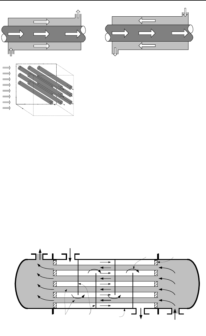
1. Definition of Heat Exchanger Terms
Concentric parallel flow heat exchanger consists of a tube surrounded by a
shell. In parallel flow heat exchangers, both hot and cold streams flow in the same
direction as shown in Figure VIa.1.1.
688 VIa Applications: Heat Exchangers
Tube-side Flow
Shell-side Flow
Tube
Shell
Inlet
Plenum
Exit
Plenum
Baffle Plate
Tube Sheet
Cross Flow
Figure VIa.1.2. Schematic of a shell and tube heat exchanger
Parallel Flow HX
Counterflow HX
x
y
z
Cross flow HX
Figure VIa.1.1. Schematics of parallel, counterflow, and cross flow heat exchangers
Concentric counter flow heat exchanger consists of a tube surrounded by a
shell. In counter flow heat exchangers, the hot and cold streams flow in opposite
directions as shown in Figure VIa.1.1.
Cross flow heat exchangers are generally used in gas-liquid applications.
They include tubes with a stream flowing parallel to the xy-plane and cross flow
parallel to the the yz-plane and perpendicular to the tube axis. The cross flow may
be mixed, as shown in Figure VIa.1.1, or unmixed by passing cross flow through
parallel plates.
Shell and tube heat exchanger is similar to the concentric heat exchanger.
However, shell and tube heat exchangers consist of multi tubes held in place by
baffle plates. These plates prevent tube vibration and enhance the rate of heat
transfer by diverting the shell-side fluid in a cross flow manner, as shown in Fig-
ure VIa.1.2. Shell and tube heat exchangers may be arranged in series to obtain

1. Definition of Heat Exchanger Terms 689
several cascaded shells. Each heat exchanger has a minimum of four ports. As
shown in Figure VIa.1.2, there is an inlet port and an outlet port in the hot side.
Similarly, there is an inlet and an outlet port in the cold side. Tubes are either
straight or bent in the form of a U. Heat exchangers including straight tubes have
an inlet plenum and an outlet plenum. Tubes are installed inside tube sheets,
which also act as barriers between the plenum fluids and the shell-side fluid.
Fouling factor f, is a measure of cleanliness of heat exchangers. Fluid streams
generally carry impurities. Sedimentation of the impurities over time leads to a
layer of deposit. This poses a resistance to heat transfer across the solid surface.
The sedimentation may also consist of sludge that would pit and corrode solid sur-
faces. Maintaining a closely monitored chemistry of the fluid stream and periodic
cleaning of heat exchangers is essential in ensuring proper operation of the device.
In a shell and tube heat exchanger, for example, cleaning of the shell side is espe-
cially challenging due to the presence of the baffle plates. In such cases, the
cleaner stream flows in the shell side, as cleaning the inside of the tubes is by far
easier. In power plants using large bodies of water as the heat sink, steam always
condenses on the tubes with river, lake, bay, or ocean water flowing in the tubes.
Fouling may be categorized as particulate fouling, crystallization fouling, corro-
sion fouling, biofouling, and chemical reaction fouling (Kakac). One way to ac-
count for fouling in the design process of heat exchangers is to increase the sur-
face area for heat transfer. Fouling factor has units of thermal resistance
ft
2
·h·F/Btu or m
2
·K/W. Some typical values are as follows:
Fluid f (m
2
·K/W) f (ft
2
·h·F/Btu)
Transformer oil 0.000176 0.0010
Engine lube oil 0.000176 0.0010
Crude oil 0.000352 0.0020
Heavy gas oil 0.000881 0.0050
Heavy fuel oil 0.001233 0.0070
Vegetable oil 0.000528 0.0030
Seawater 0.000176 0.0010
Brackish water 0.000528 0.0030
Muddy or silt water 0.000705 0.0040
River water (< 50 C) 0.001000 0.0060
Refrigerating liquid 0.000200 0.0011
From: Standards of Tubular Exchangers Manufacturers Association
Overall heat transfer coefficient is given in Equation IVa.6.8 for a clean con-
centric heat exchanger. To account for fouling resistance, Equation IVa.6.8
should be modified as follows:
1
1
2
)/ln(
1
−
»
¼
º
«
¬
ª
++++=
ooo
oio
i
i
ii
LhdLd
f
kL
dd
Ld
f
Lhd
UA
πππππ
= U
i
A
i
= U
o
A
o
VIa.1.1
690 VIa Applications: Heat Exchangers
where subscripts i and o stand for tube inside and tube outside, respectively. Tube
outside is also known as the tube bundle, shell side, or secondary-side. In Equa-
tion VIa.1.1, f
i
and f
o
are the tube-side and shell-side fouling factors, respectively.
Typical values of U for various streams are as follows.
Stream A / Stream B U (W/m
2
·K) U (Btu/ft
2
·h·F)
Condensing Steam / Water (Condenser & FWH) 1100 – 5500 200 – 1000
Freon 12 Condenser / Water 300 – 850 50 – 150
Water / Water 850 – 1700 150 – 300
Water / Oil 100 – 350 20 – 60
Gas / Gas 10 – 40 2 – 8
Cleanliness factor, C
F
is another measure of heat exchanger cleanliness and is
defined as the ratio of the overall heat transfer coefficient when a heat exchanger
is fouled, to the overall heat transfer coefficient of the clean heat exchanger, C
F
=
U
fouled
/U
clean
. When defining C
F
, we need not to consider any fouling (f
i
and f
o
) in
Equation VIa.1.1, rather calculate U
clean
and find U
fouled
from U
fouled
= C
F
U
clean
.
Heat Capacity, C is the product of mass flow rate and specific heat, C =
p
cm
having units of Btu/s·F or W/C.
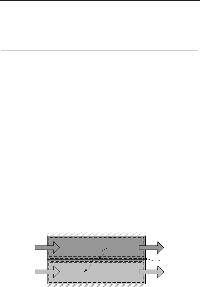
2. Analytical Solution
In this section we discuss steady-state operation of heat exchangers. As shown in
Figure VIa.2.1, we can assign control volumes to the entire hot-side, the cold-side
and the solid surface separating the hot and cold sides. In steady state conditions,
flow rates at the inlet and outlet ports for each control volume are equal hence:
houthinh
mmm
==
,,
VIa.2.1a
coutcinc
mmm
==
,,
VIa.2.1b
inhh
hm
,
,
incc
hm
,
,
Hot-side CV
Cold-side CV
outhh
hm
,
,
outcc
hm
,
,
Tube CV
hpouth
cT
,,
,
cpoutc
cT
,,
,
hpinh
cT
,,
,
cpinc
cT
,,
,
Q
Q
Figure VIa.2.1. Control volumes for the primary and secondary sides
The hot stream enters at an enthalpy of h
h
,
in
and leaves at an enthalpy of h
h,out
<
h
h,in
. If the heat exchanger shell is fully insulated so that there is no heat loss to
the environment, then under steady-state operation:

2. Analytical Solution 691
QQQ
sh
== VIa.2.2a
On the other hand, the cold side fluid enters at an enthalpy of h
c,i
and leaves at an
enthalpy of h
c,o
> h
c,i
. The gain in the cold stream energy is due to the transfer of
heat from the solid surface. In steady-state:
QQQ
sc
== VIa.2.2b
Substituting for the rate of heat transfer while assuming negligible potential and
kinetic energies, we find:
)(
,, outhinhh
hhmQ −=
VIa.2.3a
)(
,, incoutcc
hhmQ −=
VIa.2.3b
For a special case where each stream exits at the same phase as it entered the heat
exchanger, we may replace ∆h § c
p
∆T. Assuming variations in specific heat are
small and using c
p
= f(T
in
+ T
out
)/2, we can write the axial energy equations as:
)(
,, outhinhh
TTCQ −=
VIa.2.4a
)(
,, incoutcc
TTCQ −=
VIa.2.4b
So far we used the conservation equations of mass and energy in the axial direc-
tion. In the next section we use the conservation equation of energy in the trans-
verse direction for elemental control volumes to tie the hot-side and cold-side
temperatures by applying the overall heat transfer coefficient. The reason for us-
ing elemental control volume is that axial temperature profiles are generally not
linear functions of the heat exchanger length. As a result, we cannot generally use
average temperatures for the hot and cold side as:
]
22
[
,,,, outcincouthinh
TTTT
T
+
−
+
=∆
VIa.2.5
If it were possible, the rate of heat transfer would have been calculated from
TUAQ ∆=
. The simple relation given in Equation VIa.2.5 provides only an es-
timation of ∆T. In the next section we will see that ∆T is a logarithmic function of
the inlet and outlet temperatures referred to as the logarithmic mean temperature
difference (LMTD).
2.1. LMTD Method of Analysis
The analysis performed below applies to parallel flow heat exchangers as shown
in Figures VIa.2.2(a). Similar analysis can be performed for counterflow heat ex-
changers, shown in Figure VIa.2.2(b).