Massoud M. Engineering Thermofluids: Thermodynamics, Fluid Mechanics, and Heat Transfer
Подождите немного. Документ загружается.


712 VIa Applications: Heat Exchangers
Solution: a) First we calculate the rate of heat to be removed by the condenser.
Total power produced is:
ThermalH
WQ
η
/
= = 855/0.3 = 2850 MWth. The rate of heat to be removed in
the condenser is:
C
Q
= 2850 – 855 = 1995 MWth = 6.8069E9 Btu/h
- Tube-side mass flow rate: )/(
, ccpCi
TcQm ∆=
≅ 6.8069E9/(1 × 20) = 3.4E8
lbm/h
- Since T
c,out
= 68 + 20 = 88 F, the tube-side average temperature becomes T
c
=
0.5(68 + 88) = 78 F.
- To find U we need h
i
and h
o
. To find h
o
, we need tube temperature T
s
, which
varies along the tube length. We use T
s
calculated at average temperatures to rep-
resent the entire tube temperature. Since we do not have tube surface area, for
now we guess T
s
from T
c
and T
h
: T
s
= 0.5(T
c
+ T
h
) = 05(78 + 123) = 100.5 F
- Properties for both tube-side and shell-side at the related film temperatures are:
(T
film
)
c
= 0.5(T
c
+ T
s
) = 89.25 F. (T
film
)
h
= 0.5(100.5 + 123) = 111.75 F
T
(F)
ρ
(lbm/ft
3
) c
p
(Btu/lbm·F)
µ
(lbm/ft·h) k (Btu/ft·h·F) Pr
Shell 111.75 61.82 0.998 1.466 0.368 -
Tube 89.25 62.12 0.998 1.868 0.358 5.207
For tube bundle (shell-side) we also find h
fg
(123 F) = 1023.9 Btu/lbm and
ρ
g
(111.75 F) = 0.004 lbm/ft
3
- Since T
sat
> T
s
, we find Ja = c
p,h
(T
h
– T
s
)/h
fg
= 0.998 × (123 – 100.5)/1023.9 =
0.0219. Thus
'
fg
h = 1023.9(1 + 0.68 × 0.0219) 1039.17 Btu/lbm
3'
23
1/ 4 1/4
()
4.173 8 61.82 0.368 1039.17
0.729[ ] 0.729[ ]
( ) 1.466 (123 100.5) (1./12)
ff gffg
o
fh so
gkh
E
h
TTd
ρρ ρ
µ
−
×××
==
−×−×
= 1707 Btu/ft
2
·h·F
- To calculate h
i
we need to find Re
i
=
i
m
d
i
/(
µ
i
Na
i
). This in turn requires N and
a
i
, which are found as:
a
i
= 4/
2
i
d
π
= 3.14 × (0.93/12)
2
/4 = 0.004717 ft
2
.
N =
i
m
/(
ρ
i
V
i
a
i
) = 3.41E8/[62.12 × (9 × 3600) × 0.004717] = 35918
Re
i
= 3.41E8 × (0.93/12)/(1.868 × 35918 × 0.004717) = 83,500
h
i
= (k
i
/d
i
)[0.023 ]PrRe
4.08.0
ii
= (0.358 × 12/0.93) × [0.023 × 83500
0.8
× 5.207
0.4
]
= 1779.5 Btu/ft
2
·h·F

4. Analysis of Condensers 713
- We now calculate U
o
:
1 1
ln( / )
1 1 (1 / 12) ln(1 / 0.93) 1
[][ ]
2 0.93 1779.5 2 26 1707
oooi
o
ii s o
dddd
U
dh k h
− −
=+ += + +
××
= 765.5 Btu/ft
2
·h·F
- We also calculate ∆T
LMTD
=
[]
)88123/()68123(ln
)88123()68123(
−−
−−−
= 44.25 F
- To find total tube length, we use the overall energy balance
C
Q
= U
o
A
o
∆T
LMTD
= U
o
(
π
d
o
NL) ∆T
LMTD
- L =
LMTDoo
C
TNdU
Q
∆)(
π
=
25.4435918)12/1(5.765
9E8069.6
××××
π
= 21.2 ft.
- For two-tube pass per shell, L
pass
= 21.2/2 = 10.68 ft.
b) The tube-side pressure drop is found from Equation III.6.7:
2
2
20.2 2 2
0.184 21.2 (3.41E8 / 35918)
()
(0.93/12)2 Re 2 62.12 (32.2 3600 )(0.004717)
i
i
iici i
m
L
Pf
dga
ρ
∆= =
×××
= 408 lbf/ft
2
= 2.83 psi.
c) The rate of steam condensation is found from:
17.1039/9E8069.6/
'
==
fgCo
hQm
= 6.55E6 Btu/h
The results are summarized below:
d
i
d
o
h
i
h
o
U
o
L ∆T
LMTD
∆P
i
(in) (in) (Btu/h·ft
2
·F) (Btu/h·ft
2
·F) (Btu/h·ft
2
·F) (ft) (F) (psi)
0.93 1 1779.5 1707 765.5 21.2 44.25 2.83
Comment: we may use a transverse heat balance ()
ii s c
hA T T−= ()
oo s
h
hA T T−
to update tube temperature, T
s
. Note that due to high tube thermal conductivity,
we assumed T
si
= T
so
. The updated average tube temperature becomes T
s
= [T
h
+
(h
i
d
i
/h
o
d
o
)T
c
]/[1 + (h
i
d
i
/h
o
d
o
)] = 101.66 F. This is 1% larger than T
s
used in the
above analysis.
The above example shows the theoretical aspects of a condenser design. In
practice, such problems as tube fouling and the ingress of non-condensable gases
in the tube bundle need to be dealt with. The gas leakage in the tube bundle not
only increases the hot well total pressure but also, as discussed by Harpster, tends
to collect around some tubes, degrading condensation.

714 VIa Applications: Heat Exchangers
4.1. Condenser Design Optimization
For a given rate of heat transfer (
Q
) and bundle-side pressure [T
h
= T
sat
(P
steam
)],
we are interested in evaluating the effects of such parameters as tube velocity (V
i
),
tube diameter (d
i
and d
o
) and tube length (L) on the tube-side pressure drop and
subsequently the required pumping power. To perform this parametric evaluation,
we rearrange Equation VIa.3.1, noting that F = 1 for condensers:
Q
T
NLdhNLk
dd
NLdh
LMTD
oos
io
ii
∆
=++
)(
1
2
)/ln(
)(
1
πππ
VIa.4.1
where h
o
may be calculated from Equation Vc.3.4. Hence, it is treated here as a
constant. This is because the value of h
o
depends only on the properties of the
condensing fluid and the outside diameter of the tube. In Equation VIa.4.1, we
need to substitute for h
i
in terms of V
i
and d
i
. For this purpose, we use the defini-
tion of the Nusselt number:
()
()
()
0.8
0.4
0.8
0.4 0.8 0.8
0.023 / Pr
0.023 Pr /
ii i i i iii i i
ii i i ii
hd k Nu k Vd
kdV
ρµ
ρµ
ªº
«»
¬¼
==
=
Substituting for h
i
d
i
in Equation VIa.4.1 and rearranging, we obtain:
()
()
()
0.8
0.4 0.8 0.8
ln /
11
2
0.023 Pr /
oi
LMTD
soo
ii i i ii
dd
T
NL
Qkdh
kdV
π
ρµ
∆
=+−
ªº
§·
¨¸
«»
©¹
¬¼
VIa.4.2
Equation VIa.4.2 provides a relation between N and L. We can find N in terms of
d
i
and V
i
from an energy balance for the tube side:
N =
ii
incoutccpiiii
i
V
TTcd
Q
dV
m
ρ
ππρ
1
)()(
4
)(
4
,,,
22
»
»
¼
º
«
«
¬
ª
−
=
VIa.4.3
Substituting N from Equation VIa.4.3 into Equation VIa.4.2, we find tube length L
as:
()
»
»
¼
º
«
«
¬
ª
¸
¸
¹
·
¨
¨
©
§
∆
∆
¸
¸
¹
·
¨
¨
©
§
»
¼
º
«
¬
ª
−−
»
»
¼
º
«
«
¬
ª
=
i
LMTD
pii
ii
oos
io
iiii
ii
T
T
c
Vd
hdk
dd
k
Vd
L
ρ
µρ
4
1
2
/ln
/Pr023.0
2
8.08.04.0
2.02.1
VIa.4.4
As shown in Tables A.III.1 and A.III.2, the selection of tube or pipe outside di-
ameter and the specification of tube gage or pipe schedule results in the
determination of the inside diameter. Equation VIa.4.3 shows that, for a specified
tube size, the number of tubes is inversely proportional to the coolant velocity in
the tubes. On the other hand, Equation VIa.4.4 shows that tube length is nearly a
4. Analysis of Condensers 715
tubes. On the other hand, Equation VIa.4.4 shows that tube length is nearly a lin-
ear function of tube-side velocity.
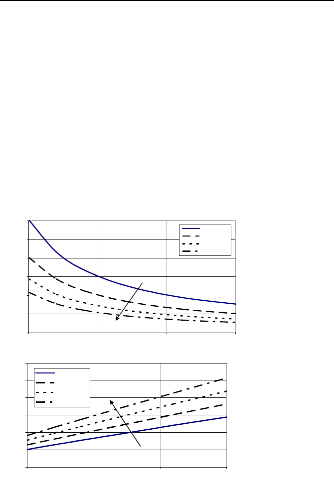
Using the above equations and the data of Example VIa.4.1, plots of tube
length and number of tubes versus tube diameter are obtained as shown in Fig-
ure VIa.4.2. As expected, the plots show that for a specified flow velocity, the
number of tubes increases, whereas tube length decreases with decreasing tube di-
ameter. Also, for a given tube diameter, tube length increases and number of
tubes decreases with increasing tube velocity. The same conclusion can be made
for tube-side pressure drop and pumping power. The pumping power is given as:
(/)
pump i
WPm
ρ
=∆
VIa.4.5
For a given tube diameter, the required pumping power decreases as the number of
tubes increases. This reduces operational cost. On the other hand, as shown by
Nahavandi, the initial capital cost increases with an increasing number of tubes.
Therefore, an optimized value for the number of tubes should be found to satisfy
cost criterion.
0
20000
40000
60000
80000
100000
120000
5 101520
Flow velocity in tube (ft/s)
Number of tubes
O.D.: 5/8"
O.D.: 3/4"
O.D.: 1"
O.D. 1 1/4"
O.D.
0
20
40
60
80
100
120
5 101520
O.D.: 5/8"
O.D.: 3/4"
O.D.: 1"
O.D.: 1 1/4"
Flow velocity in tube (ft/s)
Total tube length (ft)
O.D.
Figure VIa.4.2. Tube length and tube number versus flow velocity for various tube diame-
ters
716 VIa Applications: Heat Exchangers
T
h, in
Boiling water
C
i
r
c
u
l
a
t
i
n
g
w
a
t
e
r
Circulating water
from heat source
To steam turbine
From Feedwater pump
T
h, out
T
c
s
s
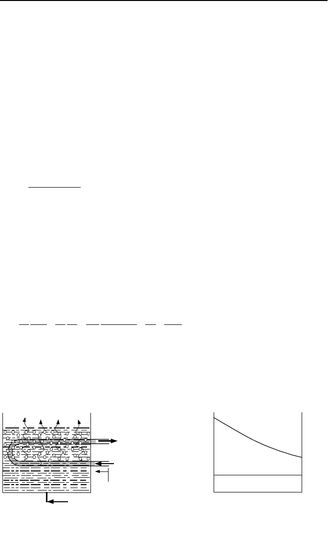
Figure VIa.5.1. Schematic of a steam generator
5. Analysis of Steam Generators
In the design of steam generators, the rate of heat transfer, inlet and outlet tem-
peratures, and flow rates are generally known quantities (Figure VIa.5.1). The
goal, therefore, is to calculate the heat transfer area of the tubes. In steam genera-
tors, the hot fluid generally flows in the tubes with water boiling in the tube bun-
dle. In this analysis we consider the secondary side to be at saturation condition
along the entire length of the tubes whether tubes are oriented horizontally or ver-
tically. To be consistent, we show tube side values with subscript i and secon-
dary-side values with subscript o, respectively. Also, T
h,in
, T
h,out
, and T
c
are tube
inlet, tube exit, and shell-side saturation temperatures, respectively. Known val-
ues are
Q
,
i
m
, T
h,in
, T
h,out
, T
c
, f
i
, f
o
, d
i
and d
o
. We calculate the steam generator ef-
fectiveness from:
cinh
outhinh
TT
TT
−
−
=
,
,,
ε
VIa.5.1
Having
ε
from Equation VIa.5.1, we can calculate NTU from NTU =
min
/UA C =
ln(1 )
ε
−− Therefore,
)1ln(
,
ε
−−=
ipi
cmUA
VIa.5.2
Combining Equations VIa.1.1 and VIa.5.2, writing the total tube length as
)/(
oo
dAL
π
= , and the surface area of the inside of the tubes as A
i
= d
i
A
o
/d
o
yields:
1
ln( / )
11
2
ooiooio
iio i o s o o oo
ddfdddf
dhA dA k A A hA
−
++ ++
ªº
«»
¬¼
= )1ln(
,
ε
−−
ipi
cm
VIa.5.3
Total tube surface area, A
o
is obtained from Equation VIa.5.3 provided h
i
and h
o
are substituted in terms of known quantities. We use the Dittus-Boelter correla-
tion (Equation IVb.3.4) for turbulent flow inside tubes to find h
i
:
5. Analysis of Steam Generators 717
3.0
8.0
Pr)
4
(023.0
i
ii
i
i
i
i
dN
m
d
k
h
µπ
=
VIa.5.4
where the exponent of the Pr number is changed to 0.3 as the fluid is cooling
down. Also physical properties in Equation VIa.5.4 are developed at the fluid
bulk temperature. The secondary side heat transfer coefficient h
o
may be found
from Rohsenow’s pool boiling correlation or the Chen correlation (Equations
Vb.4.1a and Vb.5.1b, respectively). Selecting the Rohsenow correlation, we find:
7.1
3/1
,,,
Pr
)(
/
o
ogof
o
fgo
o
op
fgfs
cs
g
g
h
AQ
c
hC
TT
C
»
»
¼
º
«
«
¬
ª
−
=−
ρρ
σ
µ
VIa.5.5
We now correlate the surface superheat to the secondary-side thermal resistance as
Q
AhA
f
TT
ooo
o
cs
)
1
( +=−
and substitute the result in Equation VIa.5.5:
)
1
(
ooo
o
AhA
f
+
3/1
3/2
7.1
3/1
,,,
1
Pr
)(
1
o
o
ogof
o
fgoop
fgfs
AQ
g
g
hc
hC
C
°
¿
°
¾
½
°
¯
°
®
»
»
¼
º
«
«
¬
ª
−
=
ρρ
σ
µ
VIa.5.6
Substituting Equation VIa.5.6 into Equation VIa.5.3 results in:
0
3
3/2
21
=++ CACAC
oo
VIa.5.7
where C
1
=
[]
1
,
)1ln(
−
−
ε
ipi
cm
,
C
2
3/2
7.1
3/1
,,,
3/2
1
Pr
)(
1
Q
g
g
c
hC
o
ogof
oc
oop
fgfs
°
¿
°
¾
½
°
¯
°
®
»
»
¼
º
«
«
¬
ª
−
=
ρρ
σ
µ
and
C
3
=
»
¼
º
«
¬
ª
++
s
ioo
i
i
o
ii
o
k
ddd
f
d
d
hd
d )/ln(
2
1
,
where g
c
is given in Chapter IIa. Equation VIa.5.7 is a non-linear algebraic equa-
tion that may be solved by Newton-Raphson iteration. The first guess for tube
area is obtained from an approximate solution (i.e., by assuming that the secon-

718 VIa Applications: Heat Exchangers
dary-side thermal resistance is negligible (A
o
)
Guess
= C
3
/C
1
). Upon solving Equa-
tion VIa.5.7, we can find the average tube length from L = A
o
/(
π
d
o
N).
Example VIa.5.1. The following data are given for a steam generator. Find a)
the average tube length L
tube
, b) tube side pressure drop, and c) shell side flow rate.
Data: d
i
= 0.654 in, d
o
= 0.75 in, T
h,in
= 604 F, T
h,out
= 550 F, P
h
= 2250 psia, P
c
=
850 psia, k
s
= 11.00 Btu/ft·h·F, N
tube
= 8485,
i
m
= 61E6 lbm/h, C
fs
= 0.015, c
p,o
=
1.24 Btu/lbm·F, f
i
= 0.0002437 ft
2
·h·F/Btu, f
o
= 0.0 ft
2
·h·F/Btu.
Solution: The solution, in a FORTRAN program, is included on the accompany-
ing CD-ROM.
The input data and results of calculation are summarized below.
Table VIa.5.1. Pertinent steam generator thermal hydraulic data
Total rate of heat transfer (Btu/h - MW):........................................ 4.386E9 - 1285.5
Tube inlet temperature (F - C): ....................................................... 604 - 318
Tube exit temperature (F - C):......................................................... 550 - 288
Tube-side pressure (psia - MPa): .................................................... 2250 - 15.51
Tube bundle-side pressure (psia - MPa):......................................... 850 - 5.86
Tube bundle-side temperature (F - C):............................................ 525.2 - 274
Total number of tubes: .................................................................... 8485
Tube outside diameter (in - mm):.................................................... 0.75 - 19.05
Tube wall thickness (in - mm): ....................................................... 0.048 - 1.22
Tube inside diameter (in - mm)....................................................... 0.654 - 16.61
Tube average heated length (ft - m): ............................................... 54.16 - 16.5
Tube heat transfer area (ft
2
- m
2
):.................................................... 90,232 - 8383
Overall heat transfer coefficient (Btu/h·ft
2
·F - W/m
2
·C): ................ 1041 - 183.3
The log mean temperature difference, ∆T
LMTD
(F - C): ................... 46.7 - 25.9
Effectiveness:.................................................................................. 0.684
Tube-side thermal resistance (h·ft
2
·F/Btu - m
2
·C/W): ..................... 0.0001744 - 0.00099
Tube-wall thermal resistance (h·ft
2
·F/Btu - m
2
·C/W):..................... 0.0003950 - 0.00224
Tube bundle-side thermal resistance (h·ft
2
·F/Btu - m
2
·C/W): ......... 0.0001475 - 0.00084
Tube-side fouling resistance (h·ft
2
·F/Btu - m
2
·C/W):...................... 0.000 - 0.000
Tube bundle-side fouling resistance (h·ft
2
·F/Btu - m
2
·C/W):.......... 0.0002437 - 0.00138
An alternative derivation for determination of the required surface area for the
tubes takes into account the energy balance for an elemental control volume due to
the change in temperature from tube inlet to tube exit (Nahavandi). Similar corre-
lations can then be used for heat transfer coefficients and the resulting differential
equation is integrated from tube inlet to tube outlet to obtain the required surface
area. (see Problem VIa.18).
In steam generators, we often need to find the temperature of the hot fluid as it
moves inside the tubes and transfers energy to the secondary side. This is shown
in the next example.
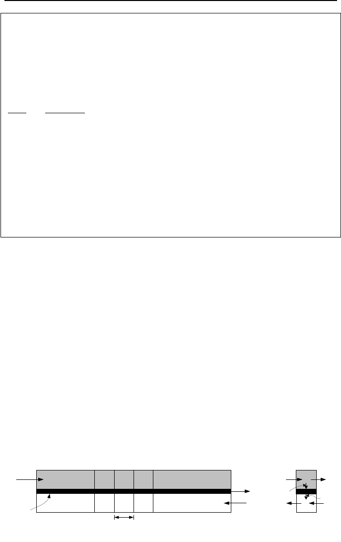
6. Transient Analysis of Concentric Heat Exchangers 719
i
Stream A
Stream B
T
B,in
T
A,in
x
dx
i
i+1i-1
i-1
i+1i
Tube
i
Q
i-1
.
Q
.
Wall
.
Q
s,i
.
Q
i,s
Figure VIa.6.1. Nodalization of a concentric heat exchanger
Example VIa.5.2. Hot liquid is flowing steadily at a rate of m
inside the tubes of
a steam generator having N tubes of outside diameter d
o
. The secondary side is
boiling, resulting in an overall heat transfer coefficient of U
o
that remains uniform
along the tube. Find the tube-side temperature profile as a function of flow path.
Solution: Applying Equation IIa.6.4-1 to the single-phase liquid inside the tubes
over element ds, results in:
()
sath
p
ooh
TT
cm
UdN
ds
dT
−−=
π
where s is an element of length in the flow direction and T
sat
is the secondary-side
saturation temperature. Since m
, U
o
, and T
sat
remain constant, we can integrate
from T
h,in
(s = 0) to T(s) to find:
()
()
(
)
*
/
,,
1
ls
satinhinhh
eTTTsT
−
−−−= VIa.5.8
where s is an element of length along the tube and l
*
is given by l
*
=
m
c
p
/(
π
Nd
o
U
o
). This result is not applicable if liquid boils in the tube-side or liq-
uid does not boil in the secondary side.
6. Transient Analysis of Concentric Heat Exchangers
A transient during heat exchanger operation is generally caused by throttling a
valve located on the discharge line of the pump feeding the tube or the shell side.
Heat exchanger transients also take place during starting or stopping the pump.
Transients imposed by valves and pumps affect flow rate. Inlet temperatures to
tube or shell may also change due to the loss of a feedwater heater if located up-
stream of the heat exchanger. In this analysis we consider concentric parallel and
counterflow heat exchangers and divide the exchanger along its length to several
nodes. Both streams are assumed to be incompressible and average fluid proper-
ties are used. By explicitly modeling the tube region, thermal inertia of the tube
material would then appear in the formulation. Shown in Figure VIa.6.1 is the
schematic of a concentric heat exchanger, divided into N nodes but only three
nodes are shown. Node i, for example, receives mass and energy from node i - 1,
as carried by the mass flow rate of stream A and, in turn, delivers mass and en-
thalpy to node i + 1. Due to the liquid incompressibility, mass flow rate into node
i equals the mass flow rate into node i + 1, as only energy would accumulate in

720 VIa Applications: Heat Exchangers
node i. There is also a transverse energy transfer out of node i of stream A,
through the tube surface into node i of stream B. Hence, the energy balance in the
axial direction for element i in stream A yields:
()
ivisiii
Tcm
t
QdQQ
∂
∂
=−−
−−
1
VIa.6.1
where in Equation VIa.6.1, m
i
is the mass of stream A fluid in control volume i.
Note that in this derivation, we ignored heat conduction in the fluid compared with
the rate of energy transfer by convection. Replacing m
i
=
ρ
i
A
i
dx, where A
i
is the
flow area of stream A, and expanding the second term in the left side, Equa-
tion VIa.6.1 becomes:
()
[]
iiv
i
si
i
ii
TcAdx
t
Qddx
x
Q
QQ
,
1
11
ρ
∂
∂
∂
∂
=−
¸
¸
¹
·
¨
¨
©
§
+−
−
−
−−
Since fluid is incompressible, we express enthalpy in terms of specific heat and
temperature. Parameters
ρ
i
, c
p,i
, and A
i
are also constant. The formulation for
stream A becomes:
()
()
A
A
TAdxc
t
QddxTVAc
x
vsip
ρ
∂
∂
ρ
∂
∂
=−−
−
Substituting for the transverse energy term, yields:
()
()
A
AA
A
)()P( TAdxc
t
TThdxdxTVAc
x
vsp
ρ
∂
∂
ρ
∂
∂
=−−−
where P is the perimeter (P =
π
d) and h is the heat transfer coefficient. Note that
we have represented the elemental tube since we are using average values for
properties,
ρ
, c
p
, c
v
, and h remains constant. Since A
A
and V
A
are also assumed to
be constant, we can write:
()
0
P
A
A
A
A
A
=−
¸
¸
¹
·
¨
¨
©
§
+
¸
¸
¹
·
¨
¨
©
§
+
s
vv
p
TT
Ac
h
x
T
c
c
V
t
T
ρ∂
∂
∂
∂
VIa.6.2
Similarly, the differential equation describing axial energy of stream B becomes:
()
0
P
B
B
B
B
B
=−
¸
¸
¹
·
¨
¨
©
§
−
¸
¸
¹
·
¨
¨
©
§
+ TT
Ac
h
x
T
c
c
V
t
T
s
vv
p
ρ∂
∂
λ
∂
∂
VIa.6.3
where in this equation,
λ
= 1 for parallel flow and
λ
=−1 for counterflow heat
exchangers. The rate of change of energy in the ith node of the tube material is
due to the exchange of energy with streams A and B, hence the energy equation
for the heat exchanger tube material becomes:

6. Transient Analysis of Concentric Heat Exchangers 721
()
AB
AB
(P ) (P )
() 0
() ()
s
ss
ss
Th h
TT TT
tcA cA
∂
∂ρ ρ
−−+−=
VIa.6.4
Equations VIa.6.2, VIa.6.3, and VIa.6.3 constitute an approximate formulation for
transient analysis of parallel and counterflow heat exchangers. Various solution
methods are proposed for this set of equations. For example, Li finds an exact so-
lution for the parallel flow heat exchanger by using Laplace transforms. Lorenzini
applies the finite element method while Romie uses several dimensionless ratios
to describe the exit temperature response to a unit step change in the inlet tempera-
tures. The following solution is based on the finite difference method. The en-
ergy equations for stream A, in finite difference form is:
()
0
P
1
,
1
,A
A
1
1,A
1
,A
A
,A
1
,A
=−
¸
¸
¹
·
¨
¨
©
§
+
∆
−
¸
¸
¹
·
¨
¨
©
§
+
∆
−
++
+
−
++
n
is
n
i
v
n
i
n
i
v
p
n
i
n
i
TT
Ac
h
x
TT
c
c
V
t
TT
ρ
The finite difference form of the tube wall energy equation becomes:
()()
0
)(
)P(
)(
)P(
1
,B
1
,
B
1
,
1
,
A
,
1
,
=−+−−
∆
−
++++
+
n
i
n
is
s
n
is
n
iA
s
n
is
n
is
TT
cA
h
TT
cA
h
t
TT
ρρ
and the finite difference form of stream B energy equation, considering a counter-
flow heat exchanger is:
()
0
P
1
,B
1
,
B
1
1,B
1
,B
B
,B
1
,B
=−
¸
¸
¹
·
¨
¨
©
§
−
∆
−
¸
¸
¹
·
¨
¨
©
§
−
∆
−
++
+
+
++
n
i
n
is
v
n
i
n
i
v
p
n
i
n
i
TT
Ac
h
x
TT
c
c
V
t
TT
ρ
These equations can be simplified by introducing dimensionless constants for
stream A:
()
tx
V
c
c
v
p
∆∆
¸
¸
¹
·
¨
¨
©
§
=
/
A
A
1
α
;
312
1
ααα
++= ;
α
3
= t
Ac
h
v
∆
¸
¸
¹
·
¨
¨
©
§
A
P
ρ
for the tube material:
t
cA
h
s
∆=
)(
)P(
A
1
ρ
σ
;
312
1
σσσ
++= ; =
3
σ
t
cA
h
s
∆
)(
)P(
B
ρ
and for stream B:
t
Ac
h
v
∆
¸
¸
¹
·
¨
¨
©
§
=
B
1
P
ρ
β
;
312
1
βββ
++= ; =
3
β
()
tx
V
c
c
v
p
∆∆
¸
¸
¹
·
¨
¨
©
§
/
B
B
λ
.
Definition of these dimensionless coefficients reduces the finite difference equa-
tions to: