Massoud M. Engineering Thermofluids: Thermodynamics, Fluid Mechanics, and Heat Transfer
Подождите немного. Документ загружается.


4. Charging and Discharging Rigid Volumes
211
Having vapor pressure and relative humidity, we can find the humidity ratios. For
air entering the tower P
v3
= 0.35(0.43) = 0.15 psia. For air leaving the tower, P
v5
=
0.95(0.69) = 0.65 psia. Therefore,
3
ω
= 0.622(0.15)/(14.7 – 0.15) = 0.00641. Similarly,
4
ω
= 0.622(0.65)/(14.7 – 0.65) = 0.0287.
Substituting in Equation IIc.4.8, we get:
1E8(77.98 63.01)
57E6 lbm/hr
(0.0287 1100.8 0.0064 1094.3) (0.0287 0.0064)38 0.171(90 75)
a
m
−
=≈
×−× − − + −
Substituting in Equation IIc.4.6, we find
5
(0.0287 0.0064)57E6 1.3E6 lbm/hr.m =− ≈
Thermal Design of Containment
The containment building is the last barrier against release of radioactive materials
to the environment in the case of a hypothetical accident. There are several types
of containments, the design of which depends on the type of the nuclear reactor
and the architect engineer. For example, to deal with thermalhydraulic loads,
BWR containments are equipped with a suppression pool while some types of
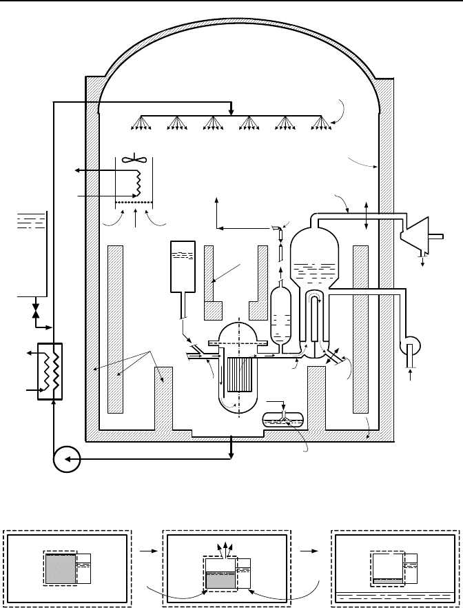
PWR containment utilize large blocks of ice. Figure IIc.4.4 shows the schematic
of a PWR large, dry containment. With respect to thermalhydraulic loads, PWR
containments should withstand the consequences of two types of postulated acci-
dents; a loss of coolant accident (LOCA) and a main steam line break (MSLB). A
LOCA refers to a primary side pipe break of the hot or the cold leg, such as a dou-
ble-ended guillotine break at location a-a in Figure IIc.4.4, for example. A MSLB
refers to rupture of the main steam line inside the containment such as a double-
ended guillotine break at break location b-b. The LOCA and MSLB are referred to
as design basis accidents.
The PWR containment analysis for both LOCA and MSLB requires two key
inputs, mass flow rate and enthalpy of the fluid flowing through the break into the
containment. We analyze containment in both the design phase and during opera-
tion. In the design phase, our intention is to find the free volume, that can ac-
commodate the mass and energy transfer so that the peak pressure and temperature
are kept below the specified design limits. During operation, containment analysis
is required subsequent to any modification that may impact the containment re-
sponse to above postulated accidents. During plant operation, we therefore seek
containment peak pressure and temperature for given free volume.
A containment building, or simply containment, is generally equipped with ac-
tive safety systems such as spray and air coolers to provide a heat sink in the case
of an accident. The containment structure and internals also absorb a substantial
amount of energy during an accident, thus they are referred to as passive heat
sinks. In the case of the containment structure, some heat is also transferred to the
surroundings through the primer, paint, steel liner plate, and the one meter thick
concrete wall. The heat source for the containment depends on the postulated ac-
cident and the reactor type. For a LOCA, the heat source includes the latent heat

IIc. Thermodynamics: Mixtures
212
of the primary-system inventory, the sensible heat stored in the reactor system
metals, and the decay heat of the fission fragments. For a MSLB in a PWR, the
heat source includes the latent heat of water inventory of the secondary side, the
sensible heat from the stored energy in the steam generator metals, and the heat
transfer from the primary side through the tubes. Additionally, some exothermic
chemical reactions, such as zirconium reacting with water at high temperatures,
add to the containment thermal load. Handling the hydrogen produced in such
chemical reactions is another constraint for the design of the containment. This
discussion is summarized in Table IIc.4.1.
Below we perform a containment response analysis for both LOCA and MSLB
to find peak pressure and temperature for a PWR large dry containment. Similar
analysis exists for a BWR containment.
Table IIc.4.1. Factors affecting PWR containment response to accidents
Event Heat Source Heat Sink Source of Emergency Cooling
LOCA
Decay heat*
Coolant internal energy
Metal Stored energy
Reactor pump heat
Exothermic reactions
Containment spray
Containment air coolers
Passive heat sinks
High-pressure safety injection
Low pressure safety injection
Safety water tanks
MSLB Latent heat of coolant
Stored energy
Exothermic reactions
Containment spray
Containment air coolers
Passive heat sinks
Auxiliary feedwater
* See description in Chapter VIe.
Case A: Containment Response Analysis to LOCA in PWRs
In this case, we seek peak pressure for given containment volume. To obtain pres-
sure and temperature versus time, we need to have the mass flow rate and enthalpy
of the flow at the break as a function of time. We leave this rigorous treatment of
containment analysis to Chapter VId. For now, we include the primary side of the
reactor in the containment control volume (Figure IIc.4.5). For this control vol-
ume, there is no flow entering or exiting and no shaft or expansion work. We then
find containment peak pressure by integrating the simplified form of Equa-
tion IIa.8.1 from the initial to the final state. The initial state refers to the primary
system being intact. The final state refers to a condition at which the primary side
has discharged most of its inventory to the containment and has reached thermal
equilibrium with the containment.
In the analysis that follows, m
v1
is the initial mass of water vapor in the con-
tainment atmosphere, m
w1
is the initial mass of water in the primary-system. Simi-
larly, V
v1
is the free volume of the containment (according to the Dalton’s model,
V
v1
= V
a
) and V
w1
is the volume of the primary-system. Finally, m
w2
is the total
mass of water and steam in V
v1
+ V
w1
. Similar subscripts are used for the internal
energy terms.
4. Charging and Discharging Rigid Volumes
213
Reactor
Vessel
Steam
Generator
Pressurizer
Safety
Water
Tank
Steel Liner
Passive
Heat Sinks
Containment Spray
Base Mat
Sump
Hot Leg
Cold Leg
Air Coolers
N
2
Cold
Leg
Refueling Water
Tank
Main Steam Line
Main
Turbine
To Condenser
From
Condenser
Main
Feedwater
Spray Nozzle
Containment Dome
Pedestal
a
b
To Quench Tank
Safety-Relief Valve
Quench Tank
From
Pressurizer
a
b
To Heat Sink
To Heat Sink
Figure IIc.4.4. Schematic of a PWR Large Dry Containment
P
2
T
2
P(t)
T (t)
m
v
(t)
m
a
Primary-
Side
Secondary-
Side
m
w2
m
a
P
1
T
1
m
w1
m
a
m
v1
time time
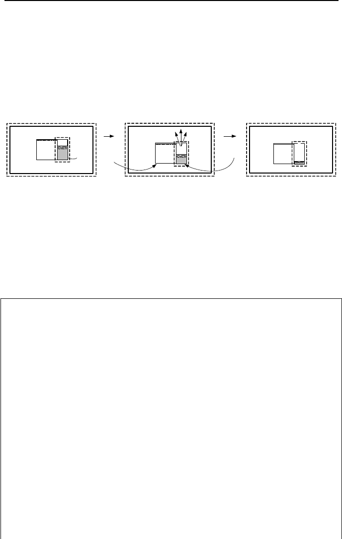
Figure IIc.4.5. Depiction of a LOCA in a PWR containment
From Equation IIa.8.1 for water and steam we find:
211 wwv
mmm =+ IIc.4.9
From Equation IIa.8.2 for air, water, and steam we find (see Table IIc.4.1 for
sources and sinks of energy):

IIc. Thermodynamics: Mixtures
214
111 11
222
a a v v w w Decay Metal Pump Spray Cooler Structure
aa w w
mu m u m u Q Q Q Q Q Q
mu m u
++ +++−−−
=+
To maximize the energy transfer to the containment atmosphere, we drop all en-
ergy removal terms due to the action of spray and air cooler, as well as the heat ab-
sorption in the containment structure:
22211111 wwaaPumpMetalDecaywwvvaa
umumQQQumumum +=+++++
IIc.4.10
We have three unknowns, m
w2
, u
w2
, and T
2
. To complete the set, we use the vol-
ume constraint:
v
w2
= (V
w1
+ V
v1
)/m
w2
IIc.4.11
Since the mass transfer in a LOCA from the primary side to the containment is
primarily in the form of a two-phase mixture, we expect that the containment at-
mosphere becomes saturated in steam, yielding 1
2
=
φ
. To solve the above set of
three equations, we substitute for m
w2
from the continuity equation into the energy
equation and the volume constraint. We then assume a steam quality x
2
, and iter-
ate on T
2
between the two equations and the steam tables.
Example IIc.4.5. The primary side of a PWR has a volume of 11,000 ft
3
(311.5
m
3
). The reactor is operating at an average pressure of 2200 psia (15 MPa) and
average temperature of 575 F (302 C). Containment initial conditions are given as
16.5 psia (114 kPa), 125 F (52 C), and 20% relative humidity. Containment vol-
ume is 2E6 ft
3
(56,636 m
3
). Find final equilibrium pressure following a LOCA.
Solution: For containment, we first find the initial steam partial pressure:
psia388.09424.12.0)125(
1
=×==
gv
PP
φ
(2.67 kPa)
We now find initial masses and energies for which we first find the thermody-
namic properties as follows:
P T P
g
(T)v u
(psia) (F) (psia) (ft
3
/lbm) (Btu/lbm)
0.388 125 1.9424 898 1052.4
2250 575 – 0.0221 569.84
m
v1
= V
v1
/v
1
= 2,000,000/898 = 2227 lbm. The air mass is found from m
a
=
P
a1
V
a
/(R
a
T
1
). Since air pressure is P
a1
= P
1
– P
v1
= 16.5 – 0.388 = 16.11 psia:
lbm150015
)125460)(97.28/1545(
)102()14411.16(
V
6
1
11
=
+
×××
==
TR
P
m
a
aa
a
(68,047 kg)

4. Charging and Discharging Rigid Volumes
215
We now find the mass of water in the primary system as m
w1
= V
w1
/v
w1
=
11,000/0.0221 = 497737 lbm. Hence,
m
w2
= m
v1
+ m
w1
= 2227 + 497737 = 499,964 lbm.
From Equation IIc.4.11 we find v
2
= (2,000,00 + 11,000)/499,964 = 4 ft
3
/lbm.
Having v
2
, we guess a value for T
2
and read v
f2
and v
g2
from the steam tables to
find x
2
as x
2
= (v
2
– v
f
)/v
fg
.
vaa
wwwwvv
cm
umumum
TT
221111
12
)( −+
+=
where we have only considered the coolant internal energy (see the comment be-
low). We summarize the data we have found so far:
m
a
m
v1
m
w1
u
v1
u
w1
m
w2
v
w2
lbm lbm lbm Btu/lbm Btu/lbm lbm ft
3
/lbm
150015 2227 497737 1052.4 569.84 499,964 4
m
v1
u
v1
+ m
w1
u
w1
= 2227(1052.4) + 497737(569.84) = 2.859E8 Btu (3E8 kJ)
We begin the iteration process by assuming a value for T
2
and find an updated
value for T
2
as follows:
T
2
v
f
v
fg
u
f
u
fg
x
2
u
w2
T
2
(F) (ft
3
/lbm) (ft
3
/lbm) (Btu/lbm) (Btu/lbm) (–) (Btu/lbm) (F)
268.10 0.0172 10.3941 236.90 854.62 0.383 564.4 270
Since
ε
= (270 – 268.10)/268.10 = 0.7%, we use 270 F as a reasonably accurate fi-
nal temperature. Having final equilibrium temperature, we find:
P
w2
= P
g
(268.1 F) = 40.73 psia (281 kPa)
P
a2
= m
a
R
a
T
2
/(V
w1
+ V
v1
) = 150015×53.33(268.1 + 460)/2,011,000 =
8.68 psia (59.8 kPa)
Therefore, final equilibrium pressure is P
2
= P
w2
+ P
a2
= 40.73 + 8.68 =
49.4 psia (341 kPa).
Comment: In this solution, we only accounted for the internal energy of the pri-
mary side coolant and did not consider the heat addition from all other sources. If
the pumps are tripped, their contribution to the energy equation is eliminated.
However, inclusion of the decay heat and the sensible heat of the reactor structure
and its internals (metal stored energy) requires detailed knowledge of the system.
If we assume that the contribution from the decay heat and stored energy in the
above example is Q
Total
= 25E6 Btu, we may follow the same steps outlined above
to find T
2
= 276 F and P
2
= 64.7 psia. The method of obtaining the pressure and
temperature trends for containment response is discussed in Chapter VId.
Case B: Containment Response Analysis to MSLB in PWRs
In this case, we also seek the final equilibrium pressure for given containment
volume, where the initial state refers to the steam generator being intact. The final
state refers to thermal equilibrium between the broken steam generator and the
containment. The control volume we choose consists of the containment and the
IIc. Thermodynamics: Mixtures
216
broken steam generator (Figure IIc.4.6). As explained in Case A, the selection of
such a control volume eliminates the need for having the break mass flow rate and
enthalpy versus time. On the other hand, such treatment precludes us from pre-
dicting the trend of the containment pressure and temperature during the event.
The same sets of equations we developed for LOCA are also applicable here.
However, in a MSLB, mass transfer from the broken steam generator to the con-
tainment is primarily in the form of dry steam. Therefore, we expect that the con-
tainment atmosphere becomes superheated in steam, yielding
1
2
<
φ
.
P
1
T
1
P
2
T
2
P(t)
T (t)
m
w1
m
a
m
v1
m
a
Primary-
Side
Secondary-
Side
m
v2
m
a
m
v
(t)
time time
Figure IIc.4.6. Depiction of a MSLB in a PWR containment
In this case, like Case A, we use the Dalton law of partial pressures for volume
constraint. However, we calculate the partial pressure of the superheated steam
from the ideal gas law, per Equation IIc.4.5. This is a reasonable approximation in
the range of interest for pressure and temperature:
P
2
= m
a
R
a
T
2
/(V
v1
+ V
w1
) + m
v2
R
v
T
2
/(V
v1
+ V
w1
) IIc.4.12
Example IIc.4.6. The secondary side of a PWR steam generator has a volume of
227 m
3
of which 75 m
3
is water. Steam generator pressure is 6.21 MPa. Initial
containment pressure, temperature, and relative humidity are 0.101 MPa, 50 C,
and 50%, respectively. Containment volume is 56,636 m
3
. Find the final equilib-
rium pressure and temperature following a MSLB. The amount of heat transferred
from the primary side to the secondary side is 897.6E8 J.
Solution: The initial vapor mass in the containment is found from
1
(50 C) 0.5 0.0123 0.00615 MPa
vg
PP
φ
==×=
We can find vapor mass from either the steam tables or the ideal gas law. From
the steam tables
v(0.00615 & 50 C) = 24.7 m
3
/kg.
Hence, the vapor mass is found as:
m
v1
= 56,636/24.7 = 2293 kg
From the ideal gas law, m
v1
= 6150×56,636/[(8314/18)×(273 + 50)] = 2335 kg.
The error in the calculation of vapor mass by using the ideal gas law is less than
2%. Similarly, for air mass
m
a
= (101000 – 6150)× 56,636/[(8314/28.97)×(273 + 50)] = 58,000 kg

4. Charging and Discharging Rigid Volumes
217
The initial mass of water and steam in the secondary side of the steam generator
can be calculated from the specific volumes, found from the steam tables. For wa-
ter, m
f1
= 75/0.0013 = 57,692 kg. For steam, m
g1
= (227 – 75)/1.69 = 4,841 kg.
Therefore, m
w1
= 4841 + 57,692 = 62533 kg. We also find x
1
= m
steam
/m
water
=
4841/62533 = 0.077. Therefore,
u
w1
= 1216.75 + 0.077 × 1370.79 = 1322.86 kJ/kg.
To summarize;
m
a
m
v1
m
w1
u
v1
u
w1
m
v2
(kg) (kg) (kg) (kJ/kg) (kJ/kg) (kg)
58,000 2293 62,533 2441.36 1323 64,826
We now guess T
2
, and find P
v2
, from Equation IIc.4.12. Assuming T
2
= 210 C we
find P
v2
:
2v
P = [67826 × 462 × 483/56863] = 0.254 MPa
We use the calculated P
v2
and the assumed T
2
to find u
v2
from the steam tables as
u
w2
= 2,667 kJ/kg. Having the final internal energies, the final temperature can be
found from Equation IIc.4.10:
vaa
wwwwvv
cm
umQumum
TT
22SecondaryPrimary1111
12
)( −++
+=
−
Substituting values for masses, internal energies, and heat transfer between pri-
mary and the secondary:
2
(2293 2441.36 62,533 1323 0.898E8) 64,826 2.667
50 176 C
58000 0.713
T
×+×+ −×
=+ =
×
We continue the iteration until the convergence criterion is met. The final answer
is T
2
= 200 C and P
2
=0.393 MPa.
Comment: This is a useful method to find the final state inside the containment
following a MSLB (or a LOCA). In practice, the conservation equations of mass
and energy are integrated over a small time step to obtain u and v. The corre-
sponding P and T are found in a pressure search process. This process is repeated
until the end of the specified duration is reached.
QUESTIONS
− What is the difference between the Dalton and the Amagat model?
− Apply the Amagat model to Example IIc.1.2. What conclusion do you reach?
− In a containment of a nuclear plant, the relative humidity is measured as 35%
and in the containment of another plant, it is measured as 70%. If both con-
tainments are at the same temperature and total pressure, which containment
has higher steam pressure? If both containments have also equal volumes,
which containment has higher air mass?
− Consider an unsaturated moist air at total pressure P, temperature T, and rela-
tive humidity
φ
. What is the significance of P
g
(T) and of T
g
(P
v
)?

IIc. Thermodynamics: Mixtures
218
− Is the dew point temperature reached in an isochoric or an isobaric process?
− Describe the humidification process.
− Consider a fully insulated system consisting of two regions. The first region
contains water at P
1
and T
1
. This region is separated from the second region by
a thermally conducting membrane. The second region contains moist air also at
P
1
and T
1
with
φ = φ
1
< 1. The membrane is now removed and
φ
2
= 1. Is P
2
>
P
1
?
− Why is there a need for makeup water in the operation of cooling towers?
− Consider the large dry containment of a PWR. There are many internals in the
containment such as pedestals, pipe supports, polar crane, stairways, etc. The
obvious disadvantage of the containment internals is to reduce the free volume
of the containment. From a thermodynamic point of view, what is the advan-
tage of having the internals in the containment during a design basis accident?
− With respect to containment response, what are the two major differences be-
tween a LOCA and a MSLB?
PROBLEMS
1. A tank, having a volume of 5 m
3
, is filled with N
2
and 2 kg of CO
2
at a pressure
and temperature of 150 kPa and 50 C, respectively. Find the partial volumes ac-
cording to the Amagat and the partial pressures according to the Dalton model.
2. A rigid tank contains 1 kg of nitrogen at 38 C and 2 MPa. We now add oxygen
to the tank in an isothermal process until the pressure in the tank reaches 2.76 MPa.
Find the mass of oxygen that entered the tank in this process. [Ans.: 0.35 kg].
3. Consider a room having a volume of 75 m
3
maintained at P = 1 atm, T = 25 F
and
φ
= 70%. a) Use the Dalton model to find the partial pressures of air and wa-
ter vapor. b) Use the Amagat model to find the partial volumes of air and water
vapor. What conclusion do you reach about the applicability of the Amagat model
to water vapor? [Hint: In case b, find the state of the water vapor from the steam
tables by having its pressure and temperature].
4. A large dry containment of a PWR has a volume of 2E6 ft
3
. At normal opera-
tion, the mixture of air and superheated steam is at a total pressure of 1.8 psig
(16.5 psia) and temperature of 125 F. The relative humidity in the containment is
measured as 30%. Find the masses of air and steam in the containment.
5. A cylinder contains 0.8 lbm of CO
2
and 0.5 lbm of N
2
at 18 psia and 80 F. In a
polytropic process (n = 1.25), the content is compressed to 65 psia. Find final
temperature, the work, the heat transfer, and the change in the mixture entropy.
6. Consider two well insulated-tanks as shown in the figure. The tanks contain
carbon dioxide and nitrogen at the given pressures and temperatures. The ther-
mally non-conductive diaphragm is now removed. Find the final temperature and
pressure of the mixture at equilibrium.
Questions and Problems
219
CO
2
m = 1 kg
P = 3 atm
T = 338 K
N
2
m = 0.5 kg
P = 2 atm
T = 282 K
Diaphragm
Insulation
[Hint: Since the tanks are well insulated, there is no heat transfer with the sur-
roundings. Since the boundaries are fixed, there is no work. Hence, from the first
law, U
2
= U
1
].
7. Two steady flow streams of gases at different pressure and temperature are
merged into one stream in a adiabatic process. Use the given data to find the tem-
perature of the merged streams. Data: One stream consists of 2.3 kg of nitrogen at
103.5 kPa and 150 C. The other stream consists of 1 kg of CO
2
at 138 kPa and 38
C. [Ans.: 120 C].
8. A cylinder contains gases with the following volumetric analysis: 13% CO
2
,
12% O
2
, and 75% N
2
. Find c
p
, c
v
, and R for this mixture of gases. Specific heat at
constant pressure of CO
2
, O
2
, and N
2
are given as 1.271 kJ/kg K, 1.11 kJ/kg K, and
1.196 kJ/kg K, respectively.
9. Find the dew point temperature for an unsaturated moist air at P = 15 psia, T =
120 F, and
%30=
φ
. [Ans: T
Dew Point
= T
g
(P
v
) ≈ 80 F].
10. Find an expression for relative humidity in terms of
ω
.
[Ans:
φ
= (
ω
/0.622){P
a
/P
g
(T
v
)} or alternatively
φ
= {
ω
/(0.622 +
ω
)}{P/P
g
(T
v
)}].
11. Find the mass fraction of water vapor in moist air at 30 psia, 200 F, and 65%.
12. Consider 5-lbm sample of moist air initially at 20 psia, 150 F, and 50% relative
humidity. This mixture is cooled at constant pressure to 70 F. Find a) the humid-
ity ratio at state 1, b) the dew point temperature at states 1 and 2, and c) the
amount of condensate at state 2.
13. A rigid tank contains 0.5 kg of moist air at 1.034 MPa, 160 C, and
φ
= 100%.
We now cool the tank until its temperature drops to 82 C. Find a) the amount of
heat removed and b) the amount of condensate produced in this process. [Ans.: -
914 kJ and 0.4 kg].
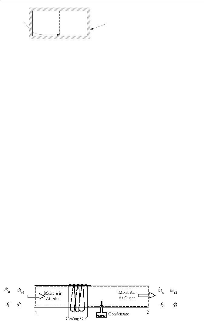
14. Moist air at 15 psia, 90 F, and a relative humidity of 60% enters a cooling duct
at a rate of 1200 ft
3
/m. Temperature of the saturated mixture at the exit of the
cooling coil is 65 F. Assuming negligible pressure drop, find the mass flow rate of
the condensate produced in the cooling duct.

IIc. Thermodynamics: Mixtures
220
15. Determine the amount of condensate, the final pressure, and heat transfer in the
cooldown process of a sample of moist air. The process takes place in a rigid con-
tainer having a volume of 35 m
3
. Moist air is initially at 1.5 bar, 120 C, and 10%.
The final temperature is 22 C. [Ans.: 3.15 kg].
16. Consider constant-volume cooldown of a mixture of water vapor and nitrogen
in a 17.66 ft
3
container. The mixture is originally at 122 F, 290 psia, and 40%
relative humidity. The mixture is cooled to 50 F. Find the heat transfer in this
process. [ =
CV
Q –321 Btu]
17. Find the relative humidity in a room at a temperature of 20 C. The wet bulb
temperature is 15.5 C.
[Ans.: 63%].
18. In Example IIc.4.2, we assumed that all of the incoming steam is condensed in
the quench tank. Find the final pressure assuming that 5% of the steam escapes
from the pool region to the vapor region.
19. A power plant uses a cooling tower as the heat sink. The net power produced
by the plant is 270 MWe. The plant thermal efficiency is 35%. Use these and
other pertinent data given below to find a) the mass flow rate of air and b) the mass
flow rate of make up water.
circulating water: inlet temperature T
wi
= 104 F (40 C) and exit temperature T
we
=
86 F (30 C)
air: inlet temperature T
ai
= 77 F (25 C), relative humidity
φ
ι
= 35%, air exit tem-
perature T
ae
= 95 F (35 C) and relative humidity
φ
e
= 90%
make-up water: inlet temperature T
mw
= 68 F (20 C).
[Ans.: for air: 57.83E6 lbm/h, for makeup water: 1.366E6 lbm/h].
20. A BWR containment design is suggested as shown in the Figure. The reactor
is isolated within a drywell compartment. A rupture disk caps the end of a duct
leading into a vapor suppression pool of water. The pool is inside a secondary
compartment. The rupture disk fails at a differential pressure of 60 psi (0.414
MPa). Now consider the case of a main steam line break. Use the following data
to find the time that the rupture disk fails.
Drywell: initial temperature T
i
= 100 F (38 C), initial pressure P
i
= 14.7 psia
(0.1013 MPa), initial relative humidity
φ
i
= 0%, and free volume V
drywell
= 5E5 ft
3
(14.16E3 m
3
).
Secondary-containment: initial pressure = 14.7 psia (0.1013 MPa), and free vol-
ume = 5E6 ft
3
(14.16E4 m
3
)
Suppression pool: water volume = 2.3E5 ft
3
(6.5E3 m
3
) and initial temperature =
100 F (38 C).
Steam blowdown: steam mass flow rate from the steam line to the drywell
m
=
500 lbm/s (227 kg/s) for the duration of t < 360 s and
m
= 500e
–t/
θ
lbm/s (227e
–t/
θ
kg/s ) for t ≥ 360 s and
θ
= 100 s. In order to avoid the necessity of an iterative so-
lution, use the following simplifying assumpions: