Martienssen W., Warlimont H. (Eds.). Handbook of Condensed Matter and Materials Data
Подождите немного. Документ загружается.

242 Part 3 Classes of Materials
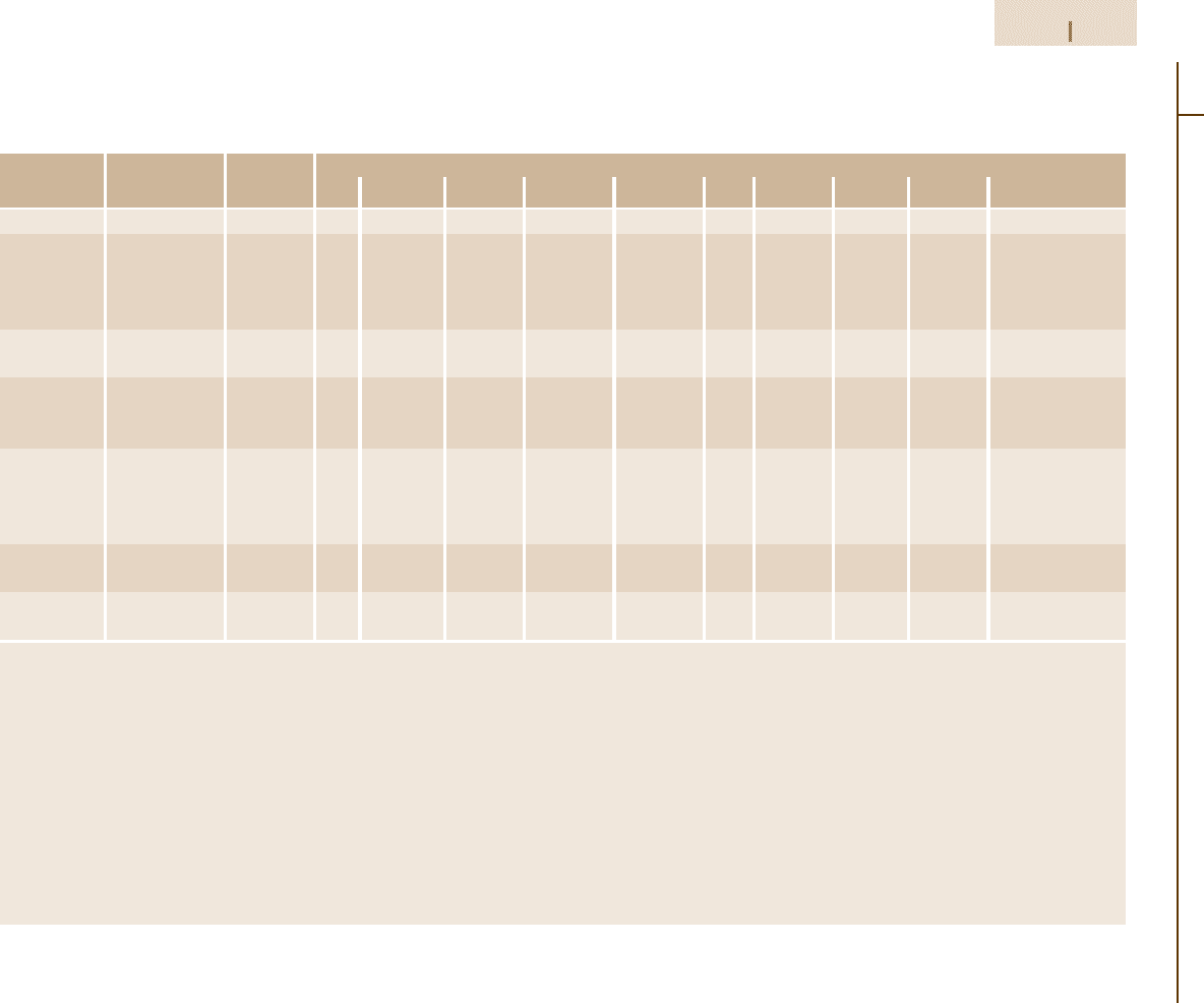
Table 3.1-46 Compositional limits of HSLA steel grades according to ASTM standards [1.80], cont.
ASTM speci- Type or UNS desig- Heat compositional limits (wt%)
b
fication
a
grade nation C Mn P S Si Cr Ni Cu V Other
A 690 – K12249 0.22 0.60–0.90 0.08–0.15 0.05 0.10 – 0.40–0.75 0.50 min – –
A 709 Grade 50, type 1 – 0.23 1.35 0.04 0.05 0.40 – – – – 0.005–0.05 Nb
Grade 50, type 2 – 0.23 1.35 0.04 0.05 0.40 – – – 0.01–0.15 –
Grade 50, type 3 – 0.23 1.35 0.04 0.05 0.40 – – –
h
0.05 Nb max
Grade 50, type 4 – 0.23 1.35 0.04 0.05 0.40 – – –
i
0.015 Nb max
A 715 – – 0.15 1.65 0.025 0.035 – – – – Added as Ti, Nb added
necessary as necessary
A 808 – – 0.12 1.65 0.04 0.05 max or 0.15–0.50 – – – 0.10 0.02–0.10 Nb,
V+Nb =0.15 max
0.010 max
A 812 65 – 0.23 1.40 0.035 0.04 0.15–0.50
j
– – – V + Nb = 0.05 Nb max
0.02–0.15
80 – 0.23 1.50 0.035 0.04 0.15–0.50 0.35 – – V + Nb = 0.05 Nb max
0.02–0.15
A 841 – – 0.20
k
0.030 0.030 0.15–0.50 0.25 0.25 0.35 0.06 0.08 Mo, 0.03 Nb,
0.02 Al total
A 871 – – 0.20 1.50 0.04 0.05 0.90 0.90 1.25 1.00 0.10 0.25 Mo, 0.15 Zr,
0.05 Nb, 0.05 Ti
a
For characteristics and intended uses, see Table 3.1-48; for mechanical properties, see Table 3.1-47.
b
If a single value is shown, it is a maximum unless otherwise stated.
c
Values may vary, or minimum value may exist, depending on product size and mill form.
d
Optional or when specified
e
May purchased as type 1 (0.005–0.05 Nb), type 2 (0.01–0.15 V), type 3 (0.05 Nb, max, plus 0.02–0.15 V) or type 4 (0.015 N, max, plus V ≥ 4N).
f
If chromium and silicon are each 0.50% min, the copper minimum does not apply.
g
May be substituted for all or part of V.
h
Niobium plus vanadium, 0.02 to 0.15%.
i
Nitrogen with vanadium content of 0.015% (max) with a minimum vanadium-to-nitrogen ratio of 4:1.
j
When silicon-killed steel is specified.
k
For plate under 40 mm (1.5in.), manganese contents are 0.70 to 1.35% or up to 1.60% if carbon equivalents do not exceed 0.47%.
For plate thicker than 40 mm (1 to 5 in.), ASTM A 841 specifies manganese contents of 1.00 to 1.60%
Part 3 1.5
Metals 1.5 Iron and Steels 243
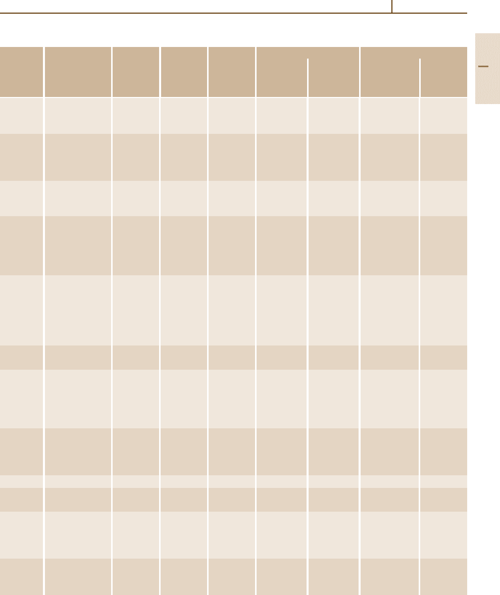
Table 3.1-47 Tensile properties of HSLA steel grades specified in ASTM standards [1.80]
ASTM Type, grade Product Minimum Minimum Minimum elongation (%)
c
Bend radius
c
speci- or condition thickness
b
tensile yield in 200 mm in 50 mm Longitudinal Transverse
fication
a
(mm) strength
c
strength
c
(MPa) (MPa)
A242 Type 1 20 480 345 18 – – –
20–40 460 315 18 21 – –
40–100 435 290 18 21 – –
A572 Grade 42 150 415 290 20 24
d
–
Grade 50 100 450 345 18 21
d
–
Grade 60 32 520 415 16 18
d
–
Grade 65 32 550 450 15 17
d
–
A588 Grades A–K 100 485 345 18 21
d
–
100–125 460 315 – 21
d
–
125–200 435 290 – 21
d
–
A606 Hot rolled sheet 480 345 – 22 t 2t −3t
Hot rolled sheet 450 310 – 22 t 2t −3t
and annealed
or normalized
Cold rolled sheet 450 310 – 22 t 2t −3t
A607 Grade 45 sheet 410 310 – 22–25 t 1.5t
Grade 50 sheet 450 345 – 20–22 t 1.5t
Grade 55 sheet 480 380 – 18–20 1.5t 2t
Grade 60 sheet 520 415 – 16–18 2t 3t
Grade 65 sheet 550 450 – 15–16 2.5t 3.5t
Grade 70 sheet 590 485 – 14 3t 4t
A618 Ia, Ib, II 19 485 345 19 22 t −2t –
Ia, Ib, II, III 19–38 460 315 18 22 t −2t –
A633 A 100 430–570 290 18 23
d
–
C, D 65 485–620 345 18 23
d
–
C, D 65–100 450–590 315 18 23
d
–
E 100 550–690 415 18 23
d
–
E 100–150 515–655 380 18 23
d
–
A656 50 50 415 345 20 –
d
–
60 40 485 415 17 –
d
–
70 25 550 485 14 –
d
–
80 20 620 550 12 –
d
–
A690 – 100 485 345 18 – 2t –
A709 50 100 450 345 18 21 – –
50W 100 450 345 18 21 – –
A715 Grade 50 sheet 415 345 – 22–24 0 t
Grade 60 sheet 485 415 – 20–22 0 t
Grade 70 sheet 550 485 – 18–20 t 1.5t
Grade 80 sheet 620 550 – 16–18 t 1.5t
A808 – 40 450 345 18 22 – –
40–50 450 315 18 22 – –
50–65 415 290 18 22 – –
Part 3 1.5
244 Part 3 Classes of Materials
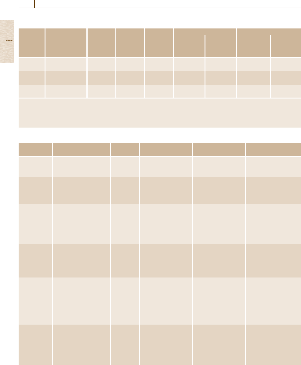
Table 3.1-47 Tensile properties of HSLA steel grades specified in ASTM standards [1.80], cont.
ASTM Type, grade Product Minimum Minimum Minimum elongation (%)
c
Bend radius
c
speci- or condition thickness
b
tensile yield in 200 mm in 50 mm Longitudinal Transverse
fication
a
(mm) strength
c
strength
c
(MPa) (MPa)
A812 65 sheet 585 450 – 13–15 – –
80 sheet 690 550 – 11–13 – –
A841 – 65 485–620 345 18 22 – –
65–100 450–585 310 18 22 – –
A871 60, as-hot-rolled 5–35 520 415 16 18 – –
65, as-hot-rolled 5–20 550 450 15 17 – –
a
For characteristics and intended uses, see Table 3.1-48; for specified composition limits, see Table 3.1-46
b
Maximum product thickness exept when a range is given. No thickness are specified for sheet products.
c
May vary with product size and mill form
d
Optional supplementary requierement given in ASTM A6
Table 3.1-48 Summary of characteristics and uses of HSLA steels according to ASTM standards [1.80]
ASTM Title Alloying Avalible mill forms Special Intended uses
specification
a
elements
b
characteristics
A 242 High-strength low-alloy Cr, Cu, N, Plate, bar, and shapes Atmospheric-corrosion Structural members
structural steel Ni, Si, Ti, ≤ 100 mm in thickness resistance four times in welded, bolted,
V, Z r of carbon steel or riveted construction
A 572 High-strength low-alloy Nb, V, N Plate, bar, and sheet Yield strength of Welded, bolted, or riveted
niobium-vanadium steels piling ≤ 150 mm 290 to 450 MPa in structures, but many
of structural quality in thickness six grades bolted or riveted
bridges and buildings
A 588 High-strength low-alloy Nb, V, Cr, Plate, bar, and shapes Atmospheric-corrosion Welded, bolted, or riveted
structural steel Ni, Mo, Cu, ≤ 200 mm in thickness resistance four times structures, but primarily
with 345 MPa minimum Si, Ti, Zr of carbon steel; welded bridges and
yield point ≤ 100 mm nine grades of buildings in which
in thickness similar stregth weight savings or added
durability is important
A 606 Steel sheet and strip Not Hot-rolled and Atmospheric-corrosion Structural and
hot-rolled steel and specified cold-rolled sheet and twice that of carbon miscellaneous purposes
cold-rolled, high-strength strip steel (type 2) or four for which weight savings
low-alloy with improved times of carbon steel or added durability
corrosion resistance (type 4) is important
A 607 Steel sheet and strip Nb, V, N, Hot-rolled and Atmospheric-corrosion Structural and
hot-rolled steel and Cu cold-rolled sheet and twice that of carbon miscellaneous purposes
cold-rolled, high-strength strip steel, but only when for which greater
low-alloy niobium copper content is strength or weight
and/or vanadium specified; yield savings is important
strength of 310 to
485 MPa in six grades
A 618 Hot formed welded and Nb, V, Si, Square, rectangular Three grades of similar General structural
seamless high-strength Cu round and special- yield strength; may be purposes include welded,
low-alloy structural shape structural purchased with bolted or riveted
tubing welded or seamless atmospheric-corrosion bridges and buildings
tubing resistance twice that
of carbon steel
Part 3 1.5
Metals 1.5 Iron and Steels 245
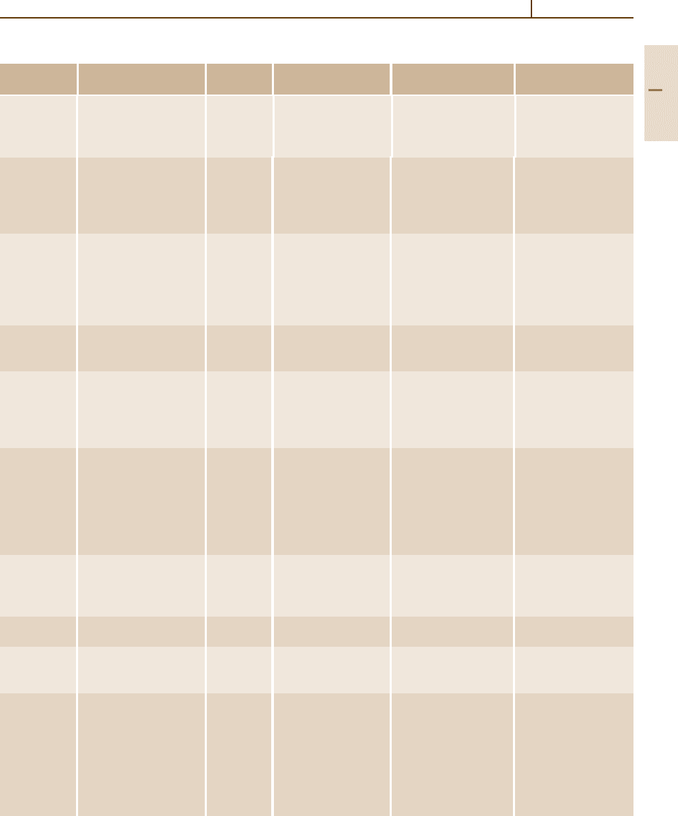
Table 3.1-48 Summary of characteristics and uses of HSLA steels according to ASTM standards [1.80], cont.
ASTM Title Alloying Avalible mill forms Special Intended uses
specification
a
elements
b
characteristics
A 633 Normalized high-strength Nb, V, Cr, Plate, bar, and shapes Enhanced notch Welded, bolted, or riveted
low-alloy structural steel Ni, Mo, Cu, ≤ 150 mm in thickness toughness; yield structures for service at
N, Si strength of 290 to temperatures at or above
415 MPa in five grades −45
◦
C
A 656 High strength low-alloy, V, A l , N , Plate, normally Yield strength of Truck frames, brackets,
hot rolled structural Ti, Si ≤ 16 mm in thickness 552 MPa crane booms, rail cars
vanadium-aluminium- and other applications
nitrogen and titanium- for witch weight savings
aluminium steels is important
A 690 High-strength low-alloy Ni, Cu, Si Structural-quality Corrosion resistance Dock walls, sea walls
steel H-piles and sheet H-pills and sheet piling two to three times Bulkheads, excavations
piling greater than that of and similar structures
carbon steel in the exposed to seawater
splash zone of marine
marine structures
A 709, grade Structural steel V, N b , N , All structural-shape Minimum yield strength Bridges
50 and 50W
Cr, Ni, Mo groups and plate of 345 MPa, Grade 50W
≤ 100 mm in thickness is a weathering steel
A 714 High-strength low-alloy V, N I , C r , Pipe with nominal Minimum yield strength Piping
welded and seamless Mo, Cu, pipe size diameters of ≤ 345 MPa and
steel pipe Nb of 13 to 660 mm corrosion resistance two
or four times that
of carbon steel
A 715 Steel sheet and strip Nb, V, Cr, Hot-rolled sheet Improved formability
c
Structural and
hot-rolled. high-strength Mo,N,Ti, and strip compared to a A 606 miscellaneous
low-alloy with improved Zr, B and A 607; yield applications for which
formability strength of 345 to high strength, weight
550 MPa in four grades savings, improved
formability and good
weldability are important
A 808 High-strength low-alloy V, N b Hot-rolled plate Charpy V-notch impact Railway tank cars
steel with improved ≤ 65 mm in thickness energies of 40–60 J
notch toughness (40–60 ft lfb)
at −45
◦
C
A 812 High-strength low-alloy V, N b Steel sheet in coil form Yield strength of Welded layered pressure
steels 450–550 MPa vesels
A 841 Plate produced by V, N b , C r Plates ≤ 100 mm Yield strength of Welded pressure vessels
themomechanical Mo, Ni in thickness 310–345 MPa
controlled processes
A 847 Cold formed welded and Cu, Cr, Ni, Welded rubing with Minimum yield strength Round, square, or
seamless high-strength Si, V, Ti, maximum periphery of ≤ 345 MPa with specially shaped
low-alloy structural Zr, Nb 1625 mm and wall atmosphieric-corrosion structural tubing
rubing with improved thickness of 16 mm or twice that of carbon for welded, riveted or
atmospheric corrosion seamless tubing with steel bolted construction
resistance maximum periphery of of bridges and buildings
810 mm and wall
thickness of 13 mm
Part 3 1.5
246 Part 3 Classes of Materials
Table 3.1-48 Summary of characteristics and uses of HSLA steels according to ASTM standards [1.80], cont.
ASTM Title Alloying Avalible mill forms Special Intended uses
specification
a
elements
b
characteristics
A 860 High-strength butt- Cu, Cr, Ni, Normalized or Minimum yield strength High-pressure gas
welding fittings of Mo, V, Nb, quenched-and- ≤ 485 MPa and oil transmission
wrought high-strength Ti tempered wrought lines
low-alloy steel fittings
A 871 High-strength low-alloy V, N b , T i As-rolled plate Atmosperic-corrosion Tubular structures and
steel with atmospheric Cu, Mo, Cr ≤ 35 mm in thickness resistance four times poles
corrosion resistance that of carbon
structural steel
a
For grades and mechanical properties, see Table 3.1-47.
b
In addition to carbon, manganese, phosphorus, and sulfur. A given grade may contain one or more of the listed elements, but not necessarily
all of them; for specified compositional limits, see Table 3.1-46.
c
Obtained by producing killed steel, made to fine grain practice, and with microalloying elements such as niobium, vanadium
titanium, and zirconium in the composition.
forming elements C, N, Ni, Mn, Cu, and Co. All alloying
elements suppress the austenite to martensite transfor-
mation by reducing the M
s
temperature, so that the steel
may remain fcc at and below room temperature at a suf-
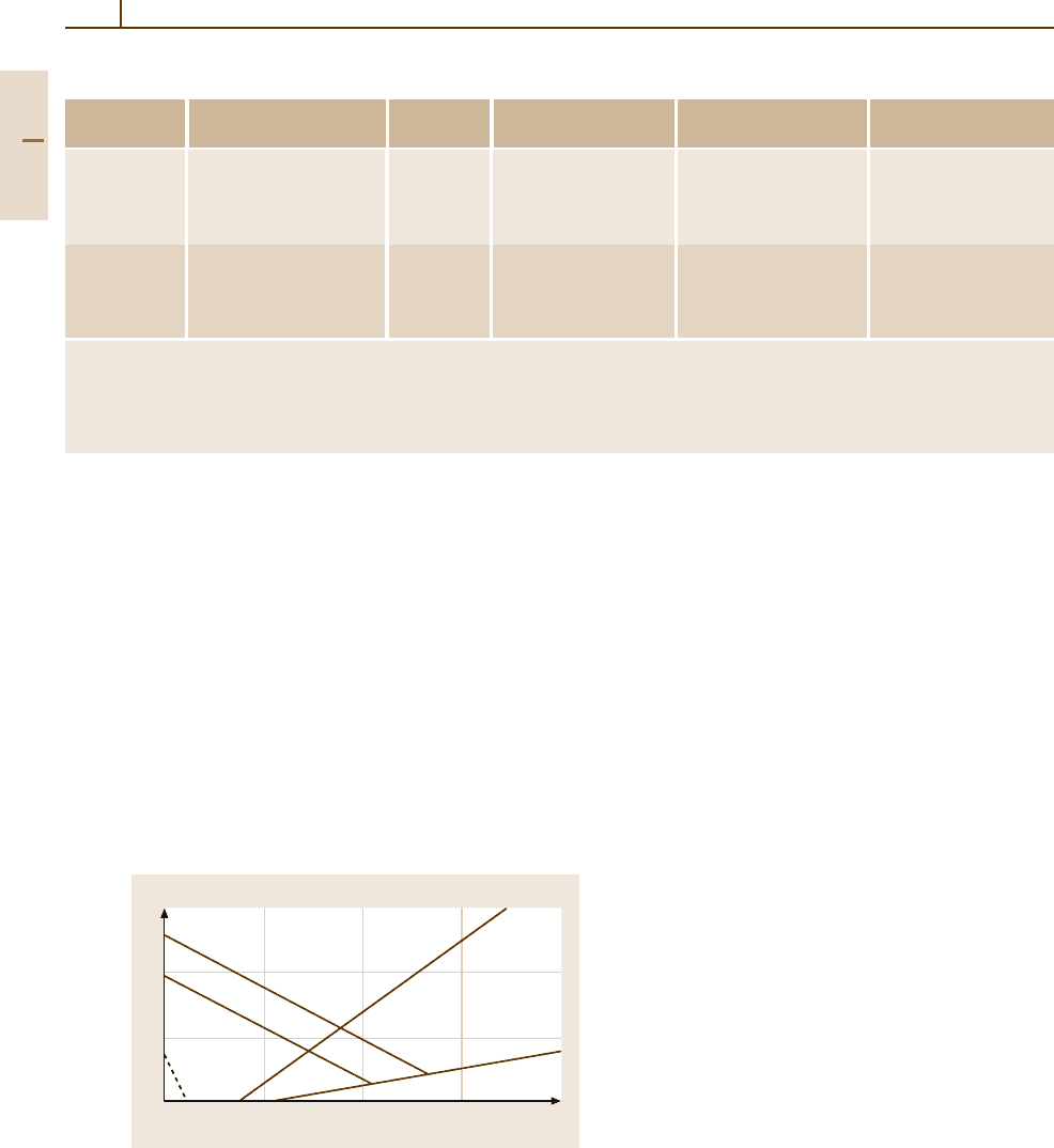
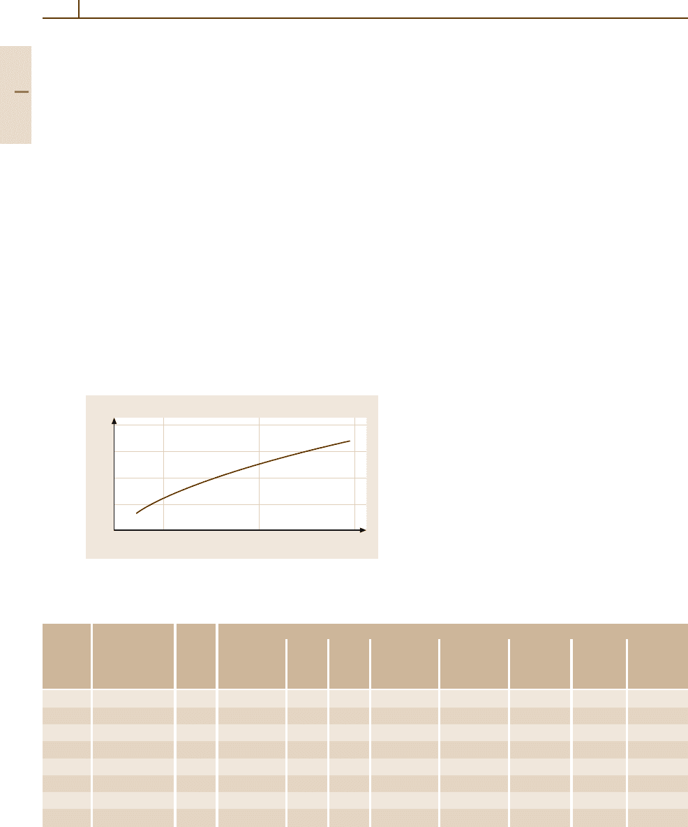
ficiently high alloy content. For a rough estimate of the
structural components of a stainless steel as a function
of alloy composition, the so-called Schaeffler diagram
(initially determined by M. Strauss and E. Maurer in
1920) can be used (see Fig. 3.1-114 [1.77]). It relates the
equivalent Cr and Ni content to the observed fractions
of martensite, austenite, and ferrite. One of the formu-
las of the Ni and Cr equivalent used most frequently is
that of Schneider [1.85] (in wt%):
Cr
equ
= Cr +2Si+1.5Mo+5V+5.5Al+1.5Ti
+0.7W
20
10
0
10 20 30
Nickel equivalence (wt %)
Chromium equivalence (wt %)
Austenite
A.+M.
Martensite
M.+F.
A.+M.+F.A.+M.+F.
A.+M.+F.
Austenite + Ferrite
Ferrite
Fig. 3.1-114 Structure of iron-based alloys as a function of
the concentrations of the chromium and nickel equivalent
elements. A: austenite (face centered cubic); F: ferrite (body
centered cubic); M: martensite (tetragonal-body centered
cubic) [1.77]
and
Ni
equ
= Ni +Co+0.5Mn+0.3Cu+25 N+30 C .
Ferritic Chromium Steels
High chromium (≥18 wt% Cr) and low carbon concen-
trations result in a fully ferritic structure of the steels at
all temperatures, i. e., with a bcc delta ferrite structure
and no phase transformations. Therefore these steels
cannot be strengthened by quenching and tempering.
The possibility to increase strength by cold deforma-
tion is limited since it decreases ductility and toughness.
Steels containing < 18 wt% Cr form some austenite dur-
ing heating which can be transformed into martensite
by fast cooling, thus strengthening the steel. A tem-
pering treatment just below Ar
1
results in a mixture of
δ-ferrite, α-ferrite, and carbides formed from tempered
martensite.
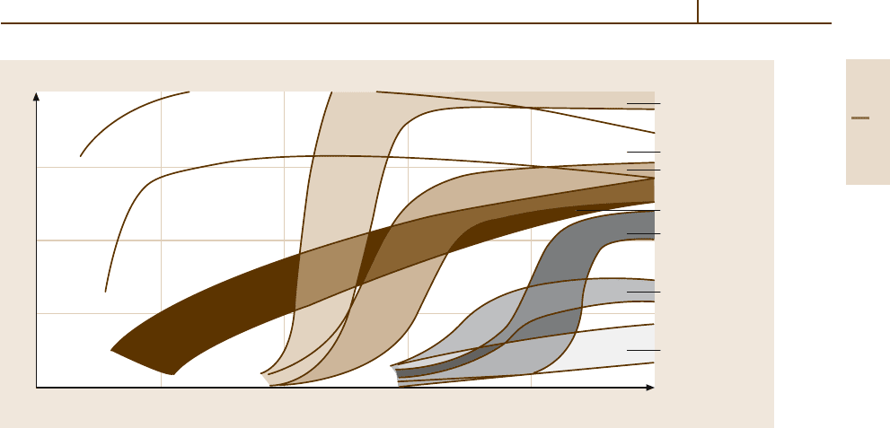
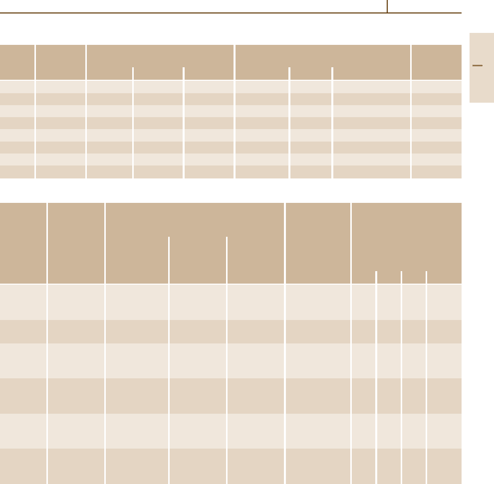
In general the toughness of the conventional stain-
less ferritic chromium steels is not very high, the impact
transition temperature often being at or above room
temperature and reaching 100
◦
C after welding (see
curve (e) in Fig. 3.1-115). This is due to (i) the ten-
dency of the ferritic stainless steels to pronounced grain
coarsing on heat treatments, leading to a relatively large
grain size (which cannot be refined by phase transfor-
mation) and (ii) the precipitation of chromium carbides
at the grain boundaries. Both effects render the steel
rather brittle after welding. Furthermore, precipitation
of chromium carbides at the grain boundaries causes
susceptibility to intergranular corrosion due to the for-
mation of zones with local chromium depletion along the
grain boundaries. Some improvement can be achieved
Part 3 1.5
Metals 1.5 Iron and Steels 247
200
150
100
50
0
–300 –200 –100 0 100 200
Test Temperature (°C)
Cr-Superferrite
CrNi-Austenite
CrNi-Superferrite
CrNi-Martensite
Cr-Ferrite
13 Cr-Martensite
17 Cr-Martensite
Notched bar impact (J)
Fig. 3.1-115 Notched bar impact energy as a function of test temperature of various types of stainless steels (DVM
samples: dimension 10 × 10× 55 mm
3
, notch depth 3 mm, notch root radius 1 mm)
(i) by quenching or a suitable diffusion heat treatment
for equilibration of the chromium distribution, and (ii)
by a stabilization of the steels with small amounts of Ti
and/or Nb which are added to bind the carbon and nitro-
gen in more stable compounds. In unstabilized steels the
carbon content is generally restricted to ≤ 0.1 wt%. Up
to 2 wt% Mo improves the corrosion resistance of fer-
ritic chromium steels, especially in chloride-containing
media.
In Table 3.1-49 the chemical composition of a num-
ber of ferritic stainless steels is given. The most
common representative is the grade X6Cr17/AISI 430.
Table 3.1-50 presents some information on hot defor-
mation and recommended heat treatment parameters.
Tables 3.1-51 and 3.1-52 show typical data of the
mechanical and physical properties, respectively, and
Table 3.1-53 reviews the weldability of these steels.
Good ductility and toughness at sub-zero tem-
peratures can be achieved when the carbon and
nitrogen content in ferritic steels is reduced to very
low concentrations (below 100 ppm) (see curve (a) in
Fig. 3.1-115). With higher alloy concentrations on the
orderof26–30wt%Cr,upto2wt%Mo,andupto
4 wt% Ni, these so-called superferritic steels exhibit ex-
cellent corrosion properties, i. e., high resistance against
transcrystalline stress corrosion cracking and chloride-
induced pitting corrosion, as well as intercrystalline and
general corrosion. However, in order to maintain the
low C and N contents even after welding, an effective
inert gas shielding is required during welding as it is
known for welding of Ti. Obviously, the high purity
requirements which have to be observed during melt-
ing, hot forming and welding, and some embrittling
effects which occur in high Cr steels after lengthy high
temperature exposure (475
◦
embrittlement and σ-phase
formation) have precluded as yet a wider application
of these steels, in spite of their attractive properties. In
addition to their good corrosion resistance these steels
possess a higher thermal conductivity than austenitic
stainless steels, which is of special interest in heat ex-
changer applications, and a lower rate of work hardening
on cold deformation.
Part 3 1.5
248 Part 3 Classes of Materials
Table 3.1-49 Chemical composition of ferritic stainless steels
Grade no. Steel designation ASTM Chemical composition (wt%)
(EN 10088)
A 276/ C Si Mn S P Cr Mo Others
AISI
grade
1.4016 X6Cr17 430 ≤0.08 ≤1 ≤1 ≤0.03 15.5–17.5
1.4104 X12CrMoS17 430F 0.10–0.17 ≤1.5 ≤1 0.15–0.35 ≤0.06 15.5–17.5 0.2–0.6
1.4105 X4CrMoS18 ≤0.06 ≤1.5 ≤1 0.15–0.35 ≤0.06 16.5–18.5 0.2–0.6
1.4509 X2CrTiNb18 441 ≤0.03 ≤1 ≤1 ≤0.015 17.5–18.5 Ti 0.1–0.6
Nb 9x%C+
0.3–1.0
1.4510 X3CrTi17 430Ti ≤0.08 ≤1 ≤1 ≤0.03 ≤0.045 16–18 Ti ≥7x%C
up to 1.20%
1.4511 X3CrNb17 ≤0.08 ≤1 ≤1 ≤0.03 ≤0.045 16–18 Nb ≥ 12x%C
up to 1.20%
1.4113 X6Cr Mo17-1 434 ≤0.08 ≤1 ≤1 ≤0.03 ≤0.045 16–18 0.9–1.3
1.4520 X2CrTi15 ≤0.015 ≤0.5 ≤0.5 ≤0.020 ≤0.025 14–16 Ti 0.25–0.40
1.4521 X2CrMoTi18-2 444 ≤0.025 ≤1 ≤1 ≤0.03 ≤0.045 17–19 1.8–2.3 Ti ≥ 7x%(C+N)
up to 0.8,
(C+N) ≤ 0.04
X20Cr20 442 ≤0.2 ≤1 ≤1 ≤0.03 ≤0.04 18–23
1.3810 X20Cr25 446 ≤0.25 ≤0.5–2.0 ≤0.5 ≤0.03 ≤0.04 23–27
a
X1CrMo26-1 0.002 0.1 0.3 0.015 0.01 26 1 N 0.006
a
X1CrMo29-4 0.003 0.1 0.04 0.01 0.01 29.5 4
a
X1CrMoNi29-4-2 0.002 0.1 0.1 0.01 0.01 29.5 4 Ni 2.2
a
X2CrMoNiTi25-4-4 0.012 0.04 0.3 0.006 25 4 Ni 4, Ti 0.4
a
Typical values
Table 3.1-50 Heat treatment conditions of ferritic stainless steels
Grade no. Rolling and forging (
◦
C) Soft annealing
Temperature (
◦
C) Time (min) Cooling
1.4016 1100–800 750–850 20–30 Air/water
1.4104 1100–800 750–850 120–180 Air/furnace
1.4105 1100–800 750–850 Air/water
1.4510 1100–800 750–850 20–30 Air/water
1.4511 1050–750 750–850 20–30 Air/water
1.4113 1050–750 750–850 20–30 Air/water
1.4521 1150–750 750–900 Air/water
X1CrMo26-1 1150–750 750–900 Air/water
X1CrMo29-4 1100–800 750–800 120–360 Air/furnace
X1CrMoNi29-4-2 1150–750 750–800 15–30 Air
X2CrMoNiTi25-4-4 1100–800 730–780 120–360 Air/furnace
Part 3 1.5
Metals 1.5 Iron and Steels 249
Table 3.1-51 Mechanical properties of ferritic stainless steels
Grade no. Heat treatment Tensile properties of flat products ≤ 25 mm in thickness
condition
Min. yield strength Ultimate tensile Min. fracture
or 0.2% proof strength (MPa) strength (MPa) elongation A
5
(%)
1.4016 Annealed 270 450–600 20
1.4104 Annealed 300 540–740 16
1.4105 Annealed 270 450–650 20
1.4510 Annealed 270 450–600 20
1.4511 Annealed 250 450–600 20
1.4113 Annealed 260 480–630 20
1.4521 Annealed 320 450–650 20
X1CrMo26-1 Annealed 275
a
450
a
22
a
X1CrMo29-4 Annealed 415
a
550
a
20
a
X1CrMoNi29-4-2 Annealed 415
a
550
a
20
a
X2CrMoNiTi25-4-4 Annealed 550
a
650
a
20
a
a
Typical values
Table 3.1-52 Physical properties of ferritic stainless steels
Grade no. Mean thermal expansion Density Thermal Specific heat Electrical Modulus of Magne-
coefficient between 20
◦
C (kg/dm
3
) conductivity at 20
◦
C resistvity elasticity tizable
and T (
◦
C) in 10
−6
K
−1
at 20
◦
C at 20
◦
C
100 200 300 400 (W/Km) (J/g K) ( mm
2
/m) (kN/mm
2
)
1.4016 10.0 10.0 10.5 10.5 7.7 25 0.46 0.60 220 yes
1.4104 10.0 10.5 10.5 10.5 7.7 25 0.46 0.70 216 yes
1.4105 10.0 10.5 10.5 10.5 7.7 25 0.46 0.70 216 yes
1.4510 10.0 10.0 10.5 10.5 7.7 25 0.46 0.60 220 yes
1.4511 10.0 10.0 10.5 10.5 7.7 25 0.46 0.60 220 yes
1.4113 10.0 10.0 10.5 10.5 7.7 25 0.46 0.70 216 yes
1.4521 10.4 10.8 11.2 11.6 7.7 15 0.43 0.80 220 yes
Table 3.1-53 Weldability of ferritic stainless steels
Grade no. Weldable Welding method Preheating After-treatment
SAW/MIG/TIG Arc Resistance Autogenous (
◦
C) Annealing at T (
◦
C)
welding welding welding welding
1.4016 Ye s + + + (+) 200 (+) 700
1.4104 No − − − − − − −
1.4105 No − − − − − − −
1.4510 Ye s + + + − 200 (+) 750
1.4511 Ye s + + + − 200 (+) 750
1.4113 Ye s + + − − − + 750
1.4521 Ye s + − − − − − −
X2CrMoTi29-4 Yes + − − −
X1CrMo26-1 Ye s + − − −
X1CrMo29-4 Ye s + − − −
X1CrMoNi29-4-2 Ye s + − − −
Part 3 1.5
250 Part 3 Classes of Materials
Martensitic and Martensitic-Ferritic
Chromium Steels
Steels with 11.5to18wt%Crandupto1.2 wt% C
are austenitic at high temperatures and can be trans-
formed into martensite by fast cooling. Due to the
high chromium content, the hardenability of these steels
is relatively high, so a fully martensitic transforma-
tion can be achieved even with relatively large cross
sections and moderate cooling rates. They are nor-
mally used for applications requiring a combination
of high hardness with good corrosion and wear resis-
tance. With carbon contents below about 0.35 wt% C
the steels are hypo-eutectic, and some ferrite will be
present after heat treatment. They can be austenitized
at ≥ 960
◦
C. Steels with ≥ 0.40 wt% C and 13 wt% Cr
are already hyper-eutectic and will contain some undis-
solved primary carbides after quenching. To dissolve
more carbon, these steels are usually quenched from
a higher austenitization temperature around 1050
◦
C.
The steels cannot be hardened if the carbon concen-
tration is below 0.12 wt% C and the chromium content
≥ 16 wt% Cr.
700
600
500
400
300
0.1 0.2 0.3
Carbon (wt %)
Hardness (HV)
Fig. 3.1-116 As-quenched hardness as a function of the
carbon content of a martensitic 12 wt% Cr steel
Table 3.1-54 Chemical composition of martensitic and martensitic-ferritic chromium steels
Grade Steel ASTM Chemical composition (wt%)
no. (EN designation A 276/ C Si Mn P S Cr Mo Ni
10088) AISI
grade
1.4006 X12Cr13 410 0.08–0.12 ≤1.0 ≤1.0 ≤0.045 ≤0.030 12.0–14.0 – –
1.4005 X12CrS13 416 ≤0.15 ≤1.0 ≤1.0 0.15–0.25 ≤0.045 12.0–13.0 – –
1.4021 X20Cr13 420 0.17–0.25 ≤1.0 ≤1.0 ≤0.045 ≤0.030 12.0–14.0 – –
1.4028 X30Cr13 420 0.28–0.35 ≤1.0 ≤1.0 ≤0.045 ≤0.030 12.0–14.0 – –
1.4104 X12CrMoS17-2 430F 0.10–0.17 ≤1.0 ≤1.5 ≤0.060 0.15–0.35 15.5–17.5 0.2–0.6
1.4057 X20CrNi17-2 431 0.14–0.23 ≤1.0 ≤1.0 ≤0.045 ≤0.030 15.5–17.5 – 1.50–2.50
1.4109 X70CrMo15 440A 0.60–0.75 ≤1.0 ≤1.0 ≤0.045 ≤0.030 13.0–15.0 0.50–0.60 –
1.4125 X10⁵CrMo17 440C 0.95–1.20 ≤1.0 ≤1.0 ≤0.045 ≤0.030 16.0–18.0 0.40–0.80
In some grades a small content of 0.5–1wt%Mo
(and sometimes some W, V, or Nb) is used to increase the
tempering resistance, i. e., to retain higher hardness on
tempering by means of precipitation reactions. Increased
S contents or Se additions improve the machinabil-
ity of the steels. About 1–2.5 wt% Ni together with
reduced carbon content is applied if hardenabilty of
higher cross sections and an improved weldability are
required.
The hardness after quenching depends on the carbon
content, as illustrated in Fig. 3.1-116 for a 12 wt% Cr
steel [1.77]. In the as-quenched state the steels are hard
but very brittle. Thus a tempering treatment is necessary
to adjust toughness and strength to the level required
for a specific application. For high hardness, annealing
temperatures of about 100–300
◦
C are applied, whereas
increases in ductility and toughness require tempering
at or above 650
◦
C.
The chemical composition for a number of marten-
sitic Cr steels is given in Table 3.1-54. Tables
3.1-55 – 3.1-58 review data on recommended heat
treatment conditions, mechanical properties, physical
properties, and weldability, respectively.
It should be noted that a different way to produce
stainless steels with high hardness is by precipitation
hardening. Such steels have a low carbon content and
contain in addition to chromium a few wt% of Ni and
Cu. The hardening is caused by Cu precipitates. Others
use precipitation hardening by intermetallic phases such
as NiTi, TiAl, or NiAl.
Part 3 1.5
Metals 1.5 Iron and Steels 251
Table 3.1-55 Heat treatment conditions of martensitic and martensitic-ferritic chromium steels
Grade Rolling Soft annealing Quenching Annealing
no.
and forging
T (
◦
C) T (
◦
C) Time (min) Cooling T (
◦
C) Medium Hardness HRC ca. T (
◦
C)
1.4006 1100–800 750–800 120–360 Air/furnace 950–1000 Air/oil 31 780–680
1.4005 1150–750 750–800 15–30 Air 950–1000 Oil 31 700–600
1.4021 1100–800 730–780 120–360 Air/furnace 980–1030 Air/oil 47 750–650
1.4028 1100–800 730–780 Air/furnace 980–1030 Air/oil 740–640
1.4104 1100–800 750–850 120–180 Air/furnace 980–1030 Air/oil 27 650–550
1.4057 1100–800 650–750 180–240 Air/furnace 980–1030 Air/oil 47 720–620
1.4109 1100–900 790–840 120–360 Furnace 1020–1060 Oil 59 200–150
1.4125 1100–900 800–850 160–240 Furnace 1000–1050 Oil 61 300–100
Table 3.1-56 Mechanical properties of martensitic and martensitic-ferritic chromium steels
Grade no. Heat Tensile properties of CVN impact Min. yield strength or
treatment flat products ≤25 mm thickness energy at room 0.2% proof strength
condition temperature (J) at T (
◦
C) in MPa
Min. yield Ultimate Fracture longitudinal/
strength or tensile elongation transversal
0.2% proof strength A
5
(%)
strength (MPa) (MPa) long./transv. 100 200 300 400
1.4006 Annealed 250 450–650 20/15 −/− 235 225 220 195
Quenched 420 600–800 16/12 −/− 420 400 365 305
and tempered
1.4005 Quenched 440 590–780 12/− −/− − − − −
and tempered
1.4021 Annealed − ≤740 − −/−
Quenched 450 650–800 15/11 30/− 420 400 365 305
and tempered 550 750–950 13/10 25/−
1.4028 Annealed − ≤780 − −/−
Quenched
and tempered 600 800–1000 − 11/−
1.4104 Annealed 300 540–740 − −/−
Quenched
and tempered 450 640–840 − −/−
1.4057 Annealed − ≤950 − −/−
Quenched
and tempered 550 750–950 14/10 20/− 495 460 430 345
Part 3 1.5