Martienssen W., Warlimont H. (Eds.). Handbook of Condensed Matter and Materials Data
Подождите немного. Документ загружается.

222 Part 3 Classes of Materials
3.1.5.1 Phase Relations
and Phase Transformations
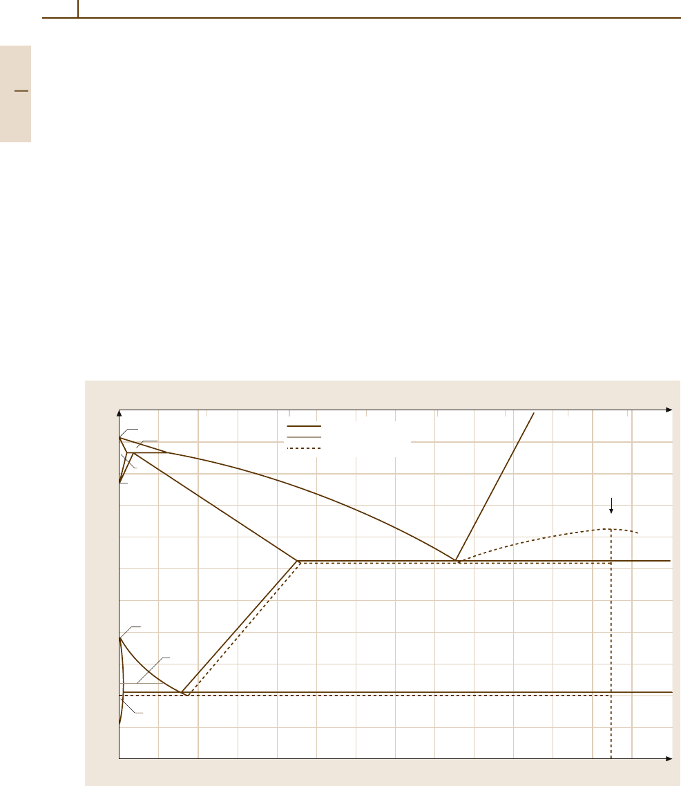
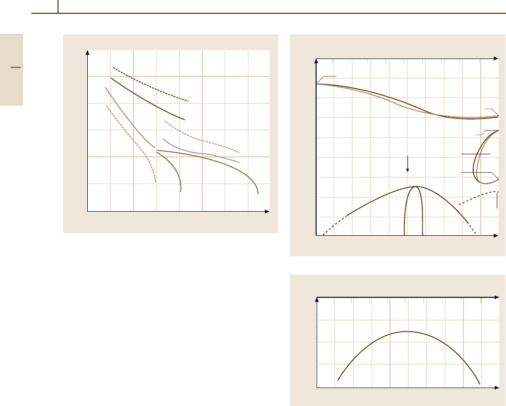
Iron–Carbon Alloys
The most frequent alloying element of iron is car-
bon. The Fe
−
C phase diagram (Fig. 3.1-99) shows
the important metastable phase equilibria involving the
metastable carbide Fe
3
C, called cementite, in dashed
lines, whereas the stable equlibria with graphite C are
shown in solid lines. The formation of Fe
3
C predom-
inates in most carbon and low-alloy steels because
the activation energy of its nucleation is consider-
ably lower than that of graphite. At higher carbon
contents (2.5–4.0 wt% C) and in the presence of Si
(1.0–3.0 wt% Si), graphite formation is favored. This
is the basis of alloying and microstructure of gray cast
iron (see Sect. 3.1.5.7).
The Fe
−
C phase forms interstitial solid solutions
of α-andγ -Fe. The solid solution phase of α-Fe is
called ferrite, the solid solution phase based on γ -Fe
is called austenite in the binary Fe
−
C system. These
1900
1800
1700
1600
1500
1400
1300
1200
1100
1000
900
800
1234
5
67
Fe 2 4 6 8 10 12 14 16 18 20 22 24 26 28
T(K) C(wt %)
C(at. %)
Fe–C
1809 K
1766 K
1665 K
2.43
1184 K
1043 K
3.12 3.43
9.06
9.23
1009 K
1000 K
1426 K
1420 K 17.1 17.3
1525 K
L + (C)
Fe
3
C
Stable
Metastable
Curie temperature
δ
γ
α
Fig. 3.1-99 Fe
−
C phase diagram. Metastable equilibria involving cementite Fe
3
Careshownindashed lines,stable
equilibria with graphite C are shown in solid lines [1.82] (dotted lines – Curie temperature)
terms for the solid solutions phases of α-andγ -Fe
are applied to all other Fe-based alloy systems as
well. Since phase transformations induced by cooling
from the austenite phase field play a major role to in-
duce particular microstructures and properties, some
resulting microstructures have also been given partic-
ular terms and form the basis of the nomenclature
in steels. Cooling of Fe
−
C alloys from the austenite
phase field can lead to three different phase transfor-
mations below the eutectoid temperature of 1009 K
(736
◦
C). Their kinetics of formation depends on com-
position and cooling rate. The transformation products
are:
•
Pearlite, a lamellar product of ferrite and cementite.
It is formed by a discontinuous (pearlitic) trans-
formation, i. e., both phases are formed side by
side in the reaction front. The lamellar spacing de-
creases with decreasing temperature of formation.
The maximum rate of formation occurs at about
500
◦
C.
Part 3 1.5
Metals 1.5 Iron and Steels 223
•
Bainite, a plate- or spearhead-shaped product con-
sisting of a ferrite matrix in which carbide particles
are dispersed. The bainitic transformation mechan-
ism depends sensitivelyon alloy composition and the
temperature of transformation, yielding essentially
two microstructural variants. A somewhat coarser
transformation product formed at about 450
◦
Cis
called upper bainite and a finer transformation
product formed at about 350
◦
C is termed lower
bainite.
•
Martensite, a plate-shaped product formed by
a diffusionless, athermal transformation. Thermo-
dynamically it is a metastable ferrite, designated
as α
and supersatured in carbon. But by the
displacive mechanism of the transformation, the dis-
tribution of the C atoms in the martensite lattice is
anisotropic such that is has a body-centered tetrag-
onal crystal structure and its c and a parameters
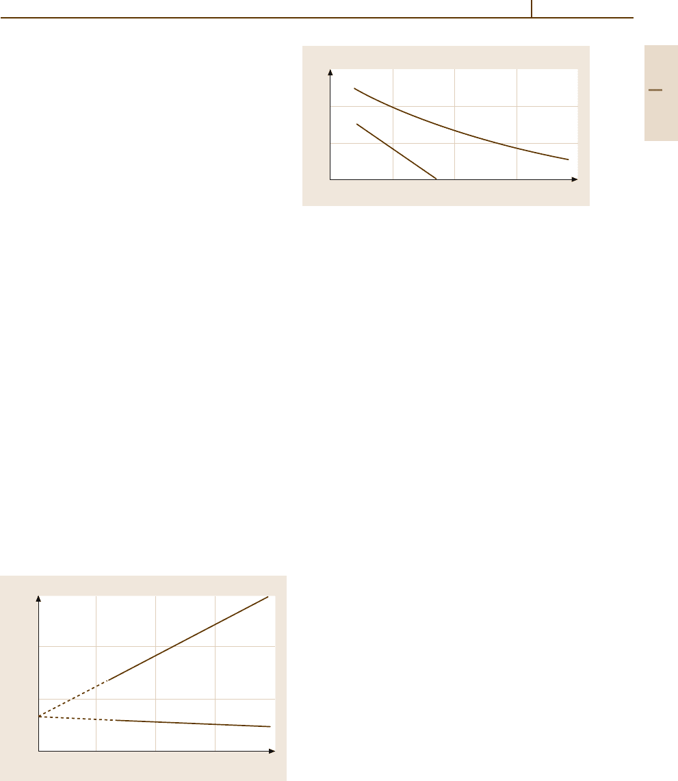
vary with the C content accordingly (Fig. 3.1-100).
The temperature below which martensite begins
to form upon queching is termed martensite
start temperature M
s
and depends strongly on
the C concentration (Fig. 3.1-101). M
f
designates
the temperature at which the transformation is
complete. In order to promote the diffusionless
martensitic transformation, the diffusion-dependent
transformations to pearlite and bainite have to
be suppressed by rapid cooling, usually termed
quenching.
Since martensite formation is used as a main hard-
ening mechanism in steels, the hardenability is a main
concern of alloy design and consequence of alloy
composition. The lower the rate of formation of the
0.310
0.300
0.290
0.280
Fe 2 4 6 8
C (at.%)
a, c (nm)
Fe–C
Martensite
T = 298 K
c
a
Fig. 3.1-100 Lattice parameters of Fe
−
C martensite as
a function of composition [1.82]
600
400
200
0
0 0.4 0.8 1.2 1.6
C content (wt %)
Transformation temperature (°C)
M
s
M
f
Fig. 3.1-101 Concentration dependence of the marten-
site transformation temperatures. M
s
– martensite start;
M
f
– martensite finish, i. e., austenite is transformed
completely
diffusion-dependent transformations, the higher is the
fraction of martensite formed upon cooling from the
austenite range, i. e.,the hardenability (see Sect. 3.1.5.2).
The rates of pearlite and bainite formation are reduced
by alloying with carbon and all substitutional alloy-
ing elements except by Co. But the decrease of M
s
with increasing alloy content has, also, to be taken into
account.
Subsequent heat treatment of the phases formed is
termed annealing with regard to ferrite and bainite, and
tempering with regard to martensite. These heat treat-
ments play a major role in optimizing the microstructure
to obtain specific properties. Upon subsequent heat treat-
ment the transformation products listed above undergo
the following reactions:
•
Pearlite is coarsened by the transition of the cemen-
tite lamellae into spherical particles, thus reducing
the interfacial free energy per unit volume. The
process is called spheroidization and consequently
the resulting microstructural constituent is termed
spheroidite.
•
Bainite is coarsened as well both by recovery of
the ferrite plates and by coarsening of the carbide
particles.
•
Martensite is essentially transformed into bcc fer-
rite by the precipitation of carbide particles during
tempering. The tempering treatment usually leads
to the precipitation of metastable carbides from
the martensite phase. Different metastable carbides
may be formed depending on alloy composition
(including substitutional alloying elements), tem-
perature, and time of annealing. A compilation of all
metastable carbides occurring in Fe
−
C(
−
X) alloys
is given in Table 3.1-40.
Part 3 1.5
224 Part 3 Classes of Materials
Table 3.1-40 Metastable and stable carbide phases occurring in the Fe
−
C(
−
X) alloy system [1.82]
Phase Structure Type a (nm) b (nm) c (nm)
Fe
4
C cub 0.3878
Fe
3
C orth Fe
3
C 0.50889 0.67433 0.452353
ε-Fe
3
C hex 0.273 0.433
Fe
2−3
C hex 0.4767 0.4354
Fe
5
C
2
mon Mn
5
C
2
1.1563 0.4573 0.5058
β =97.73
◦
Fe
7
C
3
hex Th
7
Fe
3
0.6882 0.4540
Fe
20
C
9
orth 0.9061 1.5695 0.7937
Heat Treatments
The heat treatments referred to above need to be spec-
ified rather succinctly such that they can be correlated
with the ensuing microstructures and properties. Fur-
thermore, the specifications of heat treatments require
taking the cross section and form of the part to be
heat treated into account (at least if the cross sections
get larger than, say, 0.5 mm). The finite thermal con-
ductivity and the heat capacity of the material will
cause any temperature change applied to the surface
to occur at a decreasing rate with increasing depth
in the heat-treated part. Thus, not only the time and
temperature of an isothermal treatment but also the
rate of cooling or the rate of heating are common
parameters to be specified. Beyond those referred to
above, the following treatments are widely applied to
steels:
Austenitizing. Heating to and holding in the range of
the austenite phase is commonly the first stage of trans-
formation heat treatments. The higher the austenitizing
temperature, the more lattice defects such as dislocations
and grain boundariesare annihilated. This lowers the rate
of nucleation of subsequent phase transformations.
Soft Annealing. This term is used for heat treatment
of hardenable steels containing ≥ 0.4 wt% C at tem-
peratures closely below the eutectoid temperature for
a duration of ≤ 100 h. It results in a microstructure of
coarse grained, ductile ferrite, and coarsened cementite.
Normalizing. This heat treatment is applied to obtain
a uniform, fine-grained microstructure. The first step
consists of heating the metal rapidly to, and holding it
at a temperature 30–50 K above the (α +γ)/γ phase
boundary (also referred to as the A
c3
line) for hypo-
eutectoid steels, and heating rapidly to and holding at
about 50 K above the eutectoid temperature (also re-
ferred to as A
c1
line). This step results in the formation of
a fairly fine-grained austenite and ferrite structure in the
hypo-eutectoid and in a fine-grained austenite with coag-
ulated grain boundary cementite in the hyper-eutectoid
compositions. Upon cooling, the austenite transforms
into pearlite and this microstructural state has a favorable
combination of strength, ductility, and machinability.
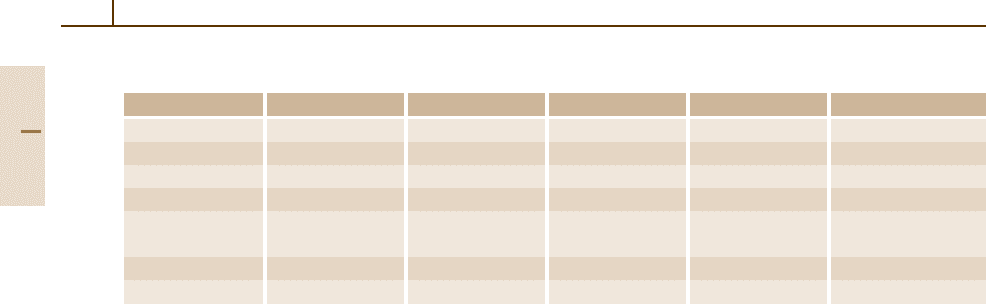
Substitutional Iron-Based Alloys
For the phase diagrams with substitutional alloying
components shown in later sections, a major aspect per-
taining to both the binary alloys shown and the steels
alloyed with these components is whether the α or the
γ phase of Fe is stabilized. i. e., which phase field is
expanded or contracted upon alloying.
Fe
−
Ni. Figure 3.1-102 shows the Fe
−
Ni phase equi-
libria indicating that Ni stabilizes the fcc γ phase. If
Fe-rich alloys are quenched from the γ phase field they
transform martensitically to bccα
martensite. The trans-
formation temperatures are shown in Fig. 3.1-103. The
Fe
−
Ni phase diagramis particularly relevant for the con-
trolled thermal expansion and constant-modulus alloys
as well as for the soft magnetic Fe
−
Ni based materials at
higher Ni contents. These, in turn, derive their magnetic
properties in part from the occurrence of the superlattice
phase FeNi
3
.
Nickel is added to Fe
−
C alloys to increase the hard-
enability and to increase the yield strength of ferrite by
solid solution hardening.
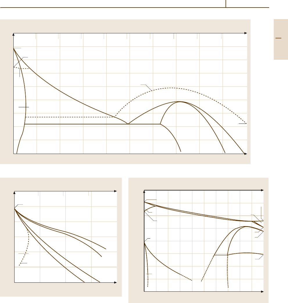
Fe
−
Mn. Figure 3.1-104 shows the Fe
−
Mn phase equi-
libria indicating that Mn is stabilizing the fcc γ phase
similar to Ni. It should be noted that quenching Fe-
rich alloys from the γ -phase field leads to two different
martensitic transformations which may result in a bcc
structure (α
martensite) or an hcp structure (ε
marten-
site). The transformation temperatures are shown in
Fig. 3.1-105. The martensitic transformation can also
be induced by deformation. This property is exploited
Part 3 1.5
Metals 1.5 Iron and Steels 225
1300
1200
1100
1000
900
800
700
600
500
400
10 20 30 40 50 60 70 80 90
Ni (wt %)
Fe 10 20 30 40 50 60 70 80 90
Ni (at.%)
Fe–Ni
1195 K
1043 K
T
C
( –Fe)
4.7
620 K
49 63
T
C
790 K
627 K
FeNi
3
α
( – Fe, Ni)
γ
Fig. 3.1-102 Fe
−
Ni phase diagram. T
C
– Curie temperature [1.82]
1400
1200
1000
800
600
400
200
Fe 10 20 30 40
10 20 30
T(K) Ni (wt %)
Ni (at.%)
Fe–Ni
1185 K
A
f
A
s
M
s
M
f
Martensite
( –Fe)
α
( –Fe, Ni)
γ
Fig. 3.1-103 Martensitic transformation temperatures of
Fe-rich Fe
−
Ni alloys. The reverse transformation is char-
acterized by the A
s
(austenite start) and A
f
(austenite finish)
temperatures [1.82]
2000
1800
1600
1400
1200
1000
800
600
400
10 20 30 40 50 60 70 80 90
Fe 10 20 30 40 50 60 70 80 90
Mn (at.%)
T(K)
Fe–Mn
1811 K
1667 K
1185 K
( –Fe)
δ
( –Fe)
α
( –Fe, –Mn)
γγ
( –Mn)
β
( –Mn)
α
( –Mn)
δ
1519 K
1352 K
1416 K
983 K
Mn (wt%)
Fig. 3.1-104 Fe
−
Mn phase diagram [1.82]
Part 3 1.5
226 Part 3 Classes of Materials
1200
1000
800
600
400
200
0
Fe 4 8 12 16 20 24 28 32
Mn (at.%)
T(K)
Fe– Mn
M
f
γ
→
α
'
M
s
γ
→
α
'
A
f
α
'
→
γ
A
s
α
'
→
γ
A
f
ε
→
γ
A
s
ε
→
γ
M
s
ε
→
α
'
M
s
γ
→
ε
Fig. 3.1-105 Martensitic transformation temperatures of
Fe-rich Fe
−
Mn alloys. The superscripts indicate the trans-
forming phases [1.82]
in the design of wear-resistant steels (Hatfield steel:
12 wt% Mn, 1 wt% C).
Manganese is contained in practically all commer-
cial steels because it is used for deoxidation of the
melt. Typical contents are 0.3–0.9 wt% Mn. Manganese
increases the hardenability of steels and contributes
moderately to the yield strength by solid solution
hardening.
Fe
−
Cr. The Fe
−
Cr phase diagram, Fig. 3.1-106, is the
prototype of the case of an iron-based system with an
α-phase stabilizing component. Chromium is the most
important alloying element of corrosion resistant, fer-
ritic stainless steels and ferritic heat-resistant steels.
If α-Fe
−
Cr alloys are quenched from above 1105 K
and subsequently annealed, they decompose according
to a metastable miscibility gap shown in Fig. 3.1-107.
This decomposition reaction can cause severe embrittle-
ment which is called “475
◦
C-embrittlement” in ferritic
chromium steels. Embrittlement can also occur upon
formation of the σ phase.
In carbon steels, Cr is added to increase corro-
sion and oxidation resistance because it promotes the
formation of stable passivating and protective oxide
layers. Moreover, Cr is a strong carbide former which
modifies and delays the formation of pearlite and bai-
nite, thus increasing the hardenability. In heat-resistant
steels Cr contributes to the high-temperature yield
strength.
2400
2200
2000
1800
1600
1400
1200
1000
800
600
10 20 30 40 50 60 70 80 90
Cr 10 20 30 40 50 60 70 80 90
T(K) Fe (wt %)
Fe (at. %)
Fe–Cr
2136 K
(CrFe)
L
1789 K
1667 K
1811 K
1105 K
1043 K
1185 K
(Cr, –Fe)
(Cr, –Fe)
α
σ
T
C
γ
Fig. 3.1-106 Fe
−
Cr phase diagram [1.82]
1100
1000
900
800
700
10 20 30 40 50 60 70 80 90
Fe (wt%)
Fe (at.%)
Cr 10 20 30 40 50 60 70 80 90
T(K)
Cr–Fe
Two solid phases
T
C
= 950 K
(Cr, –Fe)
α
Fig. 3.1-107 Metastable miscibility gap in the Fe
−
Cr alloy
system [1.82]
Fe
−
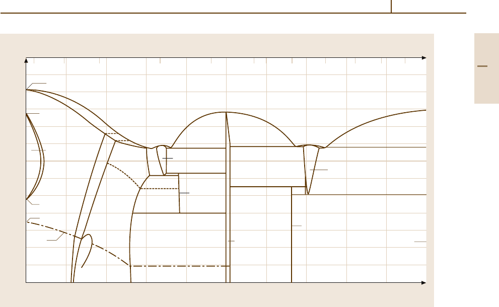
Si.
The phase diagram Fe
−
Si, Fig. 3.1-108, shows
that Si is a strong ferrite former. The main applica-
tion of binary Fe
−
Si alloys is in the form of steels
with ≤ 3.5 wt% Si which have an optimum combina-
tion of high magnetic moment, low magnetostriction,
and low magnetocrystalline anisotropy such that theyare
the ideal material for high induction and low magnetic
power loss applications such as power transformers.
Data are given in Sect. 4.3.2.3.
In Fe
−
C steelmaking, Si is one of the principal de-
oxidizers. It may amount to 0.05–0.3 wt% Si in the steel
depending on the deoxidizing treatment and the amount
of other deoxidants used. At these levels of concentra-
tion Si contributes only moderately to the strength of
ferrite and causes no significant loss of ductility.
Part 3 1.5
Metals 1.5 Iron and Steels 227
2000
1900
1800
1700
1600
1500
1400
1300
1200
1100
1000
1900
800
700
1 5 10 20 30 40 50 60 70 80 90
Fe 10 20 30 40 50 60 70
80
90 Si
T(K)
Si (at. %)
Si (wt %)
Fe–Si
1811 K
1667 K
1185 K
1043 K
1098 K
1238 K
1485 K
1476 K
1333 K
T
C
T
C
Fe
5
Si
3
(Fe
2
Si)
1485 K
1255 K
(FeSi)
70.5
1201 K
(Si)
1480 K
1493 K
1687 K
1683 K
( –Fe)
α
α
1
–FeSi
2
α
( –FeSi
2
)
β
α
2
( –Fe)
γ
Fig. 3.1-108 Fe
−
Si phase diagram [1.82]
3.1.5.2 Carbon and Low-Alloy Steels
The largest group of steels produced both by number
of variants and by volume is that of carbon and low-
alloy steels. It is characterized by the fact that most of
the phase relations and phase transformations may be
referred to the binary Fe
−
C phase diagram or compar-
atively small deviations from it. These steels are treated
extensively in [1.80].
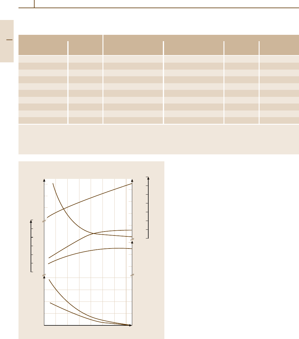
Compositions and Properties of Carbon Steels
According to the effect of carbon concentration on
the phases formed and on their properties, Fig. 3.1-109
shows the variation of the effective average mechanical
properties of as-rolled 25-mm bars of plain carbon steels
as an approximate survey of the typical concentration
dependence.
Carbon steels are defined as containing up to
1 wt% C and a total of 2 wt% alloying elements. Apart
from the deoxidizing alloying elements Mn and Si, two
impurity elements are always present in carbon steels:
phosphorous and sulfur. Phosphorus increases strength
and hardness significantly by solid solution hardening,
but severely decreases ductility and toughness. Only
in exceptional cases may P be added deliberately to
increase machinability and corrosion resistance. Sul-
fur has essentially no effect on the strength properties
since it is practically insoluble in ferrite. However, it
decreases the ductility and fracture toughness. But S is
added deliberately along with an increased Mn content
to promote the formation of MnS. This compound is
formed in small particles which are comparatively soft
and serve as effective chip breakers in free-cutting steel
grades, thus increasing machinability. On the basis of
these effects of the most common alloying and impu-
rity elements, carbon steel compositions are specified
as listed in Table 3.1-41 and free-cutting carbon steel
compositions are specified as listed in Table 3.1-42.
A survey of the alloying elements used and of
the ranges of composition applied in carbon and low-
alloy steels may be gained from the SAE–AISI system
of designations for carbon and alloy steels listed in
Table 3.1-43. Extensive cross references to other stan-
dards may be found in [1.81].
Part 3 1.5
228 Part 3 Classes of Materials
Table 3.1-41 Standard carbon steel compositions applicable to semi-finished products for forging, hot-rolled and cold-finished
bars, wire rods, and seamless tubing [1.80]. Selected grades
Designation Cast or heat chemical ranges and limits
a
(wt%)
UN
SAE-AISI C Mn P
max
S
max
number number
G10050 1005 0.06 max 0.35 max 0.040 0.050
G10100 1010 0.08–0.13 0.30–0.60 0.040 0.050
G10200 1020 0.18–0.23 0.30–0.60 0.040 0.050
G10300 1030 0.28–0.34 0.60–0.90 0.040 0.050
G10400 1040 0.37–0.44 0.60–0.90 0.040 0.050
G10500 1050 0.48–0.55 0.60–0.90 0.040 0.050
G10600 1060 0.55–0.65 0.60–0.90 0.040 0.050
G10700 1070 0.65–0.75 0.60–0.90 0.040 0.050
G10800 1080 0.75–0.88 0.60–0.90 0.040 0.050
G10900 1090 0.85–0.98 0.60–0.90 0.040 0.050
a
When silicon ranges or limits are required for bar and semifinished products, the following ranges are commonly used: 0.10% max;
0.10 to 0.20%; 0.15 to 0.35%; 0.20 to 0.40%; or 0.30 to 0.60%. For rods the following ranges are commonly used: 0.10 max; 0.07–0.15%;
0.10–0.20%; 0.15–0.35%; 0.20–0.40%; and 0.30–0.60%. Steels listed in this table can be produced with additions of leaf or boron.
Leaded steels typically contain 0.15–0.40% Pb and are identified by inserting the letter L in the desingnation (10L45); boron steels can be
expected to contain 0.0005–0.003% B and are identified by inserting the letter B in the desingnation (10B46)
70
60
50
40
30
20
10
0
1200
1000
800
600
400
200
0
340
260
180
100
50
40
30
20
10
0
100
60
20
80
60
40
20
0
0 0.2 0.4 0.6 0.8 1.0 1.2 1.4
Carbon content (%)
Impact
value (J)
Impact
value (ft lbf)
Brinell
hardness (HB)
Tensile
and yield
strength
(ksi)
Tensile
and
yield
strength
(MPa)
Elong-
ation
and re-
duction
of area
(%)
Brinell hardness
Charpy impact
Tensile strength
Yield strength
Reduction of area
Elongation
in 2 in.
Fig. 3.1-109 Variations in average mechanical properties of as-
rolled 25-mm-diam. bars of plain carbon steels as a function of
carbon content [1.80]
Part 3 1.5
Metals 1.5 Iron and Steels 229
Table 3.1-42 Standard free-cutting (re-sulfurized) carbon steel compositions applicable to semi-finished products for forging,
hot-rolled and cold-finished bars, and seamless tubing [1.80]
Designation Cast or heat chemical ranges and limits
a
(wt%)
UN
SAE-AISI C Mn P
max
S
number
number
G11080 1108 0.08–0.13 0.85–0.98 0.040 0.08–0.13
G11100 1110 0.08–0.13 0.30–0.60 0.040 0.08–0.13
G11170 1117 0.14–0.20 1.00–1.30 0.040 0.08–0.13
G11180 1118 0.14–0.20 1.30–1.60 0.040 0.08–0.13
G11370 1137 0.32–0.39 1.35–1.65 0.040 0.08–0.13
G11390 1139 0.35–0.43 1.35–1.65 0.040 0.13–0.20
G11400 1140 0.37–0.44 0.70–1.00 0.040 0.08–0.13
G11410 1141 0.37–0.45 1.35–1.65 0.040 0.08–0.13
G11440 1144 0.40–0.48 1.35–1.65 0.040 0.24–0.33
G11460 1146 0.42–0.49 0.70–1.00 0.040 0.08–0.13
G11510 1151 0.48–0.55 0.70–1.00 0.040 0.08–0.13
a
When lead ranges or limits are required or when silicon or limits are required for bars or semifinished products, the values in Table 5 apply.
For rods, the following ranges and limits for silicon are commonly used: up to SAE 1110 inclusive, 0.10% max; SAE 1117 and over, 0.10%,
0.10–0.20%, or 0.15–0.35%
Table 3.1-43 SAE–AISI system of designations for carbon and low-alloy steels [1.80]
Numerals and digits Type of steel and nominal alloy content (wt%)
Carbon steels
10xx
a
Plain carbon (Mn 100 max)
11xx
Resulfurized
12xx
Resulfurized and rephosphorized
15xx
Plain carbon (max Mn range: 1.00–1.65)
Manganese steels
13xx Mn 1.75
Nickel steels
23xx Ni 3.50
25xx
Ni 5.00
Nickel–chromium steels
31xx Ni 1.25; Cr 0.65 and 0.80
32xx
Ni 1.75; Cr 1.07
33xx
Ni 3.50; Cr 1.50 and 1.57
34xx
Ni 3.00; Cr 0.77
Molybdenum steels
40xx Mo 0.20 and 0.25
44xx
Mo 0.40 and 0.52
Chromium–molybdenum steels
41xx Cr 0.50, 0.80, and 0.95; Mo 0.12, 0.20, 0.25, and 0.30
Nickel–chromium–molybdenum steels
43xx Ni 1.82; Cr 0.50 and 0.80; Mo 0.25
43BVxx
Ni 1.82; Cr 0.50; Mo 0.12 and 0.25; V 0.03 min
47xx
Ni 1.05; Cr 0.45; Mo 0.20 and 0.35
81xx
Ni 0.30; Cr 0.40; Mo 0.12
86xx
Ni 0.55; Cr 0.50; Mo 0.20
Part 3 1.5
230 Part 3 Classes of Materials
Table 3.1-43 SAE–AISI system of designations for carbon and low-alloy steels [1.80] , cont.
Numerals and digits Type of steel and nominal alloy content (wt%)
87xx Ni 0.55; Cr 0.50; Mo 0.25
88xx
Ni 0.55; Cr 0.50; Mo 0.35
93xx
Ni 3.25; Cr 1.20; Mo 0.12
94xx
Ni 0.45; Cr 0.40; Mo 0.12
97xx
Ni 0.55; Cr 0.20; Mo 0.20
98xx
Ni 1.00; Cr 0.80; Mo 0.25
Nickel–molybdenum steels
46xx Ni 0.85 and 1.82; Mo 0.20 and 0.25
48xx
Ni 3.50; Mo 0.25
Chromium steels
50xx Cr 0.27, 0.40, 0.50, and 0.65
51xx
Cr 0.80, 0.87, 0.92, 0.95, 1.00, and 1.05
50xxx
Cr 0.50; C 1.00 min
51xxx
Cr 1.02; C 1.00 min
52xxx
Cr 1.45; C 1.00 min
Chromium–vanadium steels
61xx Cr 0.60, 0.80, and 0.95; V 0.10 and 0.15 min
Tungsten–chromium steels
72xx W1.75; Cr 0.75
Silicon–manganese steels
92xx Si 1.40 and 2.00; Mn 0.65, 0.82, and 0.85; Cr 0 and 0.65
Boron steels
xxBxx B denotes boron steel
Leaded steels
xxLxx L denotes leaded steel
Vanadium steels
xxVxx V denotes vanadium steel
a
The xx in the last two digits of these designations indicates that the carbon content (in hundredths of a weight percent) is to be inserted
Turning to the mechanical properties, it should be
emphasized that the microstructure has a decisive in-
fluence on the properties of all steels. Therefore the
composition and the prior thermal, mechanical, or ther-
momechanical treatments which determine the phase
transformations and ensuing microstructural state of
a steel will always have to be taken into account. Accord-
ingly, tabulated property data will invariably be given
with reference to mechanical and thermal treatments ap-
plied. The terms used and their specific definitions are
outlined in Sect. 3.1.5.1.
In plain carbon steels the C content and mi-
crostructure are determining the mechanical properties.
Manganese is providing moderate solid solution
strengthening and increases the hardenability. The
properties of plain carbon steels are also affected
by the other common residual elements Si, P,
and S. Furthermore, the gasses O, N, and H and
their reaction products may play a role. Their con-
tent depends largely on the melting, deoxidizing
and pouring practice. While Fig. 3.1-109 illustrates
the general effect of C content on the mechanical
properties if the austenite grain size and transfor-
mation microstructure are held essentially constant.
Tables 3.1-44 and 3.1-45 list the mechanical proper-
ties of representative carbon and low alloy steels in
specified states as a function of deformation and heat
treatment.
Part 3 1.5
Metals 1.5 Iron and Steels 231
Table 3.1-44 Mechanical properties of selected carbon and low-alloy steels in the hot-rolled, normalized, and annealed
conditions [1.80]
AISI Treatment Austenitizing Tensile Yield Elongation Reduction Hardness
temperature strength strength in area
No.
a
(
◦
C) (MPa) (MPa) (%) (%) (HB)
1015 As-rolled – 420.6 313.7 39.0 61.0 126
Normalized 925 424.0 324.1 37.0 69.6 121
Annealed 870 386.1 284.4 37.0 69.7 111
1020 As-rolled – 448.2 330.9 36.0 59.0 143
Normalized 870 441.3 346.5 35.8 67.9 131
Annealed 870 394.7 294.8 36.5 66.0 111
1022 As-rolled – 503.3 358.5 35.0 67.0 149
Normalized 925 482.6 358.5 34.0 67.5 143
Annealed 870 429.2 317.2 35.0 63.6 137
1030 As-rolled – 551.6 344.7 32.0 57.0 179
Normalized 925 520.6 344.7 32.0 60.8 149
Annealed 845 463.7 341.3 31.2 57.9 126
1040 As-rolled – 620.5 413.7 25.0 50.0 201
Normalized 900 589.5 374.0 28.0 54.9 170
Annealed 790 518.8 353.4 30.2 57.2 149
1050 As-rolled – 723.9 413.7 20.0 40.0 229
Normalized 900 748.1 427.5 20.0 39.4 217
Annealed 790 636.0 365.4 23.7 39.9 187
1060 As-rolled – 813.6 482.6 17.0 34.0 241
Normalized 900 775.7 420.6 18.0 37.2 229
Annealed 790 625.7 372.3 22.5 38.2 179
1080 As-rolled – 965.3 586.1 12.0 17.0 293
Normalized 900 1010.1 524.0 11.0 20.6 293
Annealed 790 615.4 375.8 24.7 45.0 174
1095 As-rolled – 965.3 572.3 9.0 18.0 293
Normalized 900 1013.5 499.9 9.5 13.5 293
Annealed 790 656.7 379.2 13.0 20.6 192
1117 As-rolled – 486.8 305.4 33.0 63.0 143
Normalized 900 467.1 303.4 33.5 63.8 137
Annealed 855 429.5 279.2 32.8 58.0 121
1118 As-rolled – 521.2 316.5 32.0 70.0 149
Normalized 925 477.8 319.2 33.5 65.9 143
Annealed 790 450.2 284.8 34.5 66.8 131
1137 As-rolled – 627.4 379.2 28.0 61.0 192
Normalized 900 668.8 396.4 22.5 48.5 197
Annealed 790 584.7 344.7 26.8 53.9 174
1141 As-rolled – 675.7 358.5 22.0 38.0 192
Normalized 900 706.7 405.4 22.7 55.5 201
Annealed 815 598.5 353.0 25.5 49.3 163
1144 As-rolled – 703.3 420.6 21.0 41.0 212
Normalized 900 667.4 399.9 21.0 40.4 197
Annealed 790 584.7 346.8 24.8 41.3 167
1340 Normalized 870 836.3 558.5 22.0 62.9 248
Annealed 800 703.3 436.4 25.5 57.3 207
3140 Normalized 870 891.5 599.8 19.7 57.3 262
Annealed 815 689.5 422.6 24.5 50.8 197
Part 3 1.5