Marjoribanks R. Geological Methods in Mineral Exploration and Mining
Подождите немного. Документ загружается.

2.2 Mapping Using Reflectance Imagery as a Map Base 35
C 347
C 295
C 343
C 345
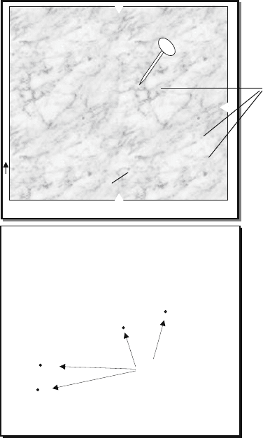
Pin holes
(size exaggerated)
BACK OF PHOTO
CLONCURRY AREA
Run 17
148
—
Pin holes are
labelled on the bac
k
of the photo to
correspond to field
notebook entry
and/or to a sample
number
Positions located o
n
photograph where
an observation has
been made or a
sample taken
There may not be
enough room to
clearly label all
these points on the
face of the
photograph
Prick a hole
through the photo
using a thin, sharp
pin
×
×
×
×
Fig. 2.8 Using a sharp pin to transfer location points from the face to the back of a photograph.
Annotating points on the back of the photo leaves the face side clear for geological interpreta-
tion.
negligible) should be used. Enlarged photos cannot be easily viewed stereoscopi-
cally so a standard-scale stereo pair should be kept handy to aid in field positioning
and interpretation.
The enlarged photo will usually be too big to be handled in the field and may
have to be cut into smaller pieces. Such cut-down images have to be treated with
great care because mapping needs to be carried right to their edges. This is because
there is no overlap with adjacent images and no protective border around each cut-
down photograph. The same problem arises when working in the field with large
satellite images. To overcome this problem the following procedure is recommended
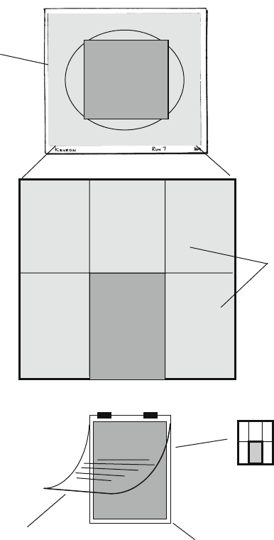
(Fig. 2.9):
• Cut the images into as large portions as can be conveniently handled in the field.
For most geologists this is probably about 60 × 40 cm.
36 2 Geological Mapping in Exploration
Only enlarge
central 60%
of image
where
distortion is
least
Enlargement
may be too
large for easy
handling in
the field.
It should be
cut into
smaller pieces
to fit field
mapping
board
Each photo
portion should be
mounted on to
thin card allowing
a protective
overlap along
each edge
Identify position of each
photo portion by symbol or
letter on back
Attach clear overlay to one edge
using masking tape. Record
observation on to overlay.
Thin card backing glued on.
(use spray on glue and dry
between weighted boards to
prevent buckling)
Cut into
manageable
field sheets
using scalpel
and straight
edge
STANDARD AIR
PHOTOGRAPH
ENLARGED AI
R
PHOTO
B2
1:20000
A1 B1
C1
A2 B2 C2
1: 2000
Photo portion
Fig. 2.9 Preparing an air photo enlargement for geological mapping
• Glue each photo portion to a backing of thin card using a spray adhesive.
The backing should be slightly larger than the image to protect its edges from
becoming dog-eared.
• Clearly label each photo portion on the back with a code so that adjacent photo
portions can be quickly identified. A matrix system using letters for columns and
numbers for rows works well. The back of each photo portion should also be

2.2 Mapping Using Reflectance Imagery as a Map Base 37
marked with the scale, north arrow, original run and print number and any other
relevant details about the project.
• Attach drafting film overlays to the photos in the manner described for preparing
standard size prints.
• Make a field mapping clip-board out of a piece of hardboard and several spring
clips.
• The board should be a few millimetres wider all round than the photos. When not
in use, a second board of the same size can be used as a protective cover for the
prints.
2.2.8 Data Transfer to Base Map
With air photographs, because of the scale distortion, geological boundaries plot-
ted on an overlay do not represent an accurate map projection. Although the errors
on any one photograph are not be great, if interpretations from adjacent photos are
combined to make a larger map, the resulting errors can be cumulative and even-
tually may cause a gross distortion of true geological relationships. Ideally, the
interpretation of each photo can be transferred on to an orthophoto
19
by match-
ing features. Orthophotos are, however, not always available and are expensive to
produce. Geological interpretation can also be plotted on to a photo-mosaic, but
such mosaics also contain localized scale distortions and discontinuities. The easi-
est way therefore is to transfer the interpreted data from each photo overlay on to a
scale-correct map base.
The ideal topographic base map for plotting photo geology should have the
following features:
• The same scale as the photographs (a print can be photo enlarged or reduced if
necessary);
• Sufficient topographic/cultural features (rivers, tracks, fence lines, buildings, etc.)
to enable the photos to be exactly located;
• No unnecessary detail which would tend to obscure the geological information
to be plotted on it;
• Availability on transparent drafting film.
Maps with these features can often be bought directly from government mapping
agencies and are known as a line base. In most developed countries topographic
19
An orthophoto is a distortion-free photographic image produced from standard air photos by
computer scanning. Once in digital format the image is corrected for radial distortion and a Digital
Elevation Model (DEM) is used to correct for altitude differences across the scene. The process is
known as ortho rectification. An orthophoto map is an orthophoto to which metric grid coordinates
and (sometimes) annotated line work identifying topographic/cultural features has been added – a
process called georeferencing. For more on orthorectification and georeferencing see Chap. 10.
38 2 Geological Mapping in Exploration
map data are also available in digital form. It is possible to buy these data on disc
or on-line and to edit the base map required using a CAD (computer aided drafting
software) system. A print-out of a line base can then be made at an appropriate scale
on film or paper.
The procedures recommended for transferring geology from an air photo overlay
to the line base are as follows:
• Check with the base map to see which features on the map can also be seen on the
photograph. Ideal features are points such as fence corners, bends in roads, bends
in rivers or river junctions, wind-pumps, buildings, etc. Trace the more important
of these features on to the photo overlay. It is particularly important to pick up
features near the edges of the photo where a match will need to be made with
data on the adjacent photo; this is also the area where scale distortion is greatest.
Fewer control points need to be identified in the photo centre. It is a good idea
to use colour to distinguish this topographic/cultural detail on the overlay from
lines and symbols showing the interpreted geology.
• Place the photo overlay below the base map and position its centre point by
matching the selected features common to map and photograph. Mark the photo
centre onto the base map. Maps showing plotted photo centres can often be
bought from the same agency that sells the photographs, but such maps are
designed as a guide for purchasing only and are not very accurate. Plot your
own centres.
• Trace the geological interpretation on to the base map starting from the centre of
the overlay. As the tracing moves out from the centre, move the overlay so as to
maintain a match between overlay and line base, using the reference topographic
features adjacent to the geology being traced.
There is an element of necessary fudging in this technique to achieve smooth
geological boundaries. Special care has to be taken in the overlap areas between
photographs. Limited scale and angular distortions will inevitably creep in, but if
the above procedure is followed these errors will be small, localized, non cumulative
and will not affect essential geological relationships.
2.3 Mapping with a Plane Table
This section describes how to make a geological map using a simple plane table. A
plane table is a small horizontally-mounted mapping board used in the field so that
the bearings to features of interest can be directly plotted onto a paper sheet pinned
to the board.
Before the mapmaking process begins, the geologist must study the area and
determine what features are to be recorded.
The plane table is a small board, generally about 50–60 cm square, mounted
horizontally on a tripod and locked to face in any chosen direction. Plane tables
2.3 Mapping with a Plane Table 39
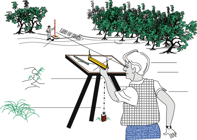
OUTCROP
PEEPSIGHT
ALIDADE
TRAVERSE
BOARD
Fig. 2.10 Detailed geological outcrop mapping using a plane table. In this example, a simple
home-made peep-sight alidade is being used
(sometimes called “traverse boards”) are made especially for this job, but one can
readily be made to fit on to the tripod support of a theodolite (Fig. 2.10).
The essential beginning for any survey is establishing two points in the survey
area at a known distance apart and within easy sighting distance of each other (say
up to 200 m). These positions will be referred to as the first and second survey
points; once established using a surveyor’s tape or chain, they are marked on the
ground with a peg or flagging tape, or both.
The plane table is mounted in a horizontal position directly above the first survey
point and oriented with a compass so that one edge faces north. It is then locked
in that position. A sheet of paper is fixed on to the table and a mark is made at
some suitable place on the paper to indicate the position of the table. A sighting
instrument called an alidade is then laid on the map with one edge on the marked
set-up point. In the illustration of Fig. 2.10, a simple home-made alidade, called a
peepsight alidade, is being used.
The alidade is rotated around the marked point so as to sight on to the second
survey point. A pencil line is then drawn along the edge of the alidade, marking
the bearing to the second point. Because the distance between the two points is
known, the position of the second point can now be plotted on the map according to
a suitable scale.
Now the lines marking the bearings to any other points of interest within the view
of the observer can be marked on to the map in the same way, radiating out from the
40 2 Geological Mapping in Exploration
1
2
50 meters
1
2
50 meters
Ground feature A
A
Plane table map
Plane table map
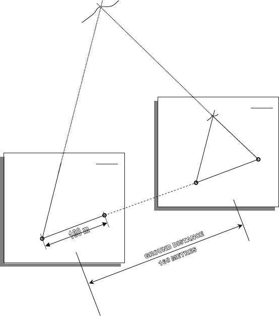
Fig. 2.11 Positioning a point by triangulation during plane table mapping. Points 1 and 2 are at a
known distance apart – in this case 160 m. By positioning the plane table over each point in turn,
and taking bearings on the feature A, its map position can be established
first set-up point (Fig. 2.11). It is not necessary to measure any of these bearings with
a compass. The features on which sightings are made can be geological, topographic
or cultural features, or arbitrary survey points. The best technique is to sight on to a
survey pole that is moved from point to point by an assistant on the instructions of
the mapper – portable 2-way radios will help with this process. The assistant then
identifies and labels each survey point (using a marker such as a peg or flagging
tape). The identification of the bearing is also recorded on to the map.
When the bearings of as many features as required have been recorded in this way
as a series of lines on the map, the plane table is then moved to a position above the
second starting point. The table is then rotated around its vertical axis so that the line
marking the bearing between the two starting points is back-sighted on start point
one; the table is then locked in this position. Now a second set of bearing lines,
radiating out from the second start position, are taken to all the features that were
2.4 Mapping on a Pegged Grid 41
identified. Where the two bearing lines on any one feature cross, that point is exactly
positioned on the map – this process is known as triangulation. Any difference in
relative levels between the surveyed points does not affect the accuracy of the map
projection. Once a network of survey points have been established in this way, the
survey can be infinitely extended in any direction by selecting any two of these
points as the base line for new triangulations.
Plotting geological observations on to the survey base depends on using the
exactly positioned survey points for control. In most cases these points will have
been chosen on geological features and will have been put in closely where the
geology is complex. With a large network of suitably positioned survey points, it is
a relatively easy task to sketch in geological boundaries between the known points.
In a plane table survey, it is necessary to know in advance what geological features
are to be recorded and to select the survey points accordingly. Another technique
is for the geologist to walk the outcrop with survey marker in hand, calling out
(or using a radio transceiver) to the assistant to take the appropriate bearings and
record geological data that is dictated. The technique or mix of techniques that are
chosen will depend on the geologist, the assistance available, and the nature of the
surveying/geological problem.
In heavily vegetated or hilly country, survey points can only be established where
sighting lines are possible. Detail between the networks of triangulated points will
have to be subsequently mapped in by means of a tape and compass survey.
For prospect mapping, the simple set-up described above is probably all that
the geologist will need, especially as more complex survey instruments may not be
available. However, more sophisticated alidades can simplify the mapping process.
By sighting through the ocular of a telescopic alidade, more accurate bearings over
much greater distances can be made. If the assistant carries a graduated survey staff,
the interval between two sighting hairs (called stadia hairs) superimposed on the
telescopic image of the staff, provide a direct measure of the distance to the staff.
The position of the point can then be directly plotted on the map without the need
for triangulation. This surveying process is called tacheometry. The inclination of
the telescope, recorded on a built-in scale, gives the vertical angle to the plotted
point, and can be used to make a contour map of the area of the survey. Modern
electronic distance-measuring survey instruments, employing reflected infra-red or
laser beams, can also be used for plane table map-making.
2.4 Mapping on a Pegged Grid
2.4.1 Requirements of the Grid
A pegged grid consists of a regular array of pegs or stakes placed in the ground at
accurately surveyed positions and used to provide quickly accessible survey control
points to locate all subsequent exploration stages. The following points should be
borne in mind:

42 2 Geological Mapping in Exploration
• Ideally, for detailed geological mapping purposes, at least one grid peg should be
visible from any point within the area to be mapped. Such grids may therefore
need to be closer spaced than a grid designed solely for collection of geochemical
or geophysical data. This aspect should be considered at the planning stage of the
programme. In relatively open country, a grid spacing of 80 × 40 m is ideal.
• The orientation of grid lines should be at a high angle to the dominant strike of
the rocks, to the extent that the strike is known.
• As a general rule, grids used for mineral exploration do not have to be estab-
lished with extreme accuracy – placing pegs to within a meter or so of their
correct position is acceptable. All types of data collected on the grid – geology,
geochemistry, geophysics, drill hole data – will still correlate. If it ever becomes
important, the position of any feature can be subsequently established to whatever
level of accuracy is desired.
• To prevent small surveying errors from accumulating into very large errors, the
grid should be established by first surveying a base line at right angles to the
proposed grid lines. Points on the base line should be surveyed in as precisely as
possible using a theodolite and chain. The theodolite is then used to accurately
establish the right angle bearing of the first few pegs on each cross line of the
grid.
20
From this point, the remainder of the grid pegs can be rapidly placed by
using a tape for distance and simply back-sighting to maintain a straight pegged
line. Where dense vegetation or rugged topography prevents back-sighting, short
cross lines can be pegged using a compass and tape. For grid lines over about
1 km long, tape and compass surveying can cause unacceptable cumulative errors,
and positioning with a theodolite is recommended.
• In hilly country, the establishment of an accurate grid requires the use of slope
corrections. The slope angle between the two grid positions is measured with a
clinometer. To obtain the slope distance which corresponds to a given horizon-
tal grid distance, divide the required grid distance by the cosine of the slope
angle. This calculation can easily be done with a pocket calculator but since
the grid spacings are fixed, a sufficiently accurate slope distance for any given
slope angle can quickly be read off from a table of pre-calculated values such as
Table 2.2.
• If a detailed contour map is not otherwise available, the slope angle between pegs
should be recorded and used to compile a contour map of the area. Contours are
essential in hilly country to understand the outcrop patterns of rock units on the
map, particularly in regions of shallow dipping beds.
• Grid peg spacing in distances that are multiples of 20 m should be considered,
as this allows for more even subdivisions than the more traditional multiples of
50 m.
20
Establishing a cross line at right angles to a base line can also be done using an optical square –
a hand-held sighting instrument which enables two pegs to be placed so as to form a right angle
with the observer.

2.4 Mapping on a Pegged Grid 43
Table 2.2 Table for converting slope distance into horizontal distance
Horizontal distance (m)
Slope
angles
(degrees) 5 10 20 25 40 50 60 75 80 100
Slope distance (m)
5 5.0 10.0 20.1 25.1 40.2 50.2 60.2 75.3 80.3 100.4
10 5.1 10.1 20.3 25.4 40.6 50.8 60.9 76.1 81.2 101.5
15 5.2 10.3 20.7 25.9 41.4 51.8 62.1 77.6 82.8 103.5
20 5.4 10.6 21.3 26.6 42.5 53.2 63.8 79.8 85.1 106.4
25 5.5 11.0 22.1 27.6 44.1 55.2 66.2 82.8 88.3 110.4
30 5.8 11.5 23.1 28.9 46.2 57.7 69.3 86.6 92.4 115.4
35 6.1 12.2 24.4 30.5 48.8 61.0 73.3 91.6 97.7 122.1
40 6.5 13.0 26.1 32.6 52.2 65.3 78.3 97.9 104.4 130.5
45 7.1 14.1 28.3 35.4 56.6 70.7 84.9 106.1 113.1 141.4
50 7.8 15.5 31.1 38.9 62.2 77.8 93.3 116.6 124.4 155.5
55 8.7 17.4 34.8 43.5 69.7 87.1 104.5 130.7 139.4 174.2
60 10.0 20.0 40.0 50.0 80.0 100.0 120.0 150.0 160.0 200.0
• The origin of the grid should lie well beyond the area of interest so that all grid
coordinates in the area are positive whole numbers. Conventionally, the origin is
placed to the southwest of the area so that all coordinates can be expressed as
distances north (northing) or east (easting) of the grid origin.
• If possible, choose the origin of the grid so that easting and northing coordinates
through the prospects of principal interest have dissimilar numbers. This will help
to reduce potential future errors.
• Where a grid oriented N–S and E–W is required, consider using national metric
grid coordinates (i.e. UTM, see Sect. 10.5). The advantage of this is that pub-
lished map-based data sets can be easily tied to the local grid observations. Using
national metric coordinates requires that at least one point on the ground grid is
accurately positioned by survey into the national grid. Only the last four digits of
the regional grid need be shown on the grid pegs.
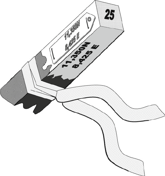
• Clearly and permanently label grid pegs as shown in Fig. 2.12. Wooden pegs are
usually cheapest and are ultimately biodegradable. For a more permanent sur-
vey consider using galvanized steel markers (fence droppers make good survey
pegs). Steel pegs are essential in areas where bush fires and/or termite activity is
common and the grid is required to last for more than one season.
2.4.2 Making the Map
Mapping is carried out on to field sheets that are generally graph paper of A3
or A4 size. The thin, shiny-surface papers of most commercially available pads
of graph paper make poor field mapping sheets. If possible, use a heavyweight,
44 2 Geological Mapping in Exploration
Aluminium tag stapled on
Ground placement
sequence number
Bright coloured plastic
flagging tape
Coordinates in black
marker pen on white paint
background
Coordinates impressed on
to aluminium tag
Fig. 2.12 Recommended labelling system for grid pegs. These are short wood or steel stakes
hammered into the ground at regular surveyed intervals to provide ongoing survey control for all
exploration stages from geological mapping to drilling
matt-surface paper with a 1 cm ruled grid (you may have to get these specially
printed). Waterproof sheets of A4 graph paper are available if mapping has to be
carried out in wet conditions.
The positions of the grid pegs are marked on to the map sheets according to the
scale chosen before field work commences. Field map sheets are valuable docu-
ments and, along with any field notebooks, should be carefully labelled and filed at
the end of the work. Usually the area to be mapped is larger than can be covered by
one field sheet. In setting up the field sheets, allow for an overlap between adjacent
sheets and clearly label each sheet so that adjacent sheets can be quickly located.
As a surveying aid, at an early stage in the mapping process, it is of great value
to create an extra network of location lines on the map sheet by surveying on to the
map any topographic or cultural features of the area such as ridge lines, streams,
tracks, fence lines, etc. that may be present. In the example shown (Fig. 2.13),
the survey control provided by a 100 × 50 m pegged grid was supplemented by
first surveying the stream, track, fence line, costeans and drill holes on to the map