Marjoribanks R. Geological Methods in Mineral Exploration and Mining
Подождите немного. Документ загружается.


2.1 General Considerations 15
by non-professionals and the map can be compiled and plotted by computer accord-
ing to pre-set formulae. A geological map, on the other hand, is not contoured point
data but an analog presentation of ideas; ideas backed up by detailed, careful obser-
vation and rational theory but, nevertheless, ideas. To be a successful geological
map-maker, it is necessary to keep this concept firmly in mind, and throw out any
idea of the geological map-maker as an objective collector of “ground truth”
3
data.
After all, one geologist’s “ground truth” may be another geologist’s irrelevant noise.
2.1.3 Intelligent Mapping
Producing a geological map is a process of problem solving. One of the best ways
to approach problem solving is known as the system of multiple working hypothe-
ses.
4
In practice this means that the geologist does not start the field work with a
completely blank mind, but armed with ideas about the geology which has to be
mapped. These ideas are developed from looking at published maps, from inter-
preting air photos, satellite images or aeromagnetic data or even by following an
intuitive hunch. From these ideas or hypotheses, predictions are made: areas are
then selected and observations are made which will most effectively test these
predictions. Sometimes this will involve walking selected traverses across strike,
sometimes following a marker horizon or contact, sometimes a more irregular search
pattern. The mapping sequence depends on the postulated geology: strong linear
strike continuity usually indicates that across-strike traversing is the best approach;
complex folding or faulting is best resolved by following marker horizons, and
so on. In any case, the early working hypotheses will certainly contain several
alternative scenarios and may not be precisely formulated; to check them out a
very wide range of field observations will have to be made and a mix of differ-
ent search patterns may need to be followed. The geologist at this stage must be
open to all possible ideas, hypotheses and observations. If the observations do not
fit the hypotheses, then new hypotheses must be constructed or old ones modified to
accommodate the observations. These new hypotheses are then tested in their turn,
and so the process is repeated.
With each step in the process the predictions become more precise and the search
pattern more focused on to the key areas of interest. These are the usually areas
where significant boundary conditions can be defined in the outcrop. Most of the
time of the intelligent mapper is thus spent in the areas of “fertile” outcrop where
there is most to be learned, and less time is spent in those areas where the rocks are
uniform – in the latter areas a lower density of observation will serve (Fig. 2.1).
3
“Truth” and “fact” are slippery concepts that are often employed to claim authority and stifle
debate. They are best not used in scientific contexts.
4
The concept of multiple working hypotheses, now widely acknowledged as a basic part of the
scientific method, was first enunciated by geologist Thomas Chrowder Chamberlin (1897).
16 2 Geological Mapping in Exploration
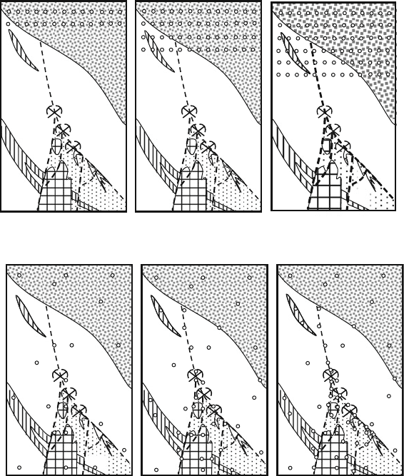
Style 1: The systematic data collector (the mindless slogger)
Style 2: The ideas-driven intelligent mapper
Day one: 20 data points Day three: 60 data points
Day one: key outcrops
Regional overview
Preliminary interpretation
Day two: 40 key outcrops
Focus on contacts and
major structure
Day three: 60 key outcrops
Job Complete!
Day two: 40 data points
Fig. 2.1 Comparison of geological mapping styles. In the first case, the “systematic data collec-
tor”, driven by a pre-determined inflexible strategy rather than ideas, regularly traverses the ground.
The task will eventually be completed, but this is not the most efficient procedure. The intelligent
mapper on the other hand continuously assesses the significance of each outcrop against evolving
ideas about geology, and then determines strategy in the search for the next significant outcrop.
The job is completed more quickly, and better too
Many small structural features can be observed in individual outcrop or hand
specimens that allow predictions to be made about large structures occurring at the
scale of a map. Most useful of such observations are the predictable geometrical
relationships that occur between bedding, cleavages, lineations and folds, as well as
movement indicators that can be used to deduce the sense of movement on brittle
faults and ductile shear zones. Where such structures as these occur, they are a boon

2.1 General Considerations 17
to the field mapper, and he should learn to recognize and make use of them. A
detailed description of these structures is beyond the scope of this book but they
are treated in many standard geology texts. Some useful references will be found in
Appendix F.
Another aspect of rocks is the way the features and relationships seen in hand
specimen or outcrop often exactly mirror features occurring at map scale. This has
been informally called “Pumpelly’s Rule” after Raphael Pumpelly, the nineteenth
century USGS geologist who first described it.
5
Once again the intelligent mapper
will be on the look out for such potential relationships in outcrop as a means of
developing ideas as to the map scale geological patterns.
With geochemistry having a major role in most modern exploration programmes,
the geological map will usually play a large part in the planning and understanding
the results of surface geochemical sampling programmes. In order to fulfil this role,
exploration geological mapping in most cases will need to carefully show the dis-
tribution of superficial and weathered rock units (the regolith), as well as bedrock
features.
Observations are thus not made randomly, nor are they collected on a regular grid
or according to a fixed search pattern; rather they are selected to most effectively
prove
6
or disprove the current ideas. Geological mapping is a scientific process
and when carried out properly corresponds to the classic scientific method: theoriz-
ing, making predictions from the theories, and designing experiments (planning the
required field observations) to test the predictions.
7
An aspect of this technique is that thinking and theorizing are constantly being
done while field work proceeds. In other words, data collection is not a separate and
earlier phase from data interpretation; these two aspects are inextricably linked and
must proceed together. Above all, observation and interpretation should never come
to be regarded as “field work” and “office work”.
8
5
Today we recognize that geological processes are essentially chaotic (i.e. non-linear). Such
systems typically exhibit what is called “scale-invariance”, meaning there is a repetition of char-
acteristic patterns at different scales – the example often quoted being the comparison in shape
between a rock pool and the coastline of which it is an element. Pumpelly’s Rule is an early
recognition of this type of relationship (see Pumpelly et al., 1894).
6
Actually, as pointed out by the philosopher of science Karl Popper (1934), an experiment either
falsifies a hypothesis or expands the range of conditions under which it can be said to hold good:
it can never prove it.
7
All theories in science, and that includes ideas on geology, must be formulated in such a way that
they are capable of being falsified. For example, for field mapping purposes it is not very useful
to postulate that “these outcrops constitute a metamorphic core complex” because there is unlikely
to be a simple observation which can falsify that statement. Rather postulate “this outcrop is felsic
gneiss, that outcrop is sandstone, this contact is a mylonite” – if these turn out to be false then the
hypothesis may need revision.
8
In our society from the earliest training we are unfortunately conditioned to think indoors, and to
enjoy less cerebral pursuits outdoors. It is a syndrome that the field geologist must learn to break.
18 2 Geological Mapping in Exploration
2.1.4 Choosing the Best Technique
The mapping technique used depends upon the availability of suitable map bases
on which to record the field observations. A summary of the different techniques is
given in Table 2.1.
The ideal base is an air photograph or high resolution satellite image, as these
offer the advantages of precise positioning on landscape/cultural/vegetation features
combined with an aerial view of large geological structures that cannot be seen from
the ground. For small-scale maps (say 1:5,000–1:100,000) remote sensed images
are virtually the only really suitable mapping base, although if good topographic
maps are available at these scales they can be used as a second-choice substitute. In
Third World countries, where there is often no aerial photography available at any
suitable scale, satellite imagery can provide a suitable base for regional geological
mapping. Radar imagery, whether derived from satellite systems or special aircraft
surveys, can also be used as a geological mapping base in much the same way as
aerial photography.
In the special case of mine mapping, the mapping base is usually a survey plan
of the mine opening prepared by the mine surveyor and supplemented by accu-
rately established survey points from which distances can be taped. In open-cut
mines, most available rock surfaces are vertical or near-vertical; observations are
thus best recorded onto sections and afterwards transferred to the standard level
plans, a composite open-cut plan or mine sections. In underground mines, obser-
vations can be made on the walls, roofs and advancing faces of openings, and are
then recorded and compiled onto a section or plan. These mapping techniques are
detailed in subsequent sections.
For surface mapping, suitable photography is often not available or is only avail-
able at too small a scale to permit photo enlargement for detailed mapping purposes.
In many cases also, air photographs are difficult to use for precise field location
because of vegetation cover or simply because of a lack of recognizable surface
features. In areas of very high relief, photos can also be difficult to use because
of extreme scale distortions. In these cases, alternative techniques are available
to provide the control for detailed mapping. In order of decreasing accuracy (and
increasing speed of execution) these mapping techniques are: plane table mapping,
mapping on a pegged grid, tape and compass mapping, and pace and compass
mapping.
Plane table mapping is seldom done nowadays because it is slow and the alter-
native use of pegged grid control can provide all the surveying accuracy that is
normally required for a geological map. Further disadvantages of the plane table
technique are the requirement for an assistant and the fact that geological obser-
vation and map-making usually have to be carried out as two separate processes.
However, plane tabling provides great survey accuracy and is an invaluable tech-
nique where precision is needed in mapping small areas of complex geology. Such
situations often arise in detailed prospect mapping or in open-cut mine mapping.
The plane table technique is also indicated where a pegged grid cannot readily be

2.1 General Considerations 19
Table 2.1 Comparison of mapping techniques
Mapping
technique Ideal scales Indications Advantages Disadvantages
Pace and compass 1:100–1:1,000 Rough prospect
map. Infill
between survey
points
Quick. No
assistance and
minimal
equipment
needed
Poor survey accuracy,
especially on
uneven ground
Tape and compass 1:100–1:1,000 Detailed prospect
maps. Linear
traverse maps.
Mine mapping
Quick. Good
accuracy. No
preparation
needed
May need assistance.
Slow for large
equidimentional
areas
Pegged grid 1:500–1:2,500 Detailed maps of
established
prospects
Fair survey
accuracy.
Relatively
quick. Same
grid controls/
correlates all
exploration
stages
Expensive. Requires
advance
preparation. Poor
survey control in
dense scrub or hilly
terrain
Plane table 1:50–1:1,000 Detailed prospect
mapping in areas
of complex
geology. Open
cuts
High survey
accuracy. No
ground
preparation
required
Slow. Requires
assistance.
Geological
mapping and
surveying are
separate steps
GPS and DGPS 1:5,000–1:25,000 Regional and
semi-regional
mapping. First
pass prospect
mapping
Quick, easy
downloadable
digital survey
data. Good
backup for
other
techniques at
similar scales
Encourages
geological mapping
as collection of
point data
Topographic map
sheet
1:2,500–1:100,000 Regional mapping
and
reconnaissance.
Areas of steep
topography. Mine
mapping. Base
for plotting GPS
observations
Accurate
georeferenced
map base.
Height contours
Difficulty in exact
location. Irrelevant
map detail obscures
geology. Not
generally available
in large scales
Remote sensed
reflectance
imagery
1:500–1:100,000 Preferred choice.
Ideal geological
mapping base at
all scales
Geological
Interpretation
directly from
image. Stereo
viewing. Easy
feature location
Scale distortion (air
photos). Expensive
if new survey needs
to be acquired

20 2 Geological Mapping in Exploration
used, for example, mapping a disused quarry or open cut. Plane table mapping is
therefore a useful skill for a field geologist to acquire.
Pegged grids are used for outcrop mapping at scales of 1:500–1:2,500 and are
a commonly used survey control for making detailed maps. The technique relies
on placing a close network of survey pegs into the ground at regular stations on a
Cartesian coordinate system (see Sect. 10.5.2). The coordinates are marked onto the
pegs that are then placed in the ground to provide control for all stages of exploration
over the area. The disadvantages of using a pegged grid lies in its expense, and the
danger that geologists often come to regard the grid as a series of predetermined
geological traverse lines, rather than a pre-positioned network of points for survey
control.
A measuring tape and compass or Hip-Chain
TM
and compass survey allows for
quick production of detailed prospect maps, or maps to provide a base for location
of sample points in areas where the geologist cannot spend long on site. With this
technique it is possible to produce a high-quality, detailed geological map without
needing any advance preparation (provided there is a tape or hip-chain available
9
).
If there is no measuring tape available then pacing distances can still allow a
rough map to be constructed. Pacing is better than estimation and has the advantage
of being quick. Pacing can even be reasonably accurate for short distances over open
flat ground. Explorationists should be aware of their normal pace length by laying
out a 100 m tape along flat even ground and checking pace length by walking back
and forward many times (using a normal, easy stride) and taking an average. Every
time a pegged grid line is walked, the pace length over different types of terrain
should be checked.
2.1.5 Choosing the Best Scale
The scale chosen for mapping controls the type of data which can be recorded and
hence the type of observations which are made in the field (see Fig. 2.2). The choice
of appropriate scale depends on the purpose in making the map.
A small-scale map – say at 1:25,000 or smaller – shows broad regional patterns
of rock distribution and major structures. From an exploration point of view this is
the scale at which the prospectivity of a basin, fold belt, tectonic unit or other large
geological subdivision might be determined. It is a scale appropriate for develop-
ing ideas for new project generation. Explorationists do not often make maps at
these small scales. There are two reasons for this: firstly, this is the type of mapping
undertaken by Geological Surveys and can often be bought off the shelf; secondly,
9
Hip-Chain
TM
is a reel of disposable, biodegradable cotton thread. As it reels from its spool, a
meter records the length wound off, and hence the distance travelled. The thread is then sim-
ply broken and left on the ground. Other brand names for similar measuring instruments are
Fieldranger
TM
, Chainman
TM
and Topofil
TM
.
2.1 General Considerations 21
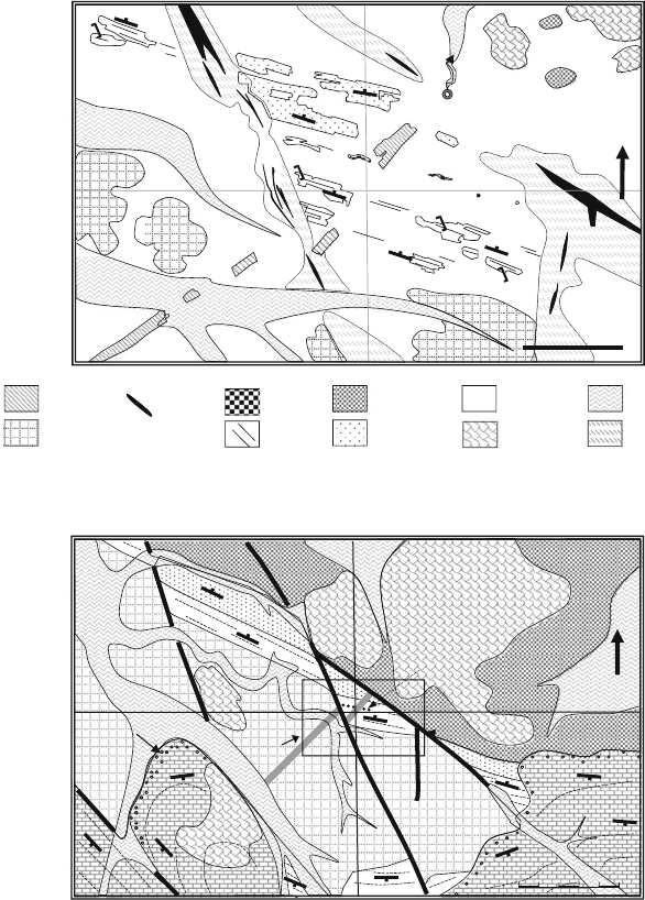
GRANITE
SHALE
GOSSAN
SANDSTONE
BASALT
LATERITE
DOLERITE
COLLUVIUM ALLUVIUM
QUARTZ
QUARTZ FLOAT
WOLLOMAI PROSPECT 1:1000 SCALE - OUTCROP MAPPING
WOLLOMAI PROSPECT 1: 5000 SCALE - DETAILED REGIONAL MAPPING
100 M
Red-brown soils
Red-brown
soils
Red-brown soils
sandy soil
sandy soil
sandy soil
sandy soil
sandy soil
sandy soil
spring
60
48
60
55
58
56
85
80
83
80
sandy
soil
Red-brown
soils
1:1000
map
area
Gossan
65
60
48
52
8
5
8
40
5
10
50
10
48
500 0
meters
N
Conglomerate
N
Fig. 2.2 How the scale chosen affects the style and content of geological maps of the same area.
Generalisation is required at all scales. There is no such thing as a “fact” map. However, the
component of field observation is greatest in large-scale maps
explorationists in most cases cannot obtain a sufficiently large tenement holding to
make this kind of mapping worth while.
Maps with intermediate-range scales between 1:25,000 and 1:5,000 can be
described as detailed regional maps. These are appropriate scales for the first-
pass mapping of large tenement holdings. They are also ideal scales to use when
22 2 Geological Mapping in Exploration
combining geological mapping with regional prospecting or regional geochemistry
(such as stream sediment sampling). At scales in this range, some of the larger
features which might have had an effect on the localization of ore are capable of
being shown, although the outline of an ore deposit itself could not generally be
shown. The intermediate range of map scales is therefore suitable for the control
and development of new prospect generation.
On maps at scales more detailed than 1:5,000, individual outcrops or outcrop
areas and the surface expression of significant areas of mineralization can be shown.
These scales are appropriate for showing the features that directly control and local-
ize ore. Maps at these scales are often called outcrop maps and the need to make
them generally arises after a prospect has been defined. The purpose of such maps
is to identify the size, shape and other characteristics of the potential ore body. The
map is then used to help specify, control and evaluate all subsequent programmes of
detailed prospect exploration including geophysics, geochemistry and drilling.
2.1.6 Measuring and Recording Structures
To fully define and understand the attitude of a planar surface such as a bedding
plane, cleavage, joint, vein etc., a geologist needs to know its strike, its dip and
the direction of the dip towards one of the principal compass quadrants. Of these
measurements, the strike is usually the most important, because it is that which
defines the potential continuity of the surface in the horizontal plane of a geological
map, or between the adjacent sections of a drilling program. When measurements
are recorded digitally (as opposed to analog recording as a strike and dip symbol on
a map) the most common traditional way has been in the form of xxx/yy/A, where
xxx (the strike) is a 3-digit compass bearing (000–360
◦
), yy (the dip) a two digit
number representing the angle from the horizontal (00–90
◦
) and A is the direction
of dip towards a principal compass direction or quadrant (i.e. N, NE, E, SE, S, SW,
W or NW). As an example: 042/23 NW is a surface with strike of 42
◦
that dips
at 23
◦
to the northwest. Because this method requires three data fields (strike, dip
and dip direction) the advent of computer-based databases has lead to a variety of
other ways, utilising only two data fields, being employed for digital recording of
the measured attitude of planes. These involve recording attitude as dip and dip
direction, or as a simple strike and dip with the dip direction qualifier recorded by
means of a convention in the way the strike number is expressed. The most common
of these conventions is the so-called “right-hand rule”. This rule can be explained
thus: imagine grasping a strike/dip map symbol with the right hand, palm down and
fingers pointing in the direction of dip. The thumb then indicates the strike direction
to be recorded. For example: an east-west strike (090–270
◦
) with a 60
◦
diptothe
north would be recorded as 270/60. A record of 090/60 would indicate the same
strike but a dip of 60
◦
to the south.
These different methods of recording the attitude of planes are described and
discussed in detail in Vearncombe and Vearncombe (1998).

2.1 General Considerations 23
The attitude of linear structure is measured and recorded as its trend and plunge
(see Fig. E.4). Trend is defined as the horizontal direction or strike of a vertical plane
passing through the lineation, measured in the direction of plunge. It is recorded
as a compass bearing between 000 and 360
◦
. Plunge is the angle that the lineation
makes with the horizontal, measured in the vertical plane. A measurement of 76/067
represents a plunge of 76
◦
towards 067
◦
. If a lineation lies in a plane, then it can be
measured as its pitch on that plane. A pitch is the angle that a lineation makes with
the horizontal, measured in the plane that contains the lineation. If the attitude of
the plane is also known, then knowing the pitch enables the trend and plunge to be
calculated. The simplest way to do this is by means of a stereonet (Fig. D.2).
Any computer software used should be capable of accepting and presenting data
in all the above formats.
2.1.7 Using Satellite Navigation (GPS)
Small, battery-operated, man-portable instruments have been available since the late
1980s to make use of the satellite-based global positioning system GPS).
10
They are
a boon to many aspects of field geology. Since the GPS provides location data based
on latitude/longitude or regional metric grid coordinates, it is of most value for fix-
ing position or navigating on a published map sheet on which these coordinates
are marked.
11
This makes GPS ideal for regional geological mapping onto pub-
lished map bases or for regional prospecting and regional and detailed geochemical
and geophysical data collection. Observations and sample locations can be quickly
recorded against location coordinates and the position of each data point readily
found again should that become necessary. In addition, the explorationist can roam
around the country on foot, by vehicle or plane, following outcrop, evolving ideas
or hunches, confident that anything interesting found can be easily located again,
and, at the end of the day, the GPS instrument will provide a direct route back to
base camp.
Some limitations in the operation of GPS instruments should be noted however:
• For the most accurate location signal, GPS devices need an unobstructed line of
sight to the satellites. At least four widely spaced satellites must be “seen” for an
accurate triangulated fix to be computed. This means that GPS will not work well
in heavily wooded or forested areas except where large clearings can be found.
12
10
GPS is operated by the US Department of Defence and is available free to all civilian users. At
the time of writing (2010) it is currently the only commercially-available available GPS system.
From 2013, on current estimates, the European Galileo satellites will provide an alternate coverage.
11
The most commonly used grid is Universal Transverse Mercator metric grid (UTM). A
description of coordinate systems will be found in Sect. 10.5.
12
However, in forested areas, GPS is a boon for airplane or helicopter operations. The geologist
dropped off in a clearing in the rain forest to collect a stream sediment sample need never again
fear that the helicopter pilot will not be able to find that particular hole in the canopy again.
24 2 Geological Mapping in Exploration
The presence of adjacent cliffs or rock faces (such as might be encountered in a
mine open cut) can also seriously degrade the satellite signal and lead to lower
levels of accuracy, or even a complete absence of signal.
• At the time of writing (2010) the GPS system only provides a maximum consis-
tent accuracy from small hand-held units of 10–15 m in the horizontal direction.
Maximum potential errors in altitude are generally slightly greater. That means
that a GPS position plotted onto a map could lie anywhere within a circle of
20–30 m diameter. This provides a practical limit to the scales at which hand-
held GPS-controlled mapping can be employed. A position error of 30 m at
10,000 scale is 3 mm. This might be acceptable, but at 1,000 scale the equivalent
potential 30 mm error in plotting a point on a map would not.
Better GPS accuracy can be provided by averaging a number of fixes over a
period (some GPS units can do this automatically) but this process takes time.
High accuracies of the order of ±3 m can be achieved by the use of two time-
coordinated GPS units, the location of one of which is fixed. This is known as
differential GPS (DGPS). For it to provide fixes in real time there has to be a
short-wave radio link between the mobile and fixed GPS units. Alternatively, data
from the two units can be subsequently downloaded to computer, and an accu-
rate position calculated. The highest GPS accuracies (maximum errors around
1 m) are obtainable by making use of special GPS correction radio signals. These
systems make use of signals from geostationary satellites to calculate a correc-
tion map for their area of coverage. DGPS equipped receivers can then make
use of this data to correct their position fix. However, at the time of writing,
these signals are only available in some areas of the developed world. In the
United States the system is called the WAAS system (Wide Area Augmentation
Service), in Europe as EGNOS (Euro Geostationary Navigation Overlay Service)
and in Japan as MSAS (Multifunctional Satellite Augmentation System). High
accuracy DGPS systems are normally employed for accurate surveying applica-
tions (such as for aircraft navigation systems, accurate land surveying (i.e. claim
boundaries) or levelling gravity stations), but at present have limited application
for a geologist trying to create a large scale geological map in the field.
• Relying exclusively on GPS for navigation can create problems (potentially seri-
ous) should the unit become inoperative. Never rely on GPS to the point where,
if the instrument stops working for whatever reason, you cannot find your way
safely back to base.
• GPS cannot be used to provide accurate positioning on air photographs since
these lack coordinates and contain scale and angle distortions. However, it is still
useful to approximately locate oneself on a photo by using the GPS to provide a
distance and bearing to a known feature of the photo scene. That feature has been
previously entered as a waypoint in the GPS instrument’s memory. In most cases,
knowing an approximate position on an air photo will enable an exact fix to be
quickly obtained by means of feature matching. Ground-located photo features
for entering as waypoints should ideally be located in the central two-thirds of
the photo scene, where distortion of the image is minimal.