Marjoribanks R. Geological Methods in Mineral Exploration and Mining
Подождите немного. Документ загружается.

Appendix D
How to Use a Stereo Net to Convert Internal
Core Angles to Geographic Coordinates
D.1 The Solution for Planar Structures
Where a plane has been measured using the internal core angles alpha (α) and beta
(β) it is possible to use a stereonet to calculate strike and dip. Here is how it is done:
The theory: The stereonet procedure described here is based on the fact that
the Core Axis (CA), the pole (P) to the planar structure being measured,
and the long axis of the intersection ellipse (E–E
I
) all lie on a single plane.
The line CA has a known orientation. The orientation of E–E
I
can be easily
established through making use of the beta angle. With CA and E–E
I
plotted
as points on a stereonet, there is sufficient data to define the plane (a great
circle) that contains them. Once the great circle is defined, the unknown point
P can be readily fixed because it lies on this great circle at an angle of 90–α
from CA, in a direction measured from CA towards E
I
(see Figs. B.9 and C.4
for illustration of the terms above).
Don’t panic!: If the reader is not familiar with stereonets the above summary
of the theory may be hard to follow. But don’t worry; it is not necessary
to understand the theory: the step-by-step process for obtaining the familiar
strike and dip measurements from alpha and beta angles is quite simple. After
a few determinations have been made, the procedure becomes routine and,
for any one set of measurements, takes much less than a minute to do. In
fact, the procedure is considerably easier to carry out than the large number
of words and diagrams necessary to explain it might suggest.
Refer to the stereonet diagram of Fig. D.1 and follow the simple steps to find out
how it is done:
Step 1: Mark a point on the net overlay to represent the azimuth and inclination
of the drill hole at the depth at which the measurements α and β were taken.
Label this point CA. It will only have to be plotted once for all structures
measured within that particular surveyed section of the hole.
211
212 Appendix D
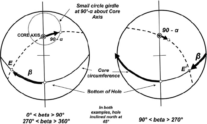
Fig. D.1 Using a stereonet to plot the pole to a plane from measured alpha (α) and beta (β) angles
in drill core. See text for a detailed description of the method
Step 2: Plot the two principal reference planes of the core onto a stereonet
overlay. These are:
1. The vertical plane passing through the core axis. This is the straight line
through CA and the centre of the net.
2. The circumference plane (the plane normal to the core axis). This is the
great circle girdle at 90
◦
to CA.
Where these two reference planes meet is point BOH. This is the point
from which the angle beta was measured. Initially, in order to understand
the procedure, it will be helpful to trace the reference planes, and mark
point BOH, onto the net overlay. However, with practice this will be found
unnecessary.
Step 3: Using the printed graticules of the net, count off the measured angle
beta around the great circle representing the circumference plane. Make the
measurement in a clockwise direction from the BOH point. When you reach
the net circumference (as will happen if β is ≥ 90
◦
), continue to count off the
degrees above 90
◦
in a clockwise direction along the same great circle, but
from the diametrically opposite point of the net. The point reached is marked
on to the overlay as either E or E
I
.
If the beta angle lies between 0 and 89
◦
, or between 271 and 360
◦
, then
the point marked on to the net is E. If beta lies between 91 and 269
◦
, then
point E
I
is plotted on the net. In the special case where beta is exactly 90 or
Appendix D 213
270
◦
then both E and E
I
will plot on the net, at diametrically opposite points
of its circumference.
Step 4: By rotating the overlay over the stereonet, locate the great circle that
contains the labelled points CA and E (or E
I
). Only one great circle will be
found which passes through the two points. Trace this onto the overlay.
Step 5: Measure the angle 90–α by counting off degrees along the great circle
marked on to the overlay at Step 4. Begin the measurement from the point
CA in the direction away from point E. If point E
I
rather than E appears on
the net, then the angle 90–α must be plotted from point CA towards the point
E
I
. If both E and E
I
appear on the net, then either construction will do. Once
the new point is located, mark and label it “P”. P is the pole to the original
planar structure measured in the core.
Step 6: From point P, read off the orientation of the structure in whatever format
is desired, for example as strike and dip, dip and dip direction or apparent dip
on drill section.
D.2 The Solution for Linear Structures
If a penetrative lineation has been measured using the internal core angles gamma
(γ) and delta (δ), it is possible to calculate trend and plunge using a stereonet. Here
is how it is done:
The step-by-step procedure for determining the trend and plunge of a penetrative
lineation is the same as that for a plane as far as Step 3 above. In Step 3, the measured
delta angle (δ) is used to plot the point T or T
I
in much the same way as the point
EorE
I
was located for a measured plane using beta. From this point proceed as
follows (refer to Fig. D.2):
Step 4: By rotating the overlay over the stereonet, locate the great circle girdle
which contains the labelled points CA and T (or T
I
). Only one great circle
will be found which passes through these points – this represents the plane
containing the core axis and the lineation.
Step 5: Measure the angle gamma (γ) by counting off the degrees along the
great circle plotted on to the overlay at Step 4. Begin from CA and measure
the angle towards point T. If T
I
rather than T is on the net, measure gamma
from CA in the direction away from T
I
. If both T and T
I
appear on the net,
then either construction will do. Once the new point is located, mark and
label it L. L is the plot of the lineation measured in the core. The trend and
plunge can now be simply read from the stereonet.
An alternative method of determining the lineation can be used where the orien-
tation of the surface containing the lineation has also been determined. For example,
where a lineation is exposed on the surface of a plane along which the core has been
broken, the plane can be measured by its α and β angles, and the lineation by its δ
214 Appendix D
Core
circumference
(a) (b)
Core
Axis
Bottom of
Hole
T
δ
γ
L
Cor e
Axis
T
δ
L
PITCH
Plane containing
lineation
Bottom o
f
Hole
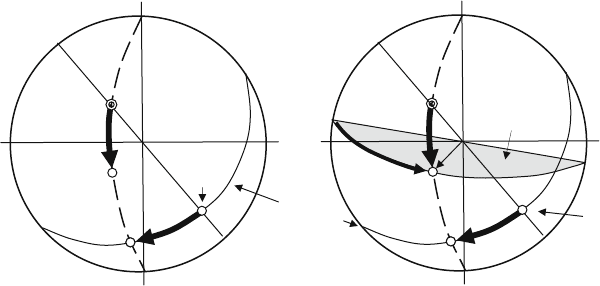
Fig. D.2 (a) Using a stereonet to determine the trend and plunge of a penetrative lineation from
measured gamma (γ) and delta (δ) angles in drill core. See text for a detailed description of the
method. (b) Using a stereonet to determine the trend and plunge of a lineation using the angle δ
and the orientation of the containing surface. See text for a detailed description of the method
angle. These three angles are sufficient to define both structures. To determine the
attitude of the lineation, proceed as follows (Fig. D.2):
Step 1: Plot the pole to the plane on the stereonet as described above.
Step 2: Trace the great circle representing the plane onto the net.
Step 3: Use angle δ to plot point T (or T
I
) as described above
Step 4: Locate the great circle girdle containing T (or T
I
)
Step 5: L lies at the intersection of the two great circle girdles.
Appendix E
Practical Field Techniques
E.1 Choosing the Right Compass
Great precision is not generally necessary when measuring geological structures
in the field and most available geological compasses will do the job adequately.
However, when choosing a compass for field work, look for the following features:
• An efficient damping system for the compass needle. An oil-filled compass
provides the most efficient type of damping system.
• An adjustable compass card which can be set to compensate for magnetic
declination (see below) or the orientation of a local grid.
• A compact and lightweight body.
• An ability to take measurements on small or inaccessible surfaces, including
underlays. This can be an important requirement in mine mapping.
• An ability to take accurate survey bearings.
• Not too expensive.
Needless to say, no single geological compass currently available meets all
these requirements. In particular, geological compasses are generally not sufficiently
accurate for taking the bearings necessary in geographical surveying. To solve this
problem, the author carries two compasses in the field: a general-purpose geolog-
ical compass (a Brunton
TM
or a Silva
TM
), and a lightweight, compact, specialist
compass designed for taking bearings (a Suunto
TM
).
E.2 Understanding Your Compass
Compass needles work by aligning themselves with the lines of force of the earth’s
magnetic field, which, as a first approximation and over most of the earth’s surface,
trend N–S. The magnetic field is centred on the north and south magnetic poles
which are located several hundred kilometres from the geographic poles around
which the earth rotates. In addition, the position at surface of the magnetic poles
is not fixed, but moves slowly and irregularly at a rate of tens of kilometres per
215

216 Appendix E
year. Magnetic compasses thus record a magnetic north direction (N
M
) rather than
a true north (N
T
) direction. In tropical to mid latitude areas magnetic north may
lie between 0 and 20
◦
to the east or west of true north. However, the difference
increases markedly in high latitudes with approach to the north and south magnetic
poles. The difference between True North and Magnetic North at any given position
on the earth’s surface is called the magnetic declination.
The magnetic declination for any area is usually given in the legend of a pub-
lished topographic or geological map as a rose diagram accompanied by a number
in degrees. For example, a declination of 10
◦
E(or+10
◦
) indicates that, for the area
of the map, Magnetic North lies 10
◦
east of True North. A declination of 10
◦
W
(or –10
◦
) indicates that Magnetic North lies 10
◦
west of True North. In addition to
declination, the map will also provide a date of publication and a statement setting
out the rate of annual variation, or drift, in the declination. In most places the annual
drift is measured in fractions of a degree per year and can generally be ignored
unless the map you are using is many decades old.
You can make use of the following Table E.1 to convert from True North to
Magnetic North, and vice versa. In the table, δ is the amount of magnetic declination.
Compasses with a rotatable compass card (known as a bezel) such as the
Brunton
TM
or the Silva
TM
, allow these corrections to be set on the compass s o that
the compass scale will automatically read true north or magnetic north as required.
A similar correction can be made on these compasses to enable them to directly give
bearings on a locally established grid.
The magnetic lines of force are horizontal at the equator but dip at ever more
steep angles as the north and south magnetic poles are approached. The north-
pointing end of the compass needle thus tends to dip below the horizontal in
the northern hemisphere and above the horizontal in the southern hemisphere.
Compass makers compensate for this effect by weighting the needle to enable
it to lie approximately horizontal in mid-latitude areas. Different compasses are
manufactured for northern and southern hemispheres. For this reason, compasses
designed for the northern hemisphere are difficult or impossible to use in the south-
ern hemisphere and vice versa. Mid-latitude compasses work adequately in tropical
areas but may need to be tilted slightly to keep the needle swinging freely in the
compass case.
Table E.1 Converting true north to magnetic north and vice versa
Declination
To convert true north
to magnetic north
To convert magnetic north
to true north
– δ
◦
or W declination
a
Subtract δ
◦
from N
T
bearing Add δ
◦
to N
M
bearing
+ δ
◦
or E declination
b
Add δ
◦
to N
T
bearing Subtract δ
◦
from M
N
bearing
a
That is, magnetic north lies to the west of true north.
b
That is, magnetic north lies to the east of true north.
Appendix E 217
E.3 Measuring the Strike and Dip of Planes
This is one of the basic skills which every geologist is taught, but it may be
worthwhile setting down a few helpful tips.
Taking a measurement by placing a compass along a rock face – although this
may be necessary if this is the only surface available – only measures the portion of
the surface in contact with the instrument. Wherever possible, a more representative
strike should be obtained by sighting along a line of outcrop thus averaging the
strike over that distance (Fig. E.1). Be careful, when doing this, to ensure that the
line of sight is horizontal (however, any tilt on the compass sufficient to make the
strike measurement substantially in error will also trap the compass needle against
the face glass and so alert you to the problem).
Similarly, where a dipping bed is exposed on a vertical or near-vertical surface,
the most representative dip is obtained by sighting the clinometer on that surface
from a distance and so averaging the dip over the area of the outcrop (Figs. E.2 and
E.3). This technique is only accurate if the sighting is made while looking along
strike – otherwise an apparent dip is obtained. An apparent dip is always less than
the true dip.
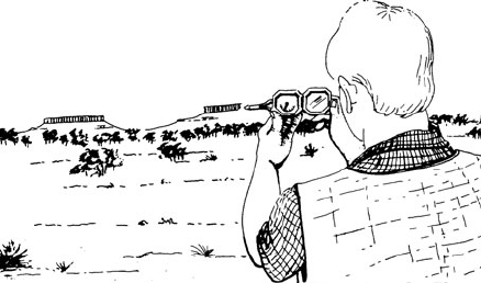
Fig. E.1 Sighting with a
compass along a line of
outcrop to obtain an averaged
strike direction. Caution – the
line of sight must be
horizontal
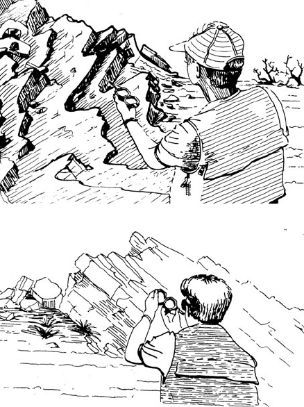
Fig. E.2 Sighting with a
geological compass along the
strike of an outcrop to obtain
the average dip of beds
exposed on vertical surfaces.
Caution, the line of sight
must be parallel to strike
218 Appendix E
Fig. E.3 Measuring the dip
of beds on a distant mesa by
sighting along strike
When measuring a plane with a small surface area, the plane can be extended to
permit measurement by laying the surface of a notebook or map-board against the
surface and then measuring the attitude of the extension plane so formed.
Determining the dip direction of small or awkwardly positioned planes can be
difficult. A trickle of water down the surface of the plane can often solve this prob-
lem – heroic measures are not necessary here if a small dropper bottle of coloured
liquid is kept handy in the field kit.
When measuring orientation on the underside of a plane, particularly when look-
ing up at that plane (a problem that often arises in mine mapping), the use of a
Silva
TM
geological compass is invaluable as its compass needle can be sighted
from below as well as from above, and the bezel can be rotated to record the posi-
tion of the needle. For that reason, the Silva
TM
has some advantages over other
types of compass for mine mapping. Some specialist geological compasses (such
as the Freiberg
TM
geologists’ compass or the Cocla
TM
compass manufactured by
Breithaupt Kassel) will also measure on an underlay, but these compasses are larger
and often cannot fit into a confined space. They are also much more expensive
instruments.
Some recent models of geological compass, such as the Tectronic made by
Breithaupt Kassel, offer automatic electronic measurement of dip and dip direc-
tion. The measurements can stored in the instrument memory against keyed-in code
numbers, displayed on a liquid crystal display and downloaded to computer. This
instrument would be valuable in applications where large numbers of orientation
measurements need to be taken (e.g. some specialist structural or geotechnical appli-
cations), but they are relatively expensive; for most applications, the traditional
low-tech geologists’ compass will do everything that the field geologist requires.
E.4 Measuring the Trend and Plunge of Lineations
Measurable linear features encountered in rocks can be fold axes, elongate boudins,
mullions, preferred elongations of minerals or mineral aggregates, elongated clasts,
slickenlines or the intersection of two surfaces (such as bedding and cleavage). All
Appendix E 219
these will be collectively referred to here as linears. Linears are important and pro-
vide vital clues towards unravelling geology and mineralization in deformed rocks.
Linears are easy to measure and record and this should be done routinely when field
mapping or logging drill core.
In the author’s experience, many geologists are not quite sure how to measure
and record lineations, hence the following detailed description. It is based on the
use of a Brunton
TM
compass but other geological compasses can be used. However,
the slotted and horizontally extendable sight on the Brunton makes the procedure
particularly easy.
Linear features within a rock are defined geometrically either by their trend and
plunge, or, if they lie upon the surface of a plane, by their pitch upon that plane.
These terms are defined on the block diagram of Fig. E.4. The pitch will only define
the absolute orientation of a linear if the attitude of the plane on which the pitch is
measured is also known. Given either of the two sets of measurements, the other can
be calculated mathematically or by stereo-net. For general mapping purposes it is
usually more useful to measure and record the trend and plunge of the structure, but
in some situations, particularly when working in mines, it may be easier to measure
pitch.
50°
55°
330 °
NORTH
72°
Trend of
lineation
Strike of
surface
Dip of
surface
Plunge of
lineation
Pitch of
lineation on
surface
VERTICAL
PLANE
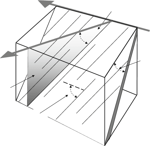
Fig. E.4 Block diagram defining the strike and dip of a surface; the trend and plunge of a lineation
and the pitch of a lineation on a surface

220 Appendix E
Fig. E.5 Measuring the trend
of a lineation with a
Brunton
TM
compass
The recommended field procedure for measuring lineations is as follows:
• If the linear to be measured is not clear in the rock, mark it with a felt-tip pen, or
lay a pencil along it, before making the measurement.
• Hold an open Brunton compass horizontally
10
above the linear with the slotted
sighting bar horizontally extended (Fig. E.5). Sight vertically down on to the
linear through the slot in the sighter, rotating the compass in the horizontal plane
so that sighter bar and linear are aligned. Use the thickness of the sighter bar to
judge whether the view is vertical down on to the linear (when the view is f rom
Fig. E.6 Measuring the
plunge of a lineation with a
Brunton
TM
compass
10
The Freiberg structural geology compass will measure trend and plunge of lineation directly.