Marjoribanks R. Geological Methods in Mineral Exploration and Mining
Подождите немного. Документ загружается.

Appendix B 201
α = 90 °
α = 38
°
α = 63
°
α = 47
°
α = 24
°
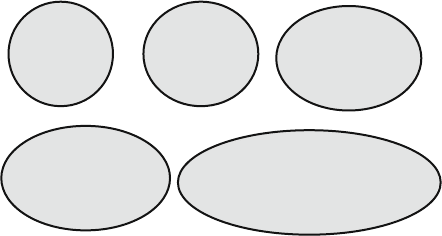
Fig. B.13 Examples of intersection ellipses for planes at various angles to the core axis. As the α
angle between the core axis and the plane increases, so the intersection ellipse approaches a circle.
Defining the position of the ellipse long axis on the surface of the core (necessary to measure angle
beta) with any accuracy becomes difficult for any α ≥ 55
◦
, and all but impossible for α ≥ 65
◦
.For
this reason, it is recommended that the internal core angle method for calculating the attitude of
planes not be used where α ≥ 65
◦
at a low angle to the core axis (that is, the alpha angle is low) because this geometry
gives an elongate intersection ellipse with well-defined inflection points. However as
alpha approaches 90
◦
, so the intersection ellipse approaches a circle and E becomes
increasingly harder to define (Fig. B.13). For this reason, when making beta mea-
surements, progressively increasing errors will occur for all planes with α >50
◦
.
If the planes being measured are very well defined, regular and close spaced, an
acceptable beta number might still be obtainable but in all cases, where α >65
◦
,it
is recommended that the method not be used.
B.3.5 Discussion on the Best Measuring Technique
For most applications, it is recommended that a core frame be used to measure the
orientation of structures. The main reason is that the frame permits direct visual-
isation of structures in their original orientation, and measurement of attitudes in
geologically meaningful terms at the time of logging. If the method of measuring
internal core angles is chosen, then a core frame must also be available in order to
measure planes with high alpha angles. In addition, a core frame is the only way in
which non-penetrative linear structures – such as fold axes – can be measured. In
any case, where the internal core angle method is used, it is recommended that a
stereonet be employed for direct reduction of the data, at the core tray, as the mea-
surements are being made with direct entry of the strike/dip (or trend/plunge) on to
the log sheet.
The internal core angle technique does however offer some advantages:
• Measuring alpha/beta angles is much faster than using a core frame.
• If the requirement is to make a very large number of measurements of a set
of planar structures, whose identification and significance are otherwise well
202 Appendix B
understood, with a view to a statistical treatment of the results, then the internal
core angle technique, with computer processing of the results provides the quick-
est and most effective option. This situation can arise, for example, in a mine
application, in geotechnical logging or in the advanced infill drilling stages of
prospect exploration. In this case, the internal angles would normally be entered
directly onto a spreadsheet type of log form (or directly into a portable computer)
for subsequent processing. Presentation will usually be in the form of a com-
puter generated section or map, a s tereonet pole figure or a histogram. However,
even for these applications, the inherent limitations on the use of this method, for
planes with particular orientations, need to be borne in mind.
• Measuring internal core angles may be the most efficient method of record-
ing structure attitude onto analytical spread-sheet type logs during the advanced
drilling stages of a prospect.
B.3.6 Plotting Structure Measurements on Drill Section
Once the orientation of a surface has been measured it can be plotted on to the
drill section using a short line to represent to represent the trace of the surface, as
described in detail in Sect. 7.7. If the hole is at right angles to the strike of the surface
then the trace of the surface will be a single line plotted at the measured dip.
In the general case where the hole is not at right angles to the strike of the surface,
the trace of the surface on a section will be an apparent dip. Apparent dips are
always less than true dips. Very shallow dipping or very steep dipping surfaces are
least sensitive to the direction of the section on which they are shown; moderately
dipping surfaces are most sensitive. In order to plot a surface on a drill section the
apparent dip has to be calculated. There are four methods available for calculating
apparent dips (Travis and Lamar, 1987).
1. By using the formula below, where A = apparent dip, D = true dip and X = the
angle between the section direction and the strike of the surface:
tan A = tan D × sin X
Most mining/exploration software programs will automatically calculate
apparent dips using the above formula and plot them onto drill sections. Use
of a trigonometric formula provides an exact answer for the apparent dip that is
limited only by the accuracy of the input numbers D and X.
2. By using a table of apparent dips (Table B.1). This table was constructed using
the above formulae and sets out the apparent dip of any surface for angles of
true dip (D) and different sectional orientations (X) in 5
◦
increments. For most
measured true dips, Table B.1 will allow estimation of the apparent dip to 2–3
◦
.

Appendix B 203
Table B.1 Table for converting between true and apparent dips
Angle between direction of strike and direction of section
90 85 80 75 70 65 60 55 50 45 40 35 30 25 20 15 10 5 0
True dip
◦
Apparent dip
◦
0 000000000000000000
5 555444443322211000
10 101010999887665433210
15 15 15 14 14 14 13 12 12 10 10 9 8 6 5 4 3 1 0
20 20 20 19 19 18 18 17 16 14 13 12 10 9 7 5 4 2 0
25 25 25 24 24 23 22 21 20 18 17 15 13 11 9 7 5 2 0
30 30 30 29 28 28 27 25 24 22 20 18 16 14 11 9 6 3 0
35 35 35 34 33 32 31 30 28 26 24 22 19 16 13 10 7 4 0
40 40 40 39 38 37 36 35 33 31 28 26 23 20 16 12 8 4 0
45 45 45 44 43 42 41 39 37 35 33 30 27 23 19 15 10 5 0
50 50 50 49 48 47 46 44 42 40 37 34 31 27 22 17 12 6 0
55 55 55 54 53 52 51 49 48 45 43 39 36 31 26 20 14 7 0
60 60 60 59 58 58 56 55 53 51 48 45 41 36 30 24 17 9 0
65 65 65 64 64 63 62 60 59 57 54 51 46 42 36 29 20 11 0
70 70 70 69 69 69 68 67 65 63 60 58 54 49 43 35 25 13 0
75 75 75 74 74 74 73 72 71 69 67 65 62 58 52 44 33 18 0
80 80 80 80 79 79 78 78 77 76 75 73 71 67 63 56 45 26 0
85 85 85 85 85 84 84 84 83 83 82 81 80 78 76 71 63 45 0
90 90 90 90 90 90 90 90 90 90 90 90 90 90 90 90 90 90 0
Although this is sufficiently accurate for most purposes, for true dips between
30 and 60
◦
and sections oriented at less than 50
◦
to the strike of the surface,
estimation from the table could produce errors of greater than 3
◦
. In these cases
it probably better to use one of the other methods listed here.
3. By using a specially designed plastic protractor/calculator. This simple device
(available commercially) is a nomogram
6
which allows quick calculation of
apparent dips to an accuracy of 1–2
◦
. The tool was first described by Palmer
(1918) and detailed in its modern form by Travis (1964). A plastic version is
available commercially.
4. By using a stereonet. This is the procedure that the author recommends. It is
probably one of the simplest stereonet calculations that can be made and takes
about 10 s. Accuracy, for all orientations, is 1–2
◦
. A worked example of an
apparent dip calculation using a stereonet is given in Fig. B.14.
6
A nomogram is a physical device that provides an analog graphical way of calculating a
mathematical formula. A slide-rule is a nomogram. So is a stereonet.

204 Appendix B
Apparent dip for
section at 30
°
to
strike
Apparent dip for
section at 60
° to
strike
True Dip – 90
°
to strike
31°
46°
50°
N
plane dipping
50° west
Fig. B.14 How to use a stereonet to calculate an apparent dip. On the stereonet, planes plot as
great circles. Vertical planes (drill sections) are straight lines passing through the origin. In this
example, a bedding plane dipping 50
◦
Wisshown(shaded surface). The point where the straight
line representing any given drill section intersects the bed is the apparent dip of the bed on that
section and its value can be read off from the graticules of the net. The procedure to calculate an
apparent dip takes about 10 s
References
Annels AE, Hellewell EG (1988) The orientation of bedding, veins and joints in core; a new method
and case history. Int J Min Geol Eng 5(3):307–320
Goodman RE (1976) Methods in geological engineering in discontinuous rocks. West Group,
Eagan, MN, 484p
Goodman RE (1980) Introduction to rock mechanics. Wiley, New York, NY, 478p
Hoeks E, Diederichs M (1989) Dips version 2.0 users manual. Advanced Version, 117p
Marjoribanks RW (2007) Structural logging of drill core. Handbook 5, Australian Institute of
Geoscientists, Perth, WA, 68p
Palmer HS (1918) Method for determining the depth and thickness of strata and the projection of
dip. USGS Professional Paper 120-G. GPO, Washington, DC, 123–128
Reedman JH (1979) Techniques in mineral exploration. Applied Science Publishers, London, 533p
Roxtrom E (1961) A new core orientation device. Econ Geol 56:1310–1313
Travis RB (1964) Apparent dip calculator. AAPG Bull 48(4):503–504
Travis RB, Lamar DL (1987) Apparent dip methods. J Geol Educ 35(3):152–154
Vearncombe J, Vearncombe S (1998) Structural data from drill core. In: Davis B, Ho SE (eds) More
meaningful data in the mining industry, vol 22. Bulletin/Australian Institute of Geoscientists,
Perth, WA, 67–82
Zimmer PW (1963) Orientation of small diameter core. Econ Geol 58:1313–1325

Appendix C
Calculating Strike and Dip from Multiple
Diamond Drill Holes
C.1 The Three Point Problem
The need to determine the s trike and dip of a planar structure from a number of
drill intersections is one that occurs very frequently – this is often called the three-
point problem
7
and every geologist should be familiar with the simple solutions to
it (Marjoribanks, 2007).
Where a number of adjacent holes are drilled into a prospect, preparing com-
posite drill sections and correlating sequences between adjacent holes can enable
details of the large-scale structure to be deduced.
The attitude of any plane is fully defined if the position in 3D space of three
or more points on that surface is known. Where three separate holes intersect the
same marker bed, they provide three points of known position on that surface. From
the intercept data, there are two ways of calculating the strike and dip. The first
makes use of structure contours. The second involves the use of a stereonet. In the
presentation of the solutions below, it is assumed that the bed to be measured has
the same attitude in all three holes.
C.2 Solution Using Structure Contours
Proceed as follows (see Fig. C.1):
Step 1: Determine the three-dimensional coordinates (i.e. northing, easting and
height above a common datum) of each intersection of the marker bed in the
holes.
Step 2: Plot the three bed intersection points on a map using the northing and east-
ing coordinates for each intersection. Write the depth (often called the Relative
Level, or RL) of the intersection beside each point.
Step 3: Draw a line joining any two pairs of intersections on the map. The height
of the intersection at the beginning and the end of the line is already marked.
7
Presumably in conscious or subconscious reference to Sherlock Holmes’ 3-pipe problem.
205
206 Appendix C
A 800 m
C 650 m
B 400
m
A 800 m
C 650
m
B 400
m
100
m
100
m
700 m
700m
600
m
700
m
500m
500
m
Structure contours
45°
PLAN
VIEW
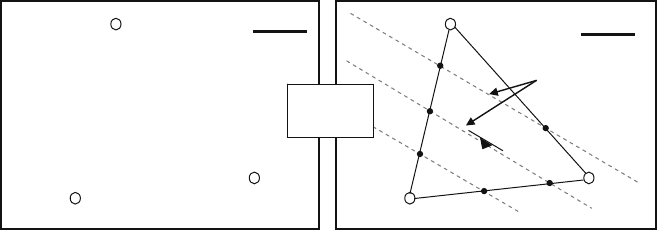
Fig. C.1 Using structure contours to determine the strike and dip of a planar surface intersected in
three drill holes. On the map at left, three drill holes have intercepted a common bed. The intercepts
have been projected vertically onto the plan and labelled with their height above a common datum.
On the right hand map, by constructing lines between each plotted intersection, the position of
different heights along the lines can be scaled off. Structure contour lines (dashed) for the bed are
constructed by joining points of equal height. These lines define the strike of the surface. From
the map scale, the horizontal distance between lines of known height can be measured – simple
trigonometry then allows the dip to be calculated
Using a ruler, scale off along the line to identify the positions of all interme-
diate depths along the line. Identify and mark even-number depth divisions on
the line. Carry out this same procedure for the other two pairs of lines, marking
on to the lines the same set of depth divisions as were marked on the first line.
Step 4: Draw the lines joining points of equal depth on the surface. These repre-
sent horizontal lines on the bed and they mark its strike. This strike can then
be measured on the map using a protractor. The map projection of the trace of
a horizontal line on a surface is known as a structure contour.
Step 5: Use the map scale to measure the horizontal distance (h) between two
widely spaced contour lines. Since the vertical separation (v) of the contour
lines is known, the dip of the surface (d) can be calculated according to the
formula:
tan d = v/h
C.3 Solution Using a Stereonet
Proceed as follows (see Fig. C.2):
Step 1: Determine the absolute position coordinates (i.e. northing, easting and
height above a common datum) of each intersection of the marker bed in the
three holes.
Step 2: Plot the three intersection points on a map. Use a protractor to measure
the trend (bearing) of the lines joining the three points. Use a ruler to scale off
Appendix C 207
N
27
51
35
223°
162°
283°
132° strike o
f
bed
Apparent dip 1
27° to 283°
Apparent dip 2
51° to 223°
Apparent dip 3
35° to 162°
Apparent dip 1
27° to 283°
Apparent dip 2
51° to 223°
Apparent dip 3
35° to 162°
DDH 346
1264m
DDH 349 1133 m
DDH 397
1208 m
PLAN
Fig. C.2 Using a stereonet to determine the strike and dip of planar surface intersected in three
drill holes. The intercepts are projected onto a plan and labelled with the height of each intersection
above a common datum. The line that joins any pair of intersections is an apparent dip on the bed
and can be described by its dip and dip direction. Where v is the vertical height difference between
each pair of intersections, and h their horizontal separation, the apparent dip (a) can be calculated
using Tan a = v/h. The dip direction is measured directly from the plan with a protractor. Three
apparent dips can be calculated in this way. On the stereonet, the three apparent dips plot as three
points. The net overlay is rotated to bring the points to lie on a great circle girdle. This girdle is the
plot of the bed and its strike and (true) dip can be easily read off. (Actually, only 2 apparent dips
are necessary to define the surface, but using a third line provides extra accuracy.)

208 Appendix C
the horizontal distance between the points. Knowing the horizontal and eleva-
tion difference between any pairs of intersection points, simple trigonometric
formulae (see Step 5 above) will provide the angle of plunge (the angle which
the line makes with the horizontal, measured in the vertical plane) for the line
that joins any two pairs of points.
Step 3: We have now calculated the trend and plunge of three lines lying on the
surface of the marker bed. Mark these lines on to a stereonet overlay. They
plot as three points, as shown on Fig. C.2.
Step 4: Rotate the overlay so as to bring the three points to lie on a common great
circle. Only one great circle will satisfy all three points.
8
This great circle
represents the trace of the bed that was intersected by the drill holes.
Step 5: From the net, read off the strike and dip of the surface (or dip and dip
direction, or apparent dip on any given drill section).
C.4 An Elegant Solution to Determining the Attitude of Planes
in Non-oriented Core
Where there is no single marker bed that can be correlated between adjacent holes,
it is sometimes still possible to determine the orientation of a set of parallel surfaces
(such as bedding planes, a cleavage, or a vein set) provided that the surfaces have
been cored by a minimum of three nonparallel drill holes (Bucher, 1943; Mead,
1921). The same technique can even be extended to a single hole, provided that
the hole has sufficient deviation along its length for the differently oriented sectors
of the same hole to be considered in the same way as three separate holes (Laing,
1977).
The stereonet plot of Fig. C.3 illustrates three adjacent but non-parallel angle
holes that have intersected the same set of parallel, planar quartz veinlets. None of
the core is oriented, but the average alpha (α) angle between the veins and the core
axis has been measured in each hole: it is 10
◦
in Hole 1, 56
◦
in Hole 2 and 50
◦
in
Hole 3.
On a stereonet, the orientation (azimuth and inclination) of a drill hole plots as a
point. The holes are the points labelled Hole 1, Hole 2 and Hole 3 on Fig. C.3.
When plotting planes on a stereonet it is always much easier to work with the
pole
9
to the plane rather than the plane itself. If a plane makes an angle α with the
core axis, then the pole to the plane makes an angle of 90–α to the core axis, as
illustrated in Fig. C.4.
Let us consider Hole 1. Angle α and hence angle 90–α for the veins are known.
Because the core is not oriented, the poles to the veins could lie anywhere within
the range of orientations that is produced as the core is rotated one complete circle
8
Actually, on a stereonet, only two points are needed to define a plane. The use of a third point
adds accuracy and provides for error checking.
9
The pole to a plane is the line at right angles, or normal, to the plane. By plotting the pole, the
attitude of a plane can be represented on a stereonet by a single point.

Appendix C 209
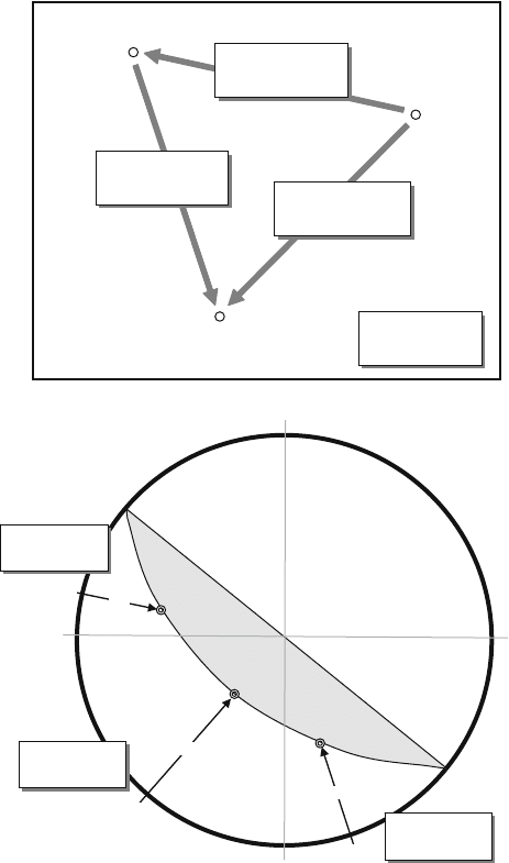
Fig. C.3 If a set of parallel, planar surfaces (such as a penetrative cleavage or a vein swarm) is
intersected by three non-parallel, non-oriented diamond drill holes, it is possible to use a stereonet
to calculate the strike and dip. All that is necessary is an average value for the alpha (α) angle made
by the structure in each drill hole. For a description of the method, see text
E
I
E
α
90 – α
Core Axis
Pole to
surface
Fig. C.4 The angular
relationship of t he alpha
angle (α) to the pole (i.e. the
normal) of a surface
intersected in drill core
210 Appendix C
about its long axis. This range defines a cone, centred on the core axis, with an apical
angle of 2 × (90–α). That is all we can tell from one hole, but this information can
be shown on the stereonet, because a cone centred on a drill hole plots as a small
circle girdle around that hole. In Hole 1, 90–α is 80
◦
. The vein set in Hole 1 can
therefore be represented by a small circle girdle at an angle of 80
◦
to the hole plot.
Now the same procedure is carried out for Hole 2 by drawing a small circle at
90–α (34
◦
) to the plot of that hole on the net. The small circle about Hole 1 and
the small circle about Hole 2 intersect at two points – these points represent two
possible orientations for the vein set. Now we draw the third small circle about
Hole 3. We now have three small circle girdles, centred about each of the three
drill holes, on the stereonet overlay. Since the assumption behind this procedure
is that all measurements are of the one vein set with a constant orientation, the
single point (P) where the three small girdles intersect must represent the pole to
the one orientation that common to all three holes. This must represent the unique
attitude of the common vein set seen in the holes. Of course, with a real set of
measurements it is highly unlikely that the three lines would meet at a single point.
Rather, the intersecting lines will define a triangle whose size reflects the accuracy
of the measurements (and the assumptions made that we are dealing with a single
parallel set of surfaces). The true pole position (if there is one) will lie somewhere
within this triangle of error.
From the point P, the strike and dip (or dip and dip direction, or apparent dip on
drill section) of the vein set can be simply read off from the net.
References
Bucher WH (1943) Dip and strike for three not parallel drill holes lacking key beds. Econ Geol
38:648–657
Laing WP (1977) Structural interpretation of drill core from folded and cleaved rocks. Econ Geol
72:671–685
Marjoribanks RW (2007) Structural logging of drill core. Handbook 5. Australian Institute of
Geoscientists, Perth, WA, 68p
Mead WJ (1921) Determination of the attitude of concealed bedding formations by diamond
drilling. Econ Geol 21:37–47