Lyons W.C. (ed.). Standard handbook of petroleum and natural gas engineering.2001- Volume 1
Подождите немного. Документ загружается.


Dynamics
165
Note that
e
is defined in terms of the components
of
the velocities, not the vector
velocities, whereas the momentum balance is defined in terms of the vector
velocities.
To
solve Equations
2-32
and
2-33
when all the velocities are not colinear,
one writes the momentum balances along the principal axes and solves the resulting
equations simultaneously.
For purely elastic impacts, e
=
1, and for purely plastic impacts, e
=
0.
For elasto-
plastic impacts, e lies between zero and one and is a function
of
both the material
properties and the velocity of impact.
Example
2-1
0
Sphere
1
weighs 1 Ib and is traveling at
2
ft/s in the positive x direction when
it
strikes sphere
2,
weighing
5
lb and traveling in the negative x direction at 1 ft/s.
What will be the final velocity of the system if the collision is (a) plastic, or (b)
Elastoplastic with e
=
0.5!
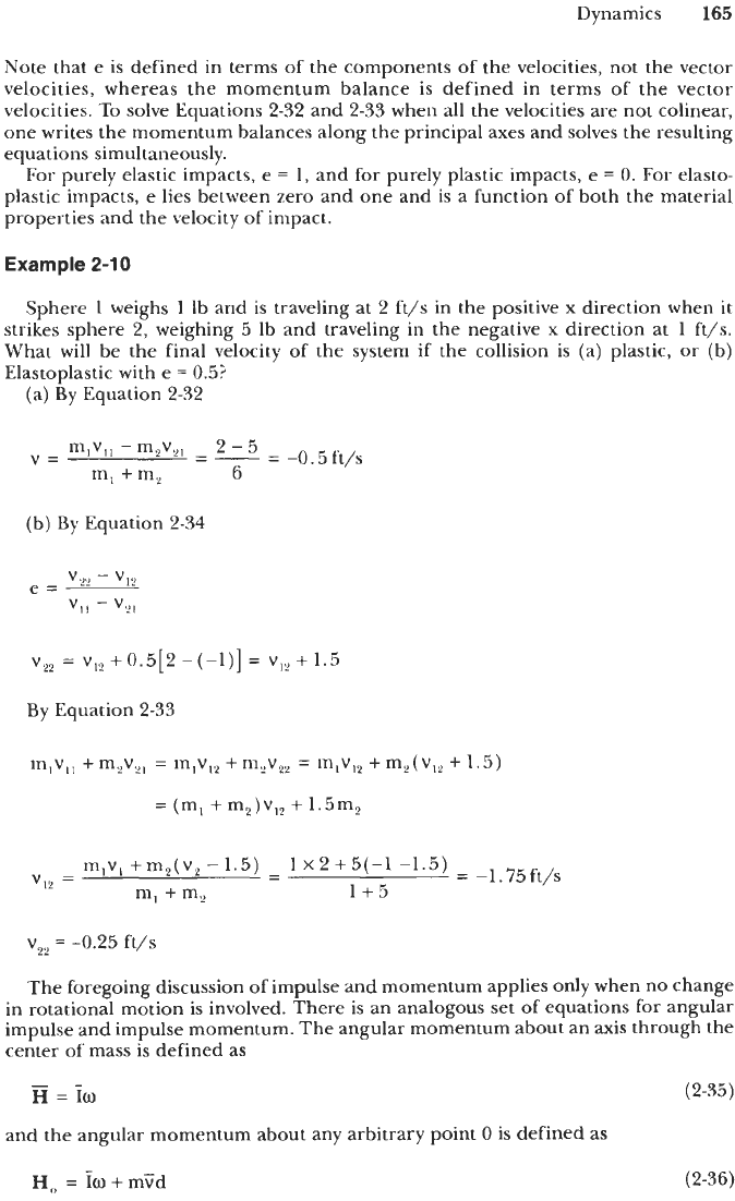
(a) By Equation 2-32
-
-0.5 ft/s
mlVll
-
m,V,,
-
2
-
5
V=
m, +my
6
(b) By Equation
2-34
v,,
=
vI2
+
0.5[2
-
(-1)]
=
v,,
+
1.5
By Equation
2-33
mlvl,
+
m,v,,
=
m,vI2
+
m,v,,
=
m,vl2
+
m,(V,,
+
1.5)
=
(m,
+
m2)v,,
+
1.5m2
mlv, +m,(v,
-
1.5)
1
x
2
+5(-1
-1.5)
v,,
=
- -
=
-1.75ft/s
m, +my 1+5
v,,
=
-0.25 ft/s
The foregoing discussion of impulse and momentum applies only when no change
in rotational motion is involved. There is an analogous set of equations for angular
impulse and impulse momentum. The angular momentum about an axis through the
center of mass
is
defined as
-
H
=
f~
and the angular momentum about any arbitrary point
0
is defined as
(2-35)
H,
=
lo
+
mGd
(2-36)

166
General Engineering and Science
where
V
is the velocity of the center
of
mass and d is the perpendicular distance
between the vector
v
and the point
0.
And if
0
is a fixed axis or instantaneous center
of zero velocity, then
H,
=
I,o
(2-37)
Likewise, the angular impulse is defined as
I
M,dt
=
AH,,
(2-38)
In collisions, angular momentum, like linear momentum, is conserved.
Conservation
of
Energy
In a rigid-body system, energy is conserved in the sense that the net change in
mechanical energy must be equal to the net work done on the system.
U
=
AT
+
AVg
+
AVe
(2-39)
U
is the net work done on the system and is defined as the sum of the work done
by external forces and external moments.
U
=jF*ds+jM*dB
(2-40)
The work of the force
F
is
positive if it acts in the direction of the displacement ds,
and the work of the moment M is positive if it acts in the direction of rotation de.
AT is the change in kinetic energy, made up of a change in linear kinetic energy
and rotational kinetic energy.
1
1-
2
2
AT
=
-m(C:-Vy)+-I(mt-of)
If the body in question has a fixed axis or an instantaneous center of zero velocity,
then Equation
2-41
can be simplified to
AVg is the net change in gravitational potential energy. This term is path
independent and depends only on the initial and final heights, h, and h, above some
arbitrary reference height with respect to the surface of the earth.
AVg
=
mg(h,
-
hi)
=
W(h,
-
h,)
(2-43)
AVe
is
the net change in elastic energy stored in a massless spring, due to extension
or compression (no spring is massless, but this assumption is reasonably accurate for
most engineering calculations).
1
2
AVe
=
-
k(X;
-
Xy)
(2-44)

Dynamics
167
The constant k, called the spring constant, represents the ratio of the force exerted
by the spring to
X,
its net compression or extension from the rest length.
Example 2-11
A 1-lb sphere is dropped from a height of
20
ft to strike a 2-ft long relaxed vertical
spring with a constant
of
100 lb/ft (see Figure
2-17).
What will be the velocity of the
sphere at a height of
2
ft when it strikes the spring? What will be the maximum
compression of the spring?
The sphere and the spring may be considered as a system in which no outside
forces or moments are acting. Thus the work term in Equation
2-39
is zero. Before
the collision with the spring,
AVe
=
0
also, and Equation
2-39
reduces to
AT
+
AVp
=
0
AVp
=
W(h,
-
hi)
which can be solved for the impact velocity.
Vf
=
34
ft/s
At full compression the velocity of the sphere is zero. Thus Equation
2-39
reduces to
AV?
+
AVg
=
0
I8
ft
Figure
2-17.
Diagram for Example
2-11.

168
General Engineering and Science
AVp
=
W(
h,
-
hi)
h,
=
L
-
X,
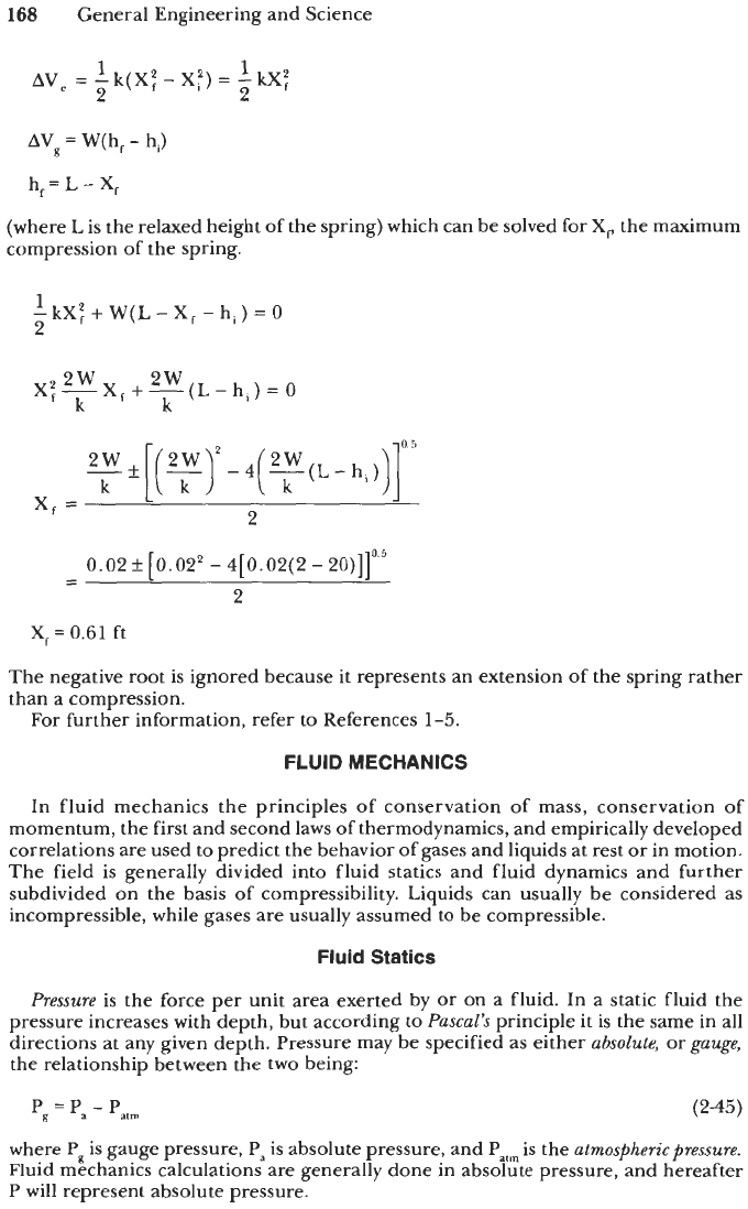
(where
L
is the relaxed height of the spring) which can be solved for
X,
the maximum
compression of the spring.
1
-kX:
2
+
W(L-
X,
-hi)
=
0
2w 2w
k k
X:-Xx,
+-(L-
h,)
=
0
-
0.02+[0.02*
-
4[0.02(2-20)]]0'5
-
2
X,
=
0.61
ft
The negative root is ignored because
it
represents an extension of the spring rather
than a compression.
For further information, refer to References
1-5.
FLUID MECHANICS
In fluid mechanics the principles
of
conservation of mass, conservation of
momentum, the first and second laws
of
thermodynamics, and empirically developed
correlations are used
to
predict the behavior of gases and liquids at rest or in motion.
The field is generally divided into fluid statics and fluid dynamics and further
subdivided on the basis of compressibility. Liquids can usually be considered as
incompressible, while gases are usually assumed to be compressible.
Fluid Statics
Pressure
is the force per unit area exerted by or on a fluid. In a static fluid the
pressure increases with depth, but according to
Pascal's
principle
it
is the same in all
directions at any given depth. Pressure may be specified as either
absolute,
or
gauge,
the relationship between the two being:
where Pp
is
gauge pressure,
Pa
is absolute pressure, and
Patm
is the
atmospheric pressure.
Fluid mechanics calculations are generally done in absolute pressure, and hereafter
P will represent absolute pressure.

Fluid Mechanics
169
The governing equation for the pressure within a fluid at any depth h is
dP
=
pgdh
(2-46)
where
p
is the fluid density in mass per unit volume, and g is the acceleration due
to
gravity. In engineering calculations it is often convenient to replace the quantity
pg
with
y,
the
specific weight,
which is a measure of the weight of the fluid per unit
volume.
If
y
can be considered to be constant, the fluid is said to be incompressible and
Equation
2-46
can be solved to yield
P
=
P,,
+
y(h
-
h,)
(2-47)
where h,) is some reference depth, h is depth increasing downward, and P, is the
pressure at h,. In a gas the specific weight of the fluid is a function of pressure and
temperature. The concept of an
ideal
or
perfect gas
as one in which the molecules
occupy no volume and the only intermolecular forces are due to intermolecular
collisions leads to the
ideal gas law:
PS
y=-
RT
(2-48)
where P is the absolute pressure in pounds per square foot,
T
is the temperature in
degrees Rankine,
S
is the specific gravity (the ratio of the density of the gas in
question
to
the density of air at standard conditions), and R is Boltzman's constant
(53.3
ft-lb/lb-OR). Under the assumption of an ideal gas at constant temperature,
Equation
2-46
can be solved to yield
(2-49)
If the gas behavior deviates markedly from ideal, the real gas law can be written as
Ps
y=-
ZRT
(2-50)
where
Z
is an empirical compressibility factor that accounts for nonideal behavior
(See Volume
2,
Chapter
5).
Substituting the real gas law into Equation
2-47
yields
ZT
S
-dP
=
-dh
P
R
(2-51)
Equation
2-51
can be integrated under the assumption that
Z
and
T
are constant to
yield Equation
2-52,
or, if extreme accuracy is required, it is necessary to account for
variations in
Z
and
T
and a numerical integration may be required.
(2-52)

170
General Engineering and Science
Example
2-12
Consider a 1,000-ft-deep hole. What will be the absolute pressure at the bottom
if (a) it is filled with pure water or (b) it is filled with air at a constant temperature
of 85"F?
(a)
P
=
P,
+
dh-h,)
h,
=
0
h
=
1,000
ft
y
=
62.4 lb/ft3
P
=
2,116.8
+
62.4(1,000
-
0)
=
64,516.8 lb/ft2
P
=
448 psi
(b)
s=l
Assume
z=l
T
=
85
+
460
=
545"R
(1'000-0)1
=
2,190.941b/ft2
P
=
2,116.8exp
1(
53.3)( 545)
1
P
=
15.21 psi
In a case where
Z
#
1, it is practical to assume
Z
=
1, perform Calculation (b), and
then, based on the resultant, estimate for
Pavg
=
(P
+
P,)/2, find the value of
Z,
and
repeat the calculation. Three iterations are generally sufficient. If
T
varies, it is usually
sufficiently accurate to use
an
estimate
of
Tavg
such
as
Tavg
=
(T
+
TJ2.
Fluid
Dynamics
When fluids are in motion, the
pressure
losses
may be determined through the
principle of conservation of energy. For slightly compressible fluids this leads to

Fluid Mechanics
171
Rrrnoulli
'F
equation
(Equation 2-53), which accounts for static and
dynarnzc.
pressure
loswr
(due to changes in velocity), but does not account for frictional pressure losseu,
energv losses due to heat transfer, or work done in an engine.
(2-53)
where
v,,
v2
=
velocity at points 1 and
2
g
=
the acceleration due to gravity
(See Figure 2-18.)
For flow in pipes and ducts, where frictional pressure losses are important, Equation
2-53 can he modified into
(2-54)
where
f
E
an empirical friction factor
v
=
the average velocity along the flow path
L
=
the length of the flow path
D
E
the hydraulic diameter, 2(flow area)/(wetted perimeter)
(See Figure 2-18.)
If
the fluid
is
highly compressible, Equation 2-53 must be further modified:
(2-55)
where
k
=
ratio of specific heats, cdc,; see Table 2-8.
(See Figure
2-18.)
Thefriction
factor
in Equations 2-54 and 2-55
is
a function of the
surface roughness
of
the pipe and the
Reynold's number.
Typical surface roughnesses of new commercial
pipes are shown in Table
2-9.
Old or corroded pipes may have a significantly
higher roughness.
Figure
2-18.
Flow
in
an
inclined
pipe.

172
General Engineering and Science
CP
k
9
Cp/Cv
(OF)
60'F
Cas
Btu/(lbmole) at
1
atm,
pa
-
Air.
.
. .
.
.
.
. .
7.00
1.410 0.528
Helium..
.
.
.
4.968
1.66 0.486
Methane..
.
.
8.44 1.308
0.545
Ethane..
.
.
.
12.30 1.193
0.565
Propane..
. .
17.10 1.133 0.577
Isobutane.
..
22.4
1.097 0.585
n-Bucane..
.
23.0 1.094
0.585
0.6
gravity.
.
8.84 1.299
0.546
0.7
gravity..
9.77
1.279 0.550
Acoustical
velocity at
6O0F,ft/sec
1,031
2,840
1,350
967
793
68
1
680
1,309
1,035
Table
2-9
Values
of
Absolute Roughness,
New, Clean, Commercial Pipes
111
e
fr
(0.3048
m)
x
IO6
Mable
max
variation
off
Type
of
pipe
or
rubing Range
Design
from
design.
56
Asphalted
ast
iron
Bras
and
copper
Concrete
Can
iron
Galvanizrd
iron
Wrought
iron
Steel
Rivctcd
steel
Wood stave
+oo
5
1.ooo
10.000
850
500
1so
I50
3.000 30.000
600
3.000
400
5
4.000
850
SO0
I
IO
I
so
6.000
2.000
-st0
+I
-st0
+5
-35
to
50
-1otu
+IS
Or0
+IO
-5
to
10
-5
to
10
-15
to
7s
-35
10
20
Campiled
fmm
&e
given
in
'Pipe
Friction
Manual.-
Hydnuli
Inrrirur.
3d
ed..
1961.
The Reynolds number
is
the ratio of the inertia forces acting on the fluid to the
viscous forces acting on the fluid. It is dimensionless and may be calculated as
(2-56)
The term
p
in Equation 2-56 is the
dynamic viscosity
of the fluid. The dynamic viscosity
is the ratio of the shear stress to the shear rate. It has units of (force
x
time)/(area). The
most common unit of viscosity is the centipoise
(1
centipoise
=
0.01
g/cm
-
s).
Dynamic
viscosity may be a function of temperature, pressure, and shear rate.
For
Newtonian fluids
the dynamic viscosity is constant (Equation 2-57), for
power-
law fluids
the dynamic viscosity varies with shear rate (Equation 2-58), and for
Bingham
plastic fluids
flow occurs only after some minimum shear stress, called the yield stress,
is imposed (Equation 2-59).

Fluid Mechanics
173
(2-57)
(2-58)
=
7,
+
P(
%)
(2-59)
where
T
is
the shear stress in force per unit area, dv/dy
is
the shear rate (rate of
change in velocity with respect to distance from measured perpendicular
to
the flow).
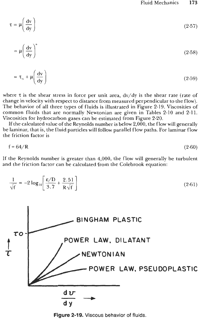
The behavior of all three types of fluids
is
illustrated in Figure 2-19. Viscosities of
common fluids that are normally Newtonian are given in Tables 2-10 and 2-11.
Viscosities for hydrocarbon gases can be estimated from Figure 2-20.
If the calculated value of the Reynolds number is below 2,000, the flow will generally
be laminar, that is, the fluid particles will follow parallel flow paths. For laminar flow
the friction factor is
f
=
64/R
(2-60)
If the Reynolds number is greater than
4,000,
the flow will generally be turbulent
and the friction factor can be calculated from the Colebrook equation:
1
-
=
-2 log,,,[
+
"1
R&
&
(2-61)
BINGHAM PLASTIC
TO
-
POWER LAW, DILATANT
NEWTONIAN
t
It
POWER LAW, PSEUDOPLASTIC
dV
dY
*
-
Figure
2-19.
Viscous behavior
of
fluids.

174
General Engineering and Science
Table 2-10
Dynamic Viscosity of Liquids at Atmospheric Pressure [l]
Temp:
"C
"F
0
20 40 60
80
100
32 68
104
140
176 212
Alcohol,
ethyla
Benzenea
Carbon
tetrachloride'
Gasoline,b
sp.
gr.
0.68
Glycerind
Kerosene$'
sp.
gr.
0.81
Mercq
Oil,
machine,.
sp.
gr.
0.907
"Light"
"Heavy"
Water, freshe
Water, saltd
37.02
19.05
28.12
7.28
252,000
61.8
35.19
7,380
66,100
36.61
39.40
25.06
13.62
20.28
5.98
29,500
38.1
32.46
1.810
9,470
20.92
22.61
17.42
10.51
15.41
4.93
5,931
26.8
30.28
647
2,320
13.61
18.20
12.36
8.187
12.17
4.28
1,695
20.3
28.55
299
812
9.672
9.028
6.871
9.884
666.2 309.1
27.11 25.90
164 102
371 200
7.331 5.827
16.3
Computed
from
data
given
in:
"'Handbook
of
Chemistry and Physics," 52d ed., Chemical Rubber Company,
1971-1972.
b"Smithonian Physical Tables,"
9th
rev.
ed.,
1954.
c"Steam
Tables,"
ASME,
1967.
d"American
Institute
of
Physics Handbook," 3d ed., MeCraw-Hill,
1972.
e"Intemational Critical Tables,"
McCmwHill.
Table 2-1 1
Viscosity
of
Gases at 1 Atrn [l]
Temp:
"C
0
20
60
100
200
400
600
800
1000
"F
32 68 140 212 392 752
I112
1472 I832
~~~~~~~~~~~~
Air'
35.67 39.16 41.79 45.95 53.15
Carbon
dioxide*
29.03 30.91 35.00 38.99 47.77
Carbon
monoxide+
34.60 36.97 41.57 45.96 52.39
Helium*
38.85 40.54 44.23 47.64 55.80
Hydrogen*.t 17.43 18.27 20.95 21.57 25.29
Methane*
21.42 22.70 26.50 27.80 33.49
Nitrogen*.t 34.67 36.51 40.14 43.55 51.47
Oxygent
40.08 42.33 46.66 50.74 60.16
Steamt
18.49 21.89 25.29 33.79
Computed
from
data
given
in:
*"Handbook
of
Chemishy and Pb
ies,"
52d
ed.,
Chemical Rubber Company,
1971-1972.
+-Tables
of
Thermal
Roperties
of%-,"
NBS
Ctrmhr564,
1955.
I''
Steam
Tables,"
ASME,
1967.
~~~
70.42 80.72
62.92 74.96
66.92 79.68
71.27 84.97
32.02 38.17
43.21
65.02 76.47 86.38 95.40
76.60 90.87 104.3 116.7
50.79 67.79 84.79
~ ~~
91.75 100.8
87.56 97.71
91.49 104.2
97.43
43.92 49.20
where
E
is the surface roughness. Equation 2-61 can be solved iteratively. If the Reynolds
number falls between 2,000 and
4,000,
the flow is said
to
be in the critical zone, and
it may be either laminar or turbulent.
Equations 2-60 and 2-61 are illustrated graphically in Figure 2-21. This chart is
called a Moody diagram, and it may be used to find the friction factor, given the
Reynolds number and the surface roughness.
Example 2-1
3
Suppose
1,000
gal/min of light machine oil (see Table 2-10) flow through a 100-ft-
long straight steel pipe with a square cross-section, 2 in. on a side. At the inlet
of
the
