Lopez de Lacalle L.N., Lamikiz A. Machine Tools for High Performance Machining
Подождите немного. Документ загружается.

314 J. A. Sánchez and N. Ortega
tems, i.e., low discharge current and short pulse on-time. Roughness values for the
first cut in tool steel are about Ra 2.80
µm. This value can be improved down to
Ra 0.8
µm after two trim cuts. Surface finish is also highly dependent on part ma-
terial. It is common for machine manufacturers to specify minimum values of
surface roughness for hard metal, where using special modules with values below
Ra 0.10
µm can be achieved.
Different aspects affect precision during WEDM cutting. The wire, subjected by
the machine to tensile stress, from a mechanical viewpoint behaves as a beam on
which deformation is induced by the forces acting: dielectric pressure, electrostatic
force, electrodynamic force and electromagnetic force. Modelling the above system
of forces is a classical topic in WEDM research ([1],
[2] and many others). Under
these forces, the wire suffers flexing and vibration that make it lose its vertical equi-
librium position. As a result, wire geometry is not exactly aligned with machine
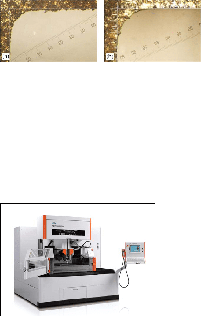
Fig. 9.8 Geometry of the error in corner cutting. a It can be observed that after the first cut, the
amount of material along the corner is not constant. b The situation is clearly improved after trim
cuts
Fig. 9.9 Twin-Wire technology of the Swiss company GF AgieCharmilles
®
. The photograph
shows the FI2050TW machine [20]
9 Wire Electrical Discharge Machines 315
guides (which are the points actually programmed for wire path), and errors are
transferred to the machined part. Deviations in part accuracy include the verticality
of faces, the corner geometry (the so-called “back-wheel effect”) and angular errors
in taper cutting. As already mentioned, accuracy can be greatly improved using trim
cuts where low dielectric pressure and low energy systems are used. For vertical
cuts, verticality can be maintained below 5
µm after two trim cuts in a conventional
WEDM machine. Figure 9.8 shows the geometry of a corner with internal radius
0.20
mm after the first cut (a) and after two trim cuts (b). The geometry is sounder,
the maximum error has been reduced down to 7
µm, and the surface finish has been
clearly improved.
Low-diameter wires are commonly used for machining intricate details and
small internal corner radius. This type of wire is used in the concept of twin-wire
machine developed by the Swiss company GF-AgieCharmilles
®
[20]. Twin-wire
technology incorporates automatic wire change to reduce total machine time and
therefore increase productivity. The first cut is carried out using a low cost wire,
and then trim cuts are performed with wires with diameters as low as 50
µm. This
is a very precise machine, in which excellent roughness, surface finish and dimen-
sional tolerances can be achieved due to the use of thermal stabilisation systems.
Figure 9.9 shows a photograph of the FI2050TW model of this company.
9.3 WEDM Machines
A WEDM machine shares many elements in common with other machine tools.
Structural elements and CNC, for instance, do not differ too much from those of
other manufacturing equipment. However, some systems can only be found in
these machines, and thus they will be separately analysed in the following para-
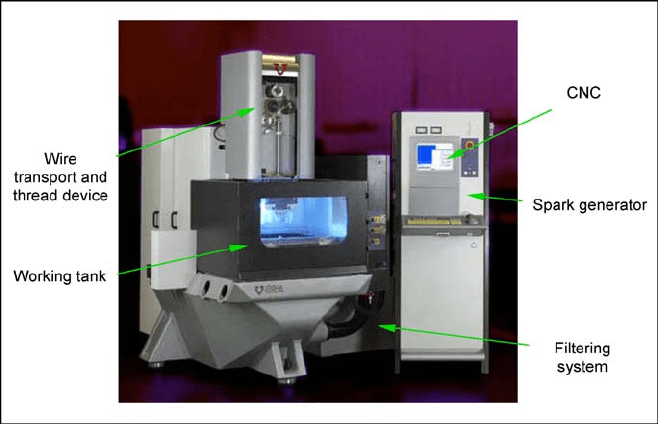
graphs. These elements can be identified in Fig. 9.10.
• Wire transport and wire thread devices.
• A working tank.
• A spark generator.
• A filtering system.
Structural components, mechanical transmission, guiding and measuring de-
vices do not differ too much from those used in other machine tools. Machine
bead is normally built in iron casting, although proposals of using polymer con-
crete can be found both in industry and in literature. In machines where precision
demands are very strict, ceramic components and thermal stabilisation of the
working area can be found.
The guiding system is responsible for the accuracy and straightness of linear
axis movement. Linear guides of hardened steel, held to machine bead, are com-
monly used. This technology increases element wear resistance, although damping
is committed. Movement is transmitted using preloaded linear recirculating ball
bearings mounted on the moving element.
316 J. A. Sánchez and N. Ortega
Fig. 9.10 Main systems of a WEDM machine. The photograph shows an ONA
®
AX300 wire
EDM machine [21]
In most machines, linear axis movement is generated by a transmission engine-
ball screw. The dynamic response of ball screws has increased dramatically in
recent years at the sight of the competence of linear motors. In fact, some manu-
facturers use linear motors for their linear axes, although this is not the most
common option on the market nowadays. Linear motors, due to their extremely
high dynamic response, and lack of backlash, provide a good solution for improv-
ing flushing (the so-called natural flushing) in the sinking the electrical discharge
machining of difficult geometries (for instance, high-depth and low-width slots).
A good example of application of linear motors to the WEDM technology is given
by the AQ300L machine by Sodick
®
[22]. Measuring devices involve precision
glass scales mounted on the axes, and in some cases encoders.
Mechanics of wire electrodischarge machines are, in general, more complex
than those of sinking electrodischarge machines. The machine structure commonly
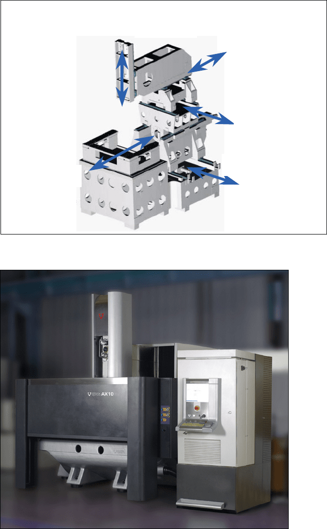
has 5 axes amongst which 4 are interpolated. WEDM machines can be classified
on the basis of the maximum admissible workpiece size. Figure 9.11 shows the
basic mechanical structure of a WEDM machine.
Workpiece height is critical since stability and cutting speed are dependent on it.
Moreover, the WEDM process is the only one on the market capable of precision
cutting of hard parts of high thickness (Fig. 9.12). Currently, there are machines
capable of machining workpieces with the dimensions 2300
×
1300
×
600
mm and
a weight of 10,000
kg. In these large machines, cutting must be carried out in
a submerged mode due to fact that the dielectric has a difficult access to the ma-
chining area. As far as taper cutting is concerned, and depending on the machine,
9 Wire Electrical Discharge Machines 317
Eje Z
Eje X
Eje Y
Eje U
Eje V
V Axis
U Axis
Y Axis
X Axis
Z Axis
Fig. 9.11 Basic diagram of a WEDM machine
Fig. 9.12 ONA
®
AX-10 for the cutting of large thickness parts [21]
318 J. A. Sánchez and N. Ortega
angles as high as ±30º can be cut in a 400
mm thick workpiece, but the angle is
normally limited for higher part thicknesses.
The numerical control of a WEDM machine incorporates some important dif-
ferences with respect to other conventional machine tools, such as machining
centres and turning centres, for instance. In a WEDM machine the servo system
not only closes loops for position and velocity, but it is also in charge of keeping
a constant gap between the wire electrode and the workpiece. Solutions to this
problem involve acquiring and analysing signals related to gap voltage and/or to
delay time. Moreover, “machine intelligence” is of primary importance in WEDM
machines. Manufacturers include in the NC of the machine technological data for
optimum cutting of different materials and thicknesses, strategies for improvement
of accuracy in corner cutting, the intelligent selection of EDM parameters for
situations of degraded erosion (such as stepped parts, large thickness parts, taper
cutting, etc.), and systems for avoidance of wire breakage, amongst others. Some
of these will be addressed in Sect. 9.3.3.
9.3.1 Wire Transport and Wire Thread Devices
As said before, in most cases wire wear is not considered in WEDM since wire
is continuously fed between pulleys. The wire supplying spool can contain from
1.6 to 45
kg with 3,700
m and 105,000
m respectively, and in the case of wire
diameter 0.25
m. With the aim of assuring wire position, different pulley configu-
rations have been designed by manufacturers providing the wire with the pro-
grammed feed rate and axial tension. Prior to and after the machining zone, the
wire is driven through two guides (the upper and lower guide) corresponding to
the nominal position programmed.
The guides are wear resistant accuracy devices; hence, they are made from sap-
phire or diamond. The guide diameter depends on the wire diameter used. There
are, however, several wire thread systems based on wire drawing which allow
using the same guides for a range of wire diameters.
There are two types of wire guides used by manufacturers on their wire EDM
machines. Round or toroidal shaped wire guides are used by a number of EDM
manufacturers, which may provide a slight advantage when machining larger
tapers. A round wire guiding system may help to produce a slightly better finish in
larger taper angles (greater than 15’). A round guide requires some clearance
(∼5
μm) to thread the wire through the guide. However, a number of manufactur-
ers use V-type wire guides due to their reliability for automatic wire threading.
The nozzles drive the upper and lower flushing pressure jet. It becomes appar-
ent that the location of the nozzles, especially in the lower arm, can be affected by
these higher flushing pressures. Hence, a more rigid mechanical structure can
withstand higher flushing pressures better. Nozzle geometry varies also in the
taper cutting to accommodate the wire deformation shape.
9 Wire Electrical Discharge Machines 319
Once the wire has passed through the lower guide, it enters the second part of
the transport system called the evacuation system. The wire passes through the
evacuation tube to the pinch roller after which the wire is cut to store.
Axial force is imposed on the wire to ensure straightness during cutting. Wire
straightness is critical for precision applications. As explained in Sect. 9.2.2, the
forces exerted during the process, due to the discharge and dielectric jet, tend to
deform the wire. As a result accuracy is lost, since the points where discharges
occur do not exactly match the position of the guides (i.e., the position pro-
grammed in the NC path). The value of the axial force imposed by the machine is
limited by the mechanical strength of the wire and its diameter. Thermal load on
the wire produced by continuous discharges also affects its resistance.
Nowadays, apart from these devices, most of the wire EDM machines have
some kind of automatic wire thread (AWT) system which automatically provides
thread or re-thread through the slot or start hole, with nearly 100% reliability.
Automatic wire threading is much simpler and more reliable than manual thread-
ing, primarily when wires with low tensile stress resistance are used. Most AWT
systems heat, draw and guide the wire by high pressure flushing water or air.
AWT systems provide the guides with much longer life and therefore lower cost
per hour and downtime.
9.3.2 Machine Automation
Automating EDM processes is a key aspect in the way to optimise productivity
and work throughput, running machines continuously and unattended. Thus, major
EDM machines manufacturers have developed new devices with the aim of mini-
mising downtimes. In this section, various devices recently established commer-
cially are presented.
The concept of cylindrical wire EDM is based on a rotary axis added to a con-
ventional two-axis wire EDM machine to enable the generation of a cylindrical
form. As conventional 2D machining, the electrically charged wire is controlled
by the X and Y slides to remove the work material and generate the desired cylin-
drical form. The original idea of using wire EDM to machine cylindrical parts was
first reported by Prof. Masuzawa’s research group at the University of Tokyo in
1985 [9], and this configuration has eventually been industrialised. The Mitshubi-
shi Electric
®
BA8 submerged WEDM machine, equipped with rotating spindle for
EDM-turning and EDM-grinding applications, and the CNC ONA-W64 (by ONA-
Electroerosion
®
S.A.) capable of controlling 6 axes are examples of this applica-
tion. Of course, special machines can be customised. The configuration of 6 con-
trolled axes was first aimed at the manufacture of small-diameter pins and shafts
to be used as tools for 3D micro-EDM applications [13]. Nowadays, new fields of
application are emerging, such as tool sharpening, diesel engine injector plungers,
gear wheels with integrated shafts for easy gear assembly, conductive bonded grind-
ing wheel dressing, parts for medical industries and aerospace parts industries.
320 J. A. Sánchez and N. Ortega
No doubt, one of the critical concerns in WEDM application is wire breakage.
The demands for a very high cutting speed and overnight cutting without atten-
dance require wire breakage prevention since this would result in unacceptable
increases of machining times, a decrease in machining accuracy, and the deteriora-
tion of the machined surface. A great amount of research effort into wire breakage
prevention has been carried out which concluded wire breakage could be identi-
fied by symptoms such as high gap voltage, a sudden rise in the total sparking
frequency, and an excessive instantaneous energy rate.
Control strategies to prevent wire breakage are therefore based on pulse dis-
crimination according to the characteristics of voltage waveform during machin-
ing for the purpose of improving machining stability and efficiency. To do so,
the control system analyses each discharge and evaluates ignition delay and
frequency of the pulse current as an indication of arcing. Once instability is de-
tected, the system corrects gap distance recovering a stable state. Modern digital
EDM generators include any pulse monitoring system which means a wire break-
age prevention system in the case of WEDM. Adaptive control systems provide
effective control of the cuttings process, automatically modifying the program-
med parameters of the power supply, ensuring optimum machine performance at
each stage.
There are a number of other topics dealing with productivity and accuracy
which can obtain enormous benefit from adaptive control systems. For instance,
complex pieces like staggered components, parts with wide taper cut angles etc.,
can be EDM’ed resulting in improvements of as much as 30% in the cutting speed
when compared with conventional control systems. Industrial examples of such
systems are the AI (artificial intelligence) workpiece thickness adaptive control
developed by Fanuc
®
, the Expert Erosion System by ONA Electroerosión
®
, the
AutoMagic by Mitsubishi Electric
®
, and the Pilot Expert 3 by Agie-Charmillies
®
.
Advanced research work in this field includes the use of knowledge-based control
systems [16], explicit mathematical models [4], neural networks [8], and fuzzy
logic controllers [15].
Intelligence is also introduced in the setting of EDM parameters after restarting
a terminated process. In machines equipped with AWT systems (see Sect. 9.3.2) if
the same parameter setting as that before wire breakage is used, the process tends
CNC
BRAKE SERVO
MOTOR
FEED SERVO
MOTOR
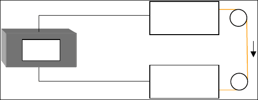
Fig. 9.13 Diagram of Twin Servo Wire Tension Control (patent pending) developed by Fanuc
®
Co.
9 Wire Electrical Discharge Machines 321
to experience breakage again after restart. Thus an “intelligent” system is usually
called up to change the parameter setting after each wire breakage. It is actually
off-line knowledge about wire breakage.
As already explained, strict control of the axial force imposed by the machine
is critical to ensure wire straightness. A good example of machine intelligence
applied to the process is the Twin-Servo Wire Tension Control system developed
by Fanuc, which uses servo motors to control wire tension and wire feeding. By
applying Fanuc's digital servo technology to the wire feeding system, variation in
tension is reduced to less than one fourth of previous systems, resulting in stable
high speed and high precision machining. This function, represented in Fig. 9.13,
is available in the high speed and precision Wire-Cut EDM Fanuc Robocut α-iD
series [19].
9.3.3 Workpiece Fixturing Systems
Palletising is very closely related to automation. The link between mechanical
interfaces – such as those between a workpiece and a machine tool – that have
interchangeability, modularity and flexibility, is a critical first step toward elimi-
nating the downtime associated with workholding. This became even more impor-
tant in the case of EDM machines due to the long machining times associated to
the process. Many workpiece holders’ manufacturers have developed new palletis-
ing systems compatible among machines with very different configurations. For
instance, this is the case of WEDM machines. In these machines, the work table is
formed by two stainless steel guides with plenty of threaded holes and whose work
surface is in a specific position related to the XY-plane and which is arranged in
the direction of movement of the tool. It is necessary to transport the chuck-
mounted work piece from one processing location to the next without changing
workpiece alignment, e.g., in an orthogonal system.
Standardisation provides a stable reference system. However, it is modularity
which gives a method of dealing with various applications. Modularity is the key
to processing different sizes and shapes of workpiece blanks.
Erowa
®
, Hirschmann
®
and System 3R
®
are probably the best known manufac-
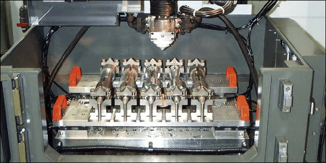
turers for workpiece palletising systems (Fig. 9.14). There are countless possible
combinations in the product range adapted to any single application set up by refer-
ence elements, mounting heads, chuck adapters, rulers, adapter elements, support-
ing elements, and presetting/inspection devices. These devices allow the user to set
up the machine quickly with high-quality repeatability specifications. A repetitive
accuracy (consistency) for these systems is quoted in all the cases at 0.002
mm.
Growing demands on the manufacturing industry must be met with increased
flexibility, increased quality and increased productivity. So, workpiece fixturing
systems’ manufacturers also provide pallet handling robots as effective with one-
off manufacturing as with mass production. Examples of robots such as the
WorkMaster by System 3R
®
, the Robot Multi ERM by Erowa
®
, and the Erobot
322 J. A. Sánchez and N. Ortega
4018 Workpiece Changer by Hirschmann
®
can be cited as examples that provide
a significant impact on productivity, profitability and competitiveness.
9.3.4 Filtering Systems
The filtering system is responsible for supplying the dielectric with suitable con-
ditions into the erosion area. In most applications tap water conductivity is re-
duced to 106
Ω⋅cm, although some new materials such as hard metal must be
machined with less conductivity prevent corrosion. Once tap water is electrically
conditioned, it is used as a dielectric to cool and evacuate the debris from the
machining which increases dielectric conductivity. No matter which filtering
system is used, electrical conductivity is reduced employing special resins. If
accuracy demands must be met, cooling capacity must be ensured using an exter-
nal cooling system.
There are two main types of filtering systems: paper cartridge filters and min-
eral filters. Paper cartridge filters are replaceable or consumable which can be
used for 200–300 working hours depending on the EDM process, water volume,
etc. The filtering media consists of pleated impregnated cellulose base material
which is cured and retained within the inner and outer screens by means of hot
melt glue. The construction feature prevents excessive movement of the cellulose
fibre in humid conditions and maintains an even pleat-spacing thus ensuring the
most effective usage of the available media surface area. Nowadays, filters assure
a consistent EDM fluid quality, and uniform process condition to avoid blockage
of rinsing nozzles, increase resin consumption, sediment in the cooling and supply
system, and to increase corrosion deposits. Flow and particle size are kept constant
(particles over 1–3
μm are kept out) throughout the entire machining process with
Fig. 9.14 Example of duplication of frame systems by System 3R
®
[23]
9 Wire Electrical Discharge Machines 323
repeatable quality results. In some cases, WEDM machine manufacturers also
manufacture filtering systems.
Mineral filter systems for wire EDMs do not require filter media replacement.
It is a stand-alone unit which takes dirty water from the machine filtering it to
a 3-micron cleanliness level to supply clean water for machining. When the filter
vessel reaches its cleaning capacity, as detected by a pressure switch, a backwash-
ing cycle starts and clean filtered water is supplied to the machine dielectric tank.
With this feature the machine always has a supply of clean water.
9.4 Wires for WEDM
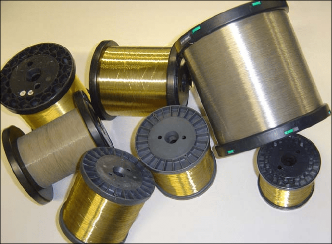
The correct choice of the wire for WEDM (Fig. 9.15) is a critical point in optimis-
ing the process. For each type of wire the user must be aware of the physical and
chemical properties which influence the cutting process, together with the eco-
nomic aspects that surrounding it. The result of a proper choice is a stable cut, eco-
nomical and at maximum speed. It is obvious that the cheapest wire is not always
the optimum solution for a certain application.
The first wires ever used were made of copper. Previous experience in SEDM ma-
chines using this material, and the availability of the technology for wire production
in diameters 0.2
mm and 0.25
mm made copper the first option. However, the poor
Fig. 9.15 Wires for WEDM
