Linden D., Reddy T.B. (eds.) Handbook of batteries
Подождите немного. Документ загружается.

29.12 CHAPTER TWENTY-NINE
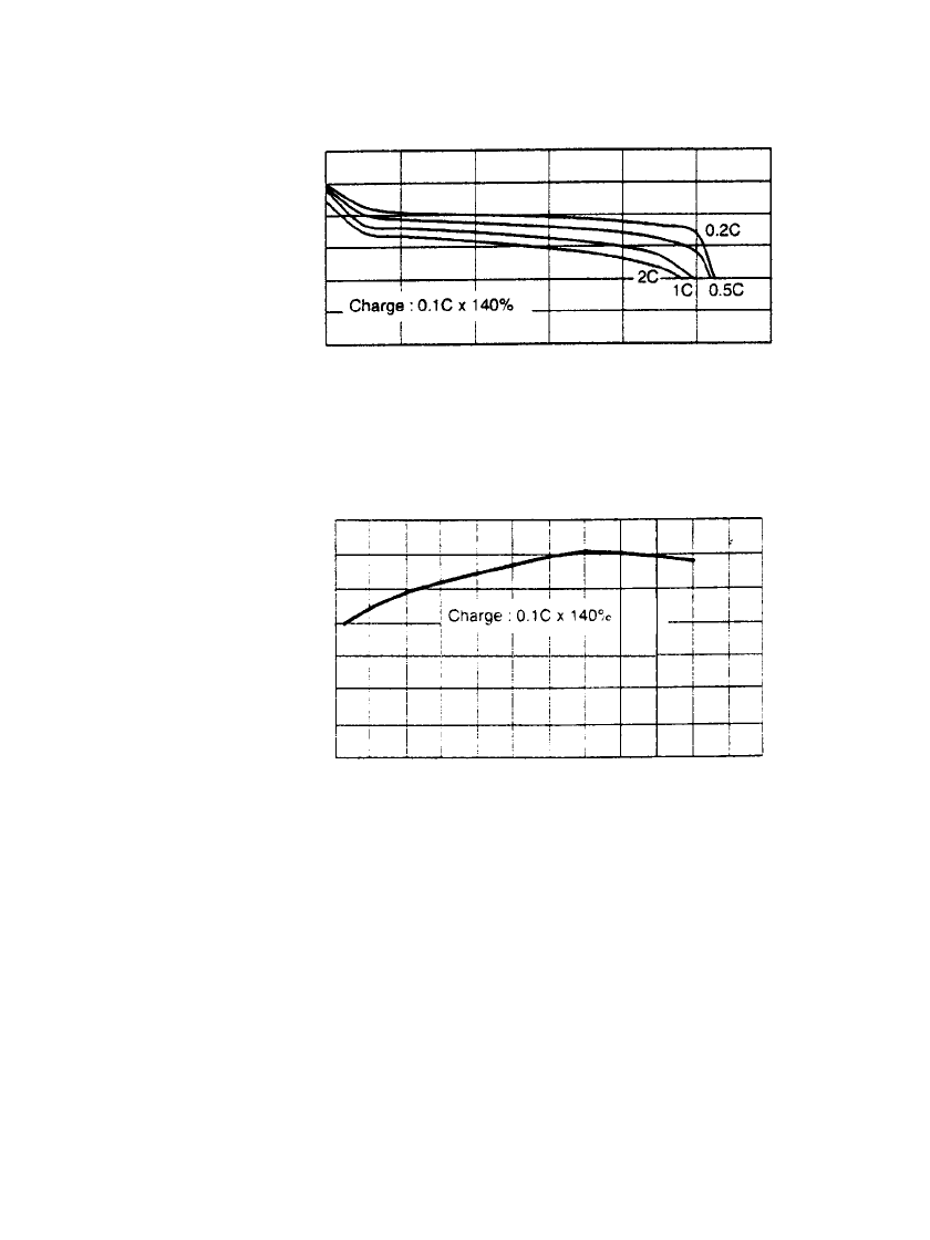
9-Volt Battery. Typical discharge curves for the 9-volt sealed nickel-metal hydride battery
at room and other temperatures are shown in Figs. 29.6a and 29.6b.
11
10
9
8
7
6
5
Voltage (V)
020
40 60
80
100
120
Capacity Discharged (%)
(a)
-20 -10
0
10 20
30 40
Discharge Temperature ( C)
(b)
o
140
120
100
80
60
40
20
0
% of Nominal Capacity
FIGURE 29.6 Discharge characteristics of 9-volt sealed nickel-
metal hydride battery (a) Discharge at 20⬚C. (b) Discharge at 0.2 C
rate to 7 volts. (Courtesy of GP Batteries, Inc.)
29.4.3 Effect of Discharge Rate and Temperature on Capacity
The ampere-hour capacity of the battery also is dependent on the discharge current and
temperature, as can be observed in Fig. 29.3 through Fig. 29.6. It should also be noted that
the delivered capacity is dependent on the cutoff or end voltage. The capacity can be in-
creased by continuing the discharge to lower end voltages, particularly at the higher current
drains and lower temperatures, where the voltage drops off more rapidly than at the lighter
drains. However, the battery should not be discharged to too low a cutoff voltage as the cells
may be damaged (see Sec. 29.4.6). The cutoff or end voltage for the nickel-metal hydride
battery is typically 1.0 V per cell.
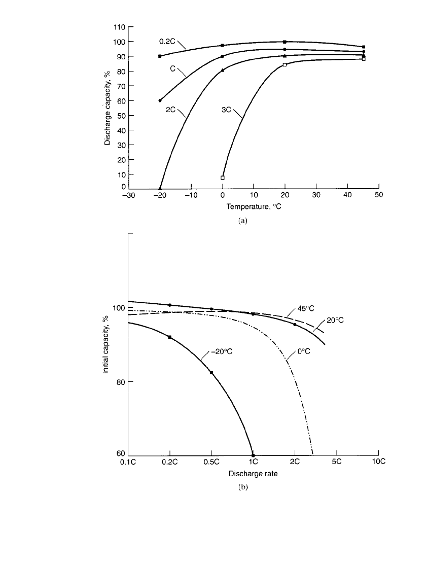
The relationship of the ampere-hour capacity (expressed as a percentage of the capacity
at 20
⬚C on a discharge at the 0.2C rate) of the sealed nickel-metal hydride battery and the
discharge temperature and current (expressed in C rate) is summarized in Fig. 29.7.
PORTABLE SEALED NICKEL-METAL HYDRIDE BATTERIES 29.13
FIGURE 29.7 (a) Discharge capacity vs. ambient temperature for sealed cylindrical
nickel-metal hydride batteries at various discharge rates; end voltage 1.0 V / cell. (b)
Discharge capacity (% of 0.2C rate) vs. discharge rate (C-rate) for sealed cylindrical
nickel-metal hydride batteries at various temperatures: end voltage 1.0 V / cell.
29.14 CHAPTER TWENTY-NINE
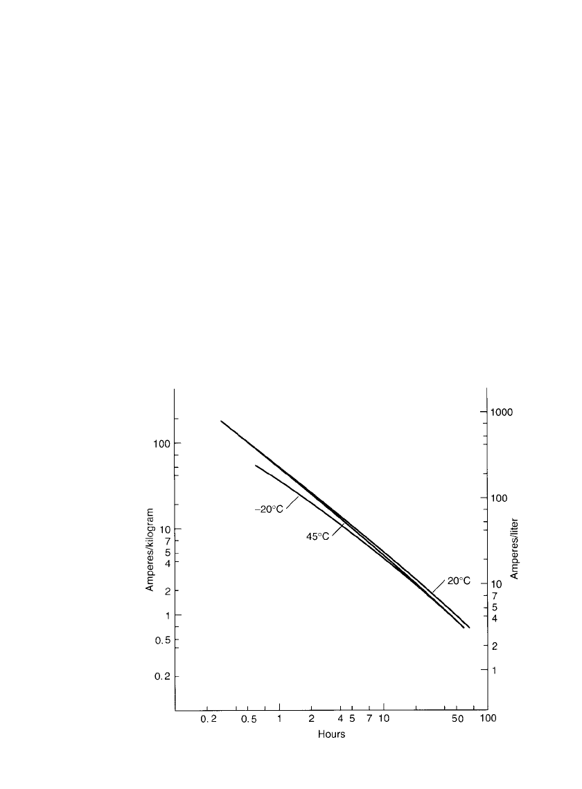
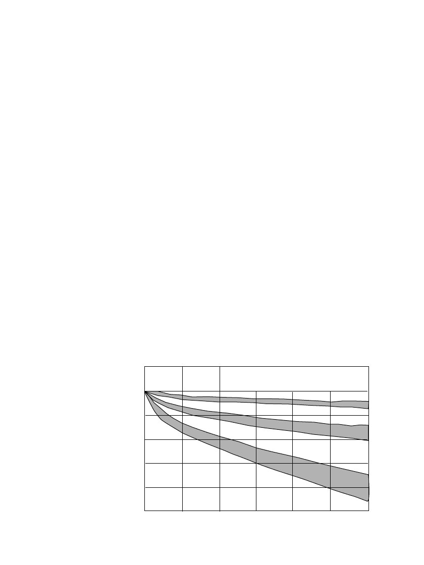
FIGURE 29.8 Service life of sealed standard cylindrical nickel-metal hydride
batteries at various discharge rates and temperatures. Based on an energy density
under rated conditions at 20⬚C of 60 Ah / kg and 200 Ah / L: end voltage 1.0
V / cell.
Typically, for the nickel-metal hydride battery the best performance is obtained between
0 and 40
⬚C. The performance characteristics of the battery on discharge are affected mod-
erately at higher temperatures, but decrease more significantly at the lower discharge tem-
peratures, mainly due to the increase in internal resistance. Similarly, the effects of a change
in temperature are more pronounced at the higher discharge rates. The capacity of the battery
decreases more noticeably as the current increases beyond the 3 to 4C rate, particularly at
the lower temperatures.
A drop in the capacity can be observed at the lower discharge rates and higher temper-
atures. This loss in capacity is due to the effect of self-discharge, which can become evident
under these discharge conditions.
29.4.4 Service Life (Hours of Service)
Figure 29.7 can be used to approximate the capacity and the service life of standard cylin-
drical nickel-metal hydride batteries at various discharge rates and temperatures if the rated
capacity (at 20
⬚C and the 0.2C discharge rate) is known. The percentage of the rated capacity
delivered under other conditions can be determined directly from this figure. The approxi-
mation is valid if the cells are of a similar construction and behave similarly to the standard
cell on which the data are based. The specific data for a given cell type obtained from the
manufacturer should be used to estimate the performance more precisely.
Another form for presenting these data is shown in Fig. 29.8. The service life, in hours,
of a cylindrical nickel-metal hydride battery is plotted against the discharge current, nor-
malized to unit weight (Ah /kg) and size (Ah/L). These data are based on a rated capacity
PORTABLE SEALED NICKEL-METAL HYDRIDE BATTERIES 29.15
at the 0.2C rate of 60 Ah /kg and 200 Ah/ L, reflecting the performance of a standard type
battery. As discussed in Sec. 3.2.6, this figure provides a convenient nomograph to determine
the approximate performance, in service hours, of a battery or to estimate the size of a
battery that will deliver the desired performance under specified discharge conditions—again
with the caveat that the battery has similar construction and characteristics to the standard
battery on which the data are based and an energy density close to the one specified.
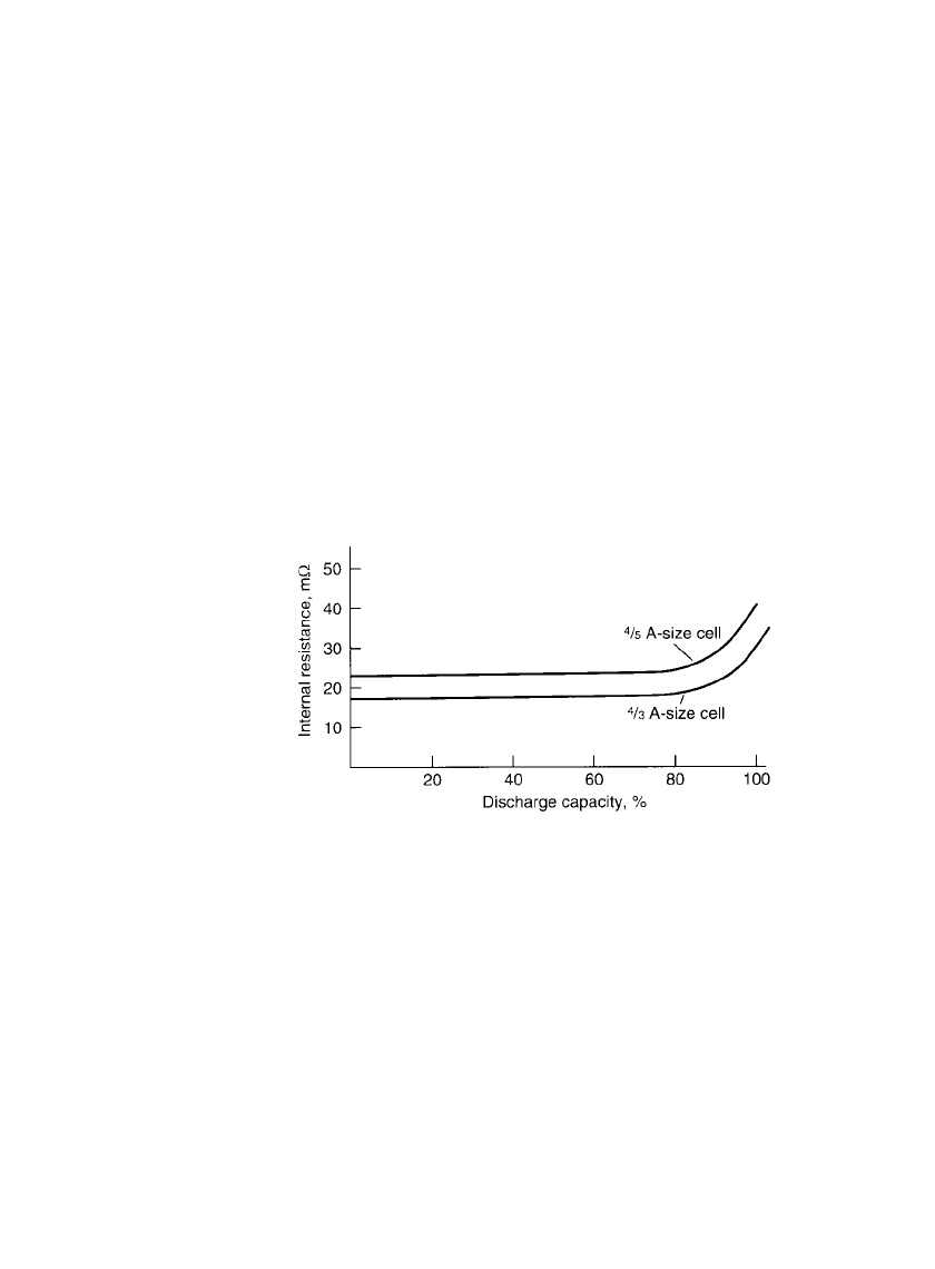
29.4.5 Internal Resistance
The nickel-metal hydride battery has a low internal resistance because of the use of thin
plates with large surface areas and low resistance and an electrolyte having a high conduc-
tivity. Figure 29.9 shows the change in internal resistance with the depth of discharge. The
resistance remains relatively constant during most of the discharge. Toward the end of the
discharge, the resistance increases due to conversion of the active materials. The internal
resistance also increases as the temperature drops because the resistance of the electrolyte
and other components is higher at the lower temperatures. The resistance of the nickel-metal
hydride battery increases with use and cycling. This is illustrated in Fig. 29.24a which shows
the drop in midpoint voltage as the battery is cycled.
FIGURE 29.9 Internal resistance vs. discharge capacity of
sealed cylindrical nickel-metal hydride cells.
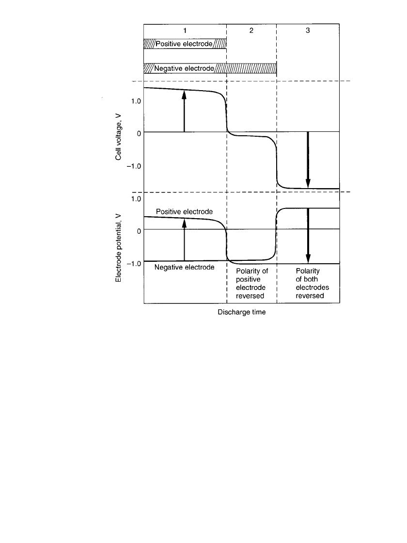
29.4.6 Polarity Reversal during Overdischarge
When a multicell series-connected battery is discharged, the lowest-capacity battery will
reach the point of full discharge before the others. If the discharge is continued, this lower-
capacity cell can be driven into an overdischarged condition through 0 V and its polarity
(voltage) reversed. This is illustrated in Fig. 29.10.
Phase 1 of the figure is the normal phase of the discharge with active material remaining
on both the positive and the negative electrodes.
During phase 2 the active material on the positive electrode has been discharged and
generation of hydrogen gas starts. Some of this gas may be absorbed by the hydrogen storage
metal alloy in the negative electrode and the remainder builds up in the cell. Active material,
however, still remains on the negative electrode and the discharge continues. The cell voltage
is dependent on the discharge current, but remains within
⫺0.2 to about ⫺0.4 V.
In phase 3 the active materials on both electrodes have been depleted and oxygen is
produced at the negative electrode. Prolonged overdischarge leads to gassing, higher internal
cell pressure, opening of the safety vent, and deterioration of the cell.
29.16 CHAPTER TWENTY-NINE
FIGURE 29.10 Polarity reversal during discharge of sealed cylindrical
nickel-metal hydride cells.
The larger the number of cells in series in a multicell battery, the greater the possibility
that this polarity reversal will occur. To minimize the effect, whenever three or more cells
are connected in series, the cells selected should have capacities within the range of
5%.
The process of selecting cells of similar capacity is called ‘‘matching.’’ Further, a cutoff
voltage of 1.0 V per cell or higher should be used for discharge rates up to the 1C rate to
prevent the possibility for any cell to go into reversal. Higher cutoff voltages should be used
for batteries containing more than 10 cells in series and for discharge rates exceeding 1C.
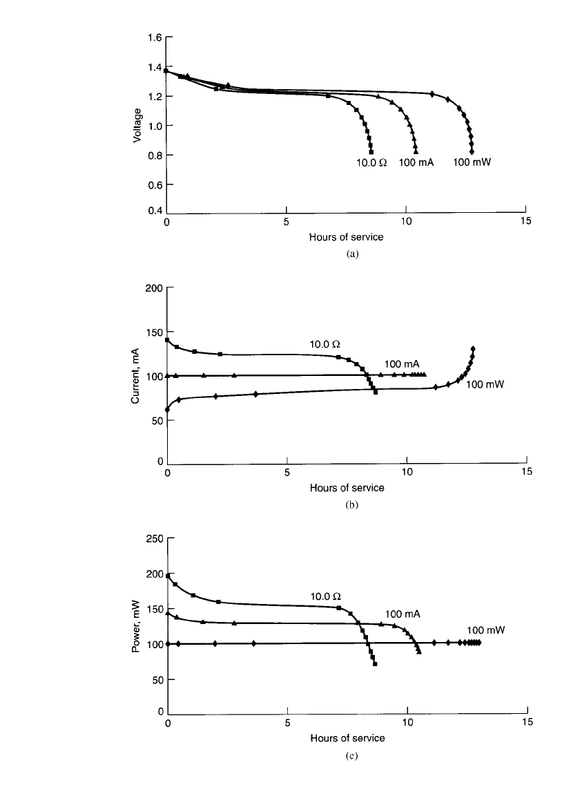
29.4.7 Type of Discharge
As discussed in Secs. 3.2.3 and 3.2.4, a battery may be discharged under different modes
(such as constant resistance, constant current, or constant power), depending on the char-
acteristics of the equipment load. The type of discharge mode selected has a significant
impact on the service life delivered by a battery in a specified application. The discharge
profiles of a nickel-metal hydride battery under the three different modes are plotted in Fig.
29.11. Figure 29.11(a) shows the voltage profile, Fig. 29.11(b) the current profile, and Fig.
29.11(c) the power profile during discharge of the battery. As an example, the data are based
on the discharge of a 1000-mAh battery such that, at the end of the discharge (1.0 V per
PORTABLE SEALED NICKEL-METAL HYDRIDE BATTERIES 29.17
FIGURE 29.11 Discharge of sealed cylindrical nickel-metal hydride batteries—constant
power vs. constant current vs. constant resistance: (a) Voltage profile. (b) Current profile.
(c) Power profile. —constant resistance: —constant power; 䉱—constant current.
Based on a battery rated at 1000 mAh.
29.18 CHAPTER TWENTY-NINE
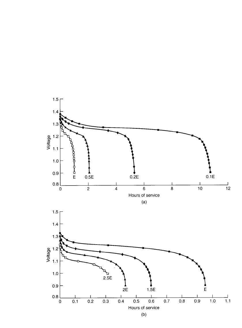
FIGURE 29.12 Constant-power discharge curves for sealed cylindrical nickel-metal hydride bat-
teries at 20⬚C. (a) 0.1E to 1E discharge rate. (b)1E to 2.5E discharge rate.
cell), the power output is the same for all modes of discharge. In this example the power
output at the 1.0-V cutoff is 100 mW. To discharge at 100 mW at 1.0 V, the constant-current
discharge is 100 mA (C /10 rate) and the constant-resistance discharge is 10
⍀. As shown,
the longest service life is obtained under the constant-power mode as the average current is
the lowest under this mode of discharge.
29.4.8 Constant-Power Discharge Characteristics
The discharge characteristics of the nickel-metal hydride battery under the constant-power
mode, at several different power levels, are shown in Fig. 29.12. These are similar to the
data presented in Fig. 29.3a for constant-current discharges, except that the performance is
PORTABLE SEALED NICKEL-METAL HYDRIDE BATTERIES 29.19
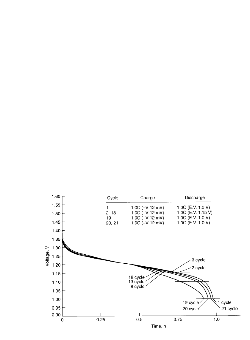
FIGURE 29.13 Voltage depression during cycling of sealed cylindrical nickel-metal hydride bat-
tery, 20⬚C. (Courtesy of Duracell, Inc.)
presented in hours of service instead of percent ampere-hour capacity. The power levels are
shown on the basis of E-rate. The E-rate is calculated in a manner similar to calculating the
C-rate but based on the rated watthour capacity rather than ampere-hour capacity. For ex-
ample, for the E/2 power level, the power for a battery rated at 1200 mWh (rated at 1000
mAh at the C /5 rate at 1.2 V) is 600 mW.
29.4.9 Voltage Depression (Memory Effect)
A reversible drop in voltage and loss of capacity may occur when a sealed nickel-metal
hydride battery is partially discharged and recharged repetitively without the benefit of a full
discharge. This is illustrated in Fig. 29.13. After an initial full discharge (cycle 1) and charge,
the battery is partially discharged (in this example to 1.15 V) and recharged for a number
of cycles. During this cycling the discharge voltage and the capacity drop gradually (cycles
2 to 18). On a subsequent full discharge (cycle 19) the discharge voltage is depressed com-
pared to the original full discharge (cycle 1). The discharge profile may show two steps, and
the cell does not deliver the full capacity to the original cutoff voltage. This phenomenon is
known as voltage depression. At times it is referred to as ‘‘memory effect,’’ as the battery
appears to ‘‘remember’’ the lower capacity. The battery can be restored to full capacity with
a few full discharge-charge cycles, as illustrated in Fig. 29.13 (cycles 20 and 21).
The voltage drop occurs because only a portion of the active materials is discharged and
recharged during shallow or partial discharging. The active materials that have not been
cycled change in physical characteristics and increase in resistance. The active materials are
restored to their original state by the subsequent full discharge-charge cycling.
The extent of voltage depression and capacity loss depends on the depth of discharge and
can be avoided or minimized by discharging the battery to an appropriate end voltage. The
effect is most apparent when the discharge is terminated at the higher end voltages, such as
29.20 CHAPTER TWENTY-NINE
Model: HR-4/5AU
Charge:0.1Cx16h
Discharge:1C, E.V.=1.0V
25 C
40 C
120
100
80
60
40
20
0
0 10 20 30 40 50 60
Storage period (days)
Residual capacity (%)
o
o
0 C
o
FIGURE 29.14 Charge retention characteristics of sealed cylindrical nickel-
metal hydride batteries at various temperatures (Courtesy of Sanyo Electrical
Co. Ltd.)
1.2 V per cell. A smaller loss occurs if the discharge is cut off between 1.15 and 1.10 V
per cell. Discharging to an end voltage below 1.1 V per cell should not result in a significant
voltage depression or capacity loss on the subsequent discharges. Discharging to too low an
end voltage, however, should be avoided, as discussed in Sec. 29.4.6.
The effect is also dependent on the discharge rate. To a given end voltage, the depth of
discharge will be less on discharges at the higher rates. This will increase the capacity loss
as less of the active material is cycled.
While the memory effect may result in reduced battery performance, the actual voltage
depression and capacity loss are only a small fraction of the battery’s capacity. Most users
may never experience low performance due to this behavior of the sealed nickel-metal hy-
dride cell. Often memory effect is used incorrectly to explain a low battery capacity that
should be attributed to other problems, such as inadequate charging, overcharge, or exposure
to high temperatures.
29.4.10 Self-Discharge and Charge Retention
The state of charge and capacity of the nickel-metal hydride battery decreases during storage
due to self-discharge. This is caused by the reaction of the residual hydrogen in the cell (the
atmosphere inside the cell is hydrogen) with the positive electrode as well as the slow (but
reversible during subsequent charging) decomposition of both electrodes.
The rate of self-discharge is dependent on the storage temperature and time: the higher
the temperature, the greater the rate of self-discharge. This is illustrated in Fig. 29.14, which
shows the charge retention for sealed cylindrical nickel-metal hydride batteries following
storage at different temperatures for varying periods of time. The comparison is for a battery
discharged at the rated discharge load (approximately the 0.2C rate) at 20
⬚C. It is to be noted
also that the charge or capacity retention also is dependent on cell size, cell design, discharge
and charge conditions and other such factors. The more stringent the discharge condition
such as a higher rate or lower temperature, for example, the lower the capacity retention.
The charge retention characteristics for the other types of sealed nickel-metal hydride bat-
teries are similar to those shown for the cylindrical batteries.
PORTABLE SEALED NICKEL-METAL HYDRIDE BATTERIES 29.21
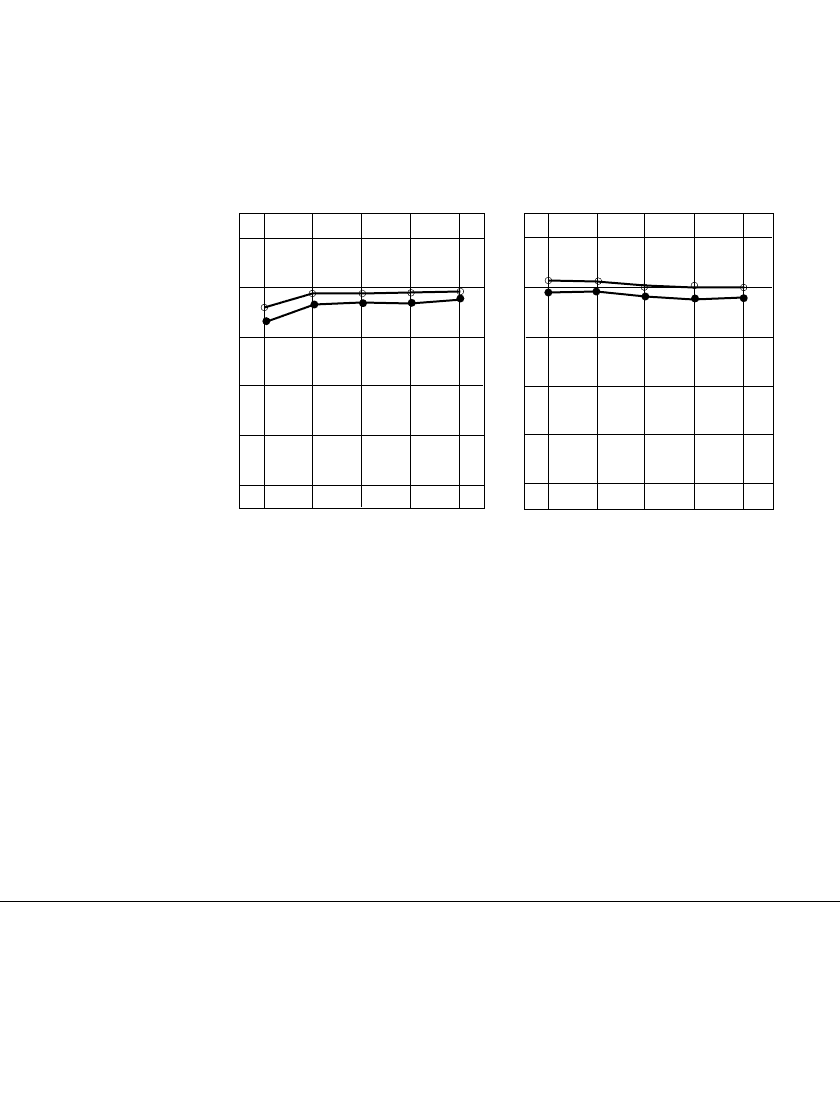
In general long-term storage of the nickel-metal hydride cell, in either a charged or a
discharged condition, has no permanent effect on its capacity. The capacity losses due to
self-discharge are reversible and batteries can recover to full capacity by recharging. This is
shown in Fig. 29.15. Full capacity can be restored within two to three charge-discharge
cycles.
110
100
90
80
70
60
Battery capacity (%)
110
100
90
80
70
60
1 2 3 4 5
1 2 3 4 5
Number of cycles after storage
(a)
Number of cycles after storage
(b)
FIGURE 29.15 Capacity recovery after storage. (a) Storage for one month in charged
state. (b) Storage for one month in discharged state. Charge 0.1C
⫻ 16 h; discharge 1C;
end voltage 1.0 V; 20⬚C. —storage at 25⬚C ●—storage at 40⬚C. (Courtesy of Sanyo
Electric Co, Ltd.)
Long-term storage at high temperatures, similar to operation at elevated temperatures,
may deteriorate seals and separators and could cause permanent damage, such as loss of
capacity, cycle life, and overall battery lifetime. The recommended temperature range for
long-term storage of nickel-metal hydride cells is 20 to 30
⬚C.
29.5 CHARGING SEALED NICKEL-METAL HYDRIDE BATTERIES
29.5.1 General Principles
Recharging is the process of replacing energy that has been discharged from the battery. The
subsequent performance of the battery, as well as its overall life, are dependent on effective
charging. The main criteria for effective charging are to:
•
Recharge the battery to its full capacity
•
Limit the extent of overcharge
•
Avoid high temperatures and excessive temperature fluctuations