Linden D., Reddy T.B. (eds.) Handbook of batteries
Подождите немного. Документ загружается.

RECHARGEABLE LITHIUM BATTERIES (AMBIENT TEMPERATURE) 34.41
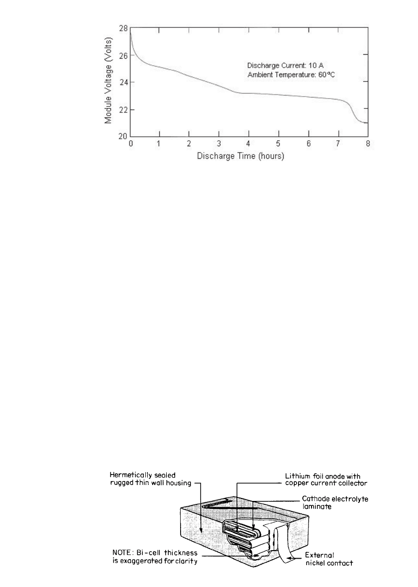
FIGURE 34.23 Typical discharge curve of the Argo-Tech’s battery NPS-4V80.
(Reprinted by permission of 3M Company, St. Paul, Minnesota.)
FIGURE 34.24 Schematic of a SPE battery design configuration. (From Va-
lence Technology, Inc.)
Polymer Electrolyte Battery Using V
6
O
13
. The design of another configuration of an SPE
cell which was being developed for portable applications and for scaling up to larger batteries
is illustrated in Fig. 34.24. A folded ‘‘bicell,’’ which is formed by folding the cathode lam-
inate and inserting the lithium foil anode, is the basic assembly unit. The bicells are stacked,
the terminal leads are attached, and the unit is hermetically sealed into the final package.
The size and number of stacks used in each cell assembly depend on the desired capacity
and cell and battery dimensions.
43
The heart of the process was the fabrication of the polymer laminate for the cathode. The
cathode formulation, including polymer precursor, vanadium oxide, and carbon, was mixed
and coated onto the carbon current collector. A second layer, the electrolyte, was coated on
the cathode to provide the ionic conductivity and separate the cathode from the lithium
anode. The coated laminate was then passed through an electron beam generator to cross-
link the polymer precursors and produce the solid polymer material.
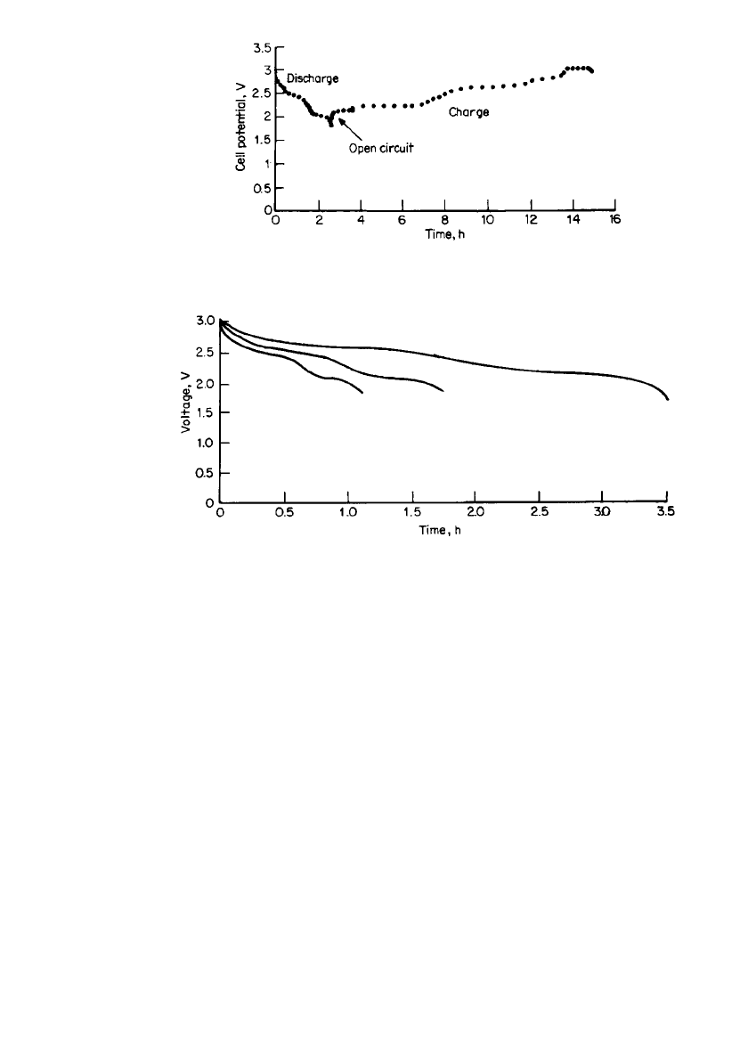
Figure 34.25 shows the discharge-charge curve for this lithium polymer battery, using a
lithium foil anode and a vanadium oxide cathode (V
6
O
13
). The capacity of the battery is
about 50 mAh. The discharge curves at different rates at 20
⬚C are shown in Fig. 34.26. The
sloping discharge profile is characteristic of the intercalation cathode. The voltage plateaus
relate to the intercalation of the lithium ions into the vanadium oxide. The midpoint voltage
decreases with increasing current, but there is relatively little change in Ampere-hour capacity
if the cell is discharged to 1.8 V at rates slower than the 1-h rate. The self-discharge rate of
these cells was very low, on the order of 0.5% per month at 20
⬚C. The battery was expected
to deliver about 200 cycles, with the capacity dropping slightly with cycling until near the
end of life. During cycling, the impedance of the cell increases gradually, accounting for
this loss of capacity. Work on this system has been discontinued in favor of lithium-ion
technology using PVDF-based electrolytes (see Table 34.16).
34.42 CHAPTER THIRTY-FOUR
FIGURE 34.25 Laboratory prototype SPE cell (50-mAh size).
Typical discharge/ charge curve. (From Valence Technology, Inc.)
FIGURE 34.26 Laboratory prototype SPE cell, typical discharge curves at 20⬚C.
(From Valence Technology, Inc.)
34.4.4 Lithium Batteries Using Sulfur-based Polymeric Positive Electrode
Materials
Polymeric sulfur-based positive electrodes are under development for use in rechargeable
batteries with lithium metal negatives.
55,56
Both liquid dioxolane-based and proprietary pol-
ymer electrolytes have been employed with this system.
55
Examples of the positive electrode
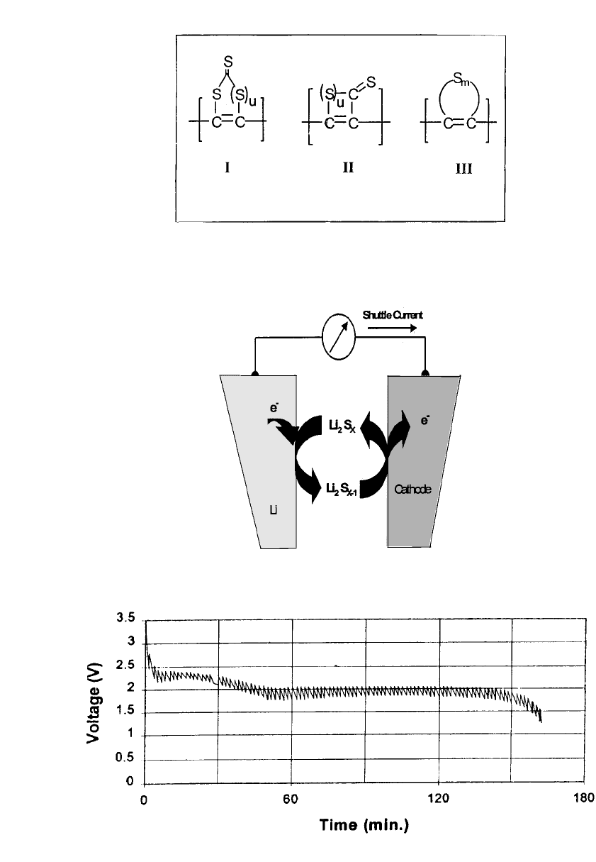
polymers used in this system are shown in Fig. 34.27. These positive electrode materials are
claimed to have specific capacities of 700 to 1200 mAh /g. Initial work was carried out with
AA-size batteries using liquid electrolytes which operated at 2.1 V, provided 1 Ah capacity,
a specific energy of 215 Wh/ kg and an energy density of 260 Wh/ L. This system is claimed
to provide an intrinsic overcharge and over-discharge mechanism involving soluble sulfur
species which shuttle between the electrodes under these conditions. See Fig. 34.28. The
AA-size battery demonstrated its ability to operate on the standardized GSM cell-phone test
as shown in Fig. 34.29 Approximately 200 cycles were obtained under C/3 charge-discharge
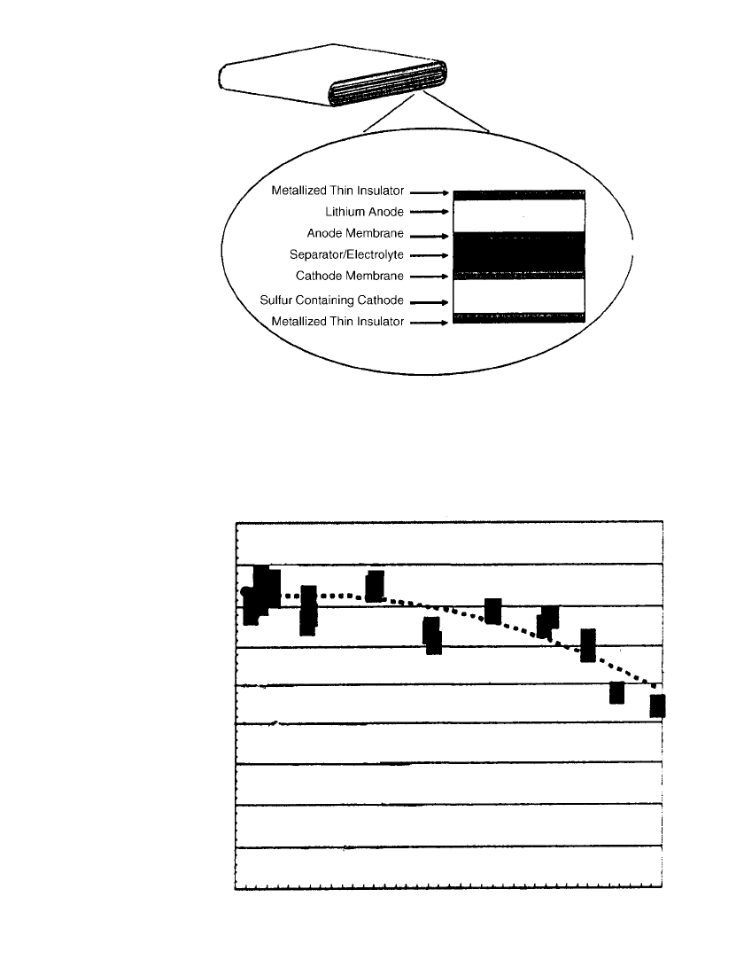
cycling conditions with the AA-size battery. The cylindrical design has been superceded by
a tin-foil laminate structure, which has evolved from 66 micron to 47 micron thickness for
use in flattened wound cell designs. See Fig. 34.30. A 1 Ah unit is projected to have an
electrode surface area of over 1000 cm
2
, allowing operation at low current density. Prismatic
designs (34
⫻ 48 ⫻ 3.5 mm) were stated to give 950 mAh at 2.1 V, providing 310 Wh /kg
and 350 Wh /L. Self-discharge is high, at 10 to 15% per month, probably due to the presence
of soluble sulfur species. This design concept provides high power capability for this system,
as shown in the Ragone plot of Fig. 34.31, which demonstrates that this system is capable
of discharge rates of up to 8C, delivering 800 W/kg at 100 Wh/ kg, which makes it poten-
tially useful in hybrid electric vehicle applications. This technology continues under devel-
opment by several companies.
RECHARGEABLE LITHIUM BATTERIES (AMBIENT TEMPERATURE) 34.43
FIGURE 34.27 Sulfur-based electrode materials consist of congurated
carbon backbones connected to contiguous sulfur rings or chains. Cath-
ode discharge process is a redox reaction in which the sulfur rings open,
providing 700 to 1200 mAh /g. The sulfur rings reform on recharge.
(From Ref. 55.)
FIGURE 34.28 Redox shuttle protection mecha-
nism provided by sulfur-based polymeric materials.
(From Ref. 56.)
FIGURE 34.29 GSM cell-phone test of AA lithium/ sulfur-based cathode AA-size battery. Test consists of
1.5 A pulse for 0.6 millisec followed by 0.1 A for 4.4 millisec. (From Ref. 55.)
34.44 CHAPTER THIRTY-FOUR
FIGURE 34.30 Schematic illustration of thin, flat rechargeable lithium
battery with sulfur-based polymer cathode material. (From Ref. 56.)
0 100 200 300 400 500 600 700 800
Specific Power (W/kg)
0
20
40
60
80
100
120
140
160
180
Specific Energy (Wh/kg)
C2
C
2C
3C
4C
5C
6C
7C
8C
FIGURE 34.31 Ragone plot for 0.8 Ah thin-film lithium battery with sulfur-based cath-
ode material. (From Ref. 56.)

RECHARGEABLE LITHIUM BATTERIES (AMBIENT TEMPERATURE) 34.45
The solid polymer electrolyte technology provides flexibility in battery design as the cell
can be fabricated in a variety of shapes, configurations, and sizes. The estimated specific
energy and the energy density are very attractive. Major interest is in using this battery
system for applications requiring high voltages and capacity such as electric and hybrid
electric vehicles and for stand-by power applications such as large uninterruptible power
supplies.
34.4.5 Inorganic Electrolyte Batteries
Since the introduction of lithium/SO
2
primary batteries, significant research efforts have been
directed to the development of rechargeable lithium /SO
2
batteries. Among the different elec-
trolyte salts investigated, LiAlCl
4
, LiGaCl
4
, and Li
2
B
10
Cl
10
are noteworthy because of their
good ionic conductivity and lithium cycling efficiency. High-surface-area carbon such as
Ketjen black
11,19,57–61
or CuCl
2
26,60,62,63
are used as cathode materials. Microporous Tefzel
separator was found to be compatible in these electrolytes. This material is no longer avail-
able commercially, however.
Inorganic electrolyte batteries offer several advantages, including high-rate capability, ex-
cellent shelf life, and the ability to accept limited overcharge through a shuttle mechanism.
The major disadvantages of these batteries are safety issues, capacity fade on cycling,
significantly low capacity at low temperature, and high toxicity of electrolytes.
Lithium/ Carbon Batteries. These batteries are made in an hermetically sealed stainless-
steel container with a metallic lithium anode, a Ketjen black carbon cathode, and a
LiAlCl
4
䡠 6SO
2
electrolyte. The cathode composition is 96% Ketjen black and 4% Teflon.
58
Teflon-rich carbon-coated nickel exmet is used as the cathode substrate. These batteries are
made cathode-limited with the anode capacity at least twice the cathode capacity. Batteries
are vacuum filled with the electrolyte. The open-circuit voltage of the system is about 3.3
V. The average discharge voltage is 3.1 V at 1 mA/ cm
2
. It is believed that high-surface-area
carbon forms a complex with the electrolyte, and this complex takes part in the cell reaction.
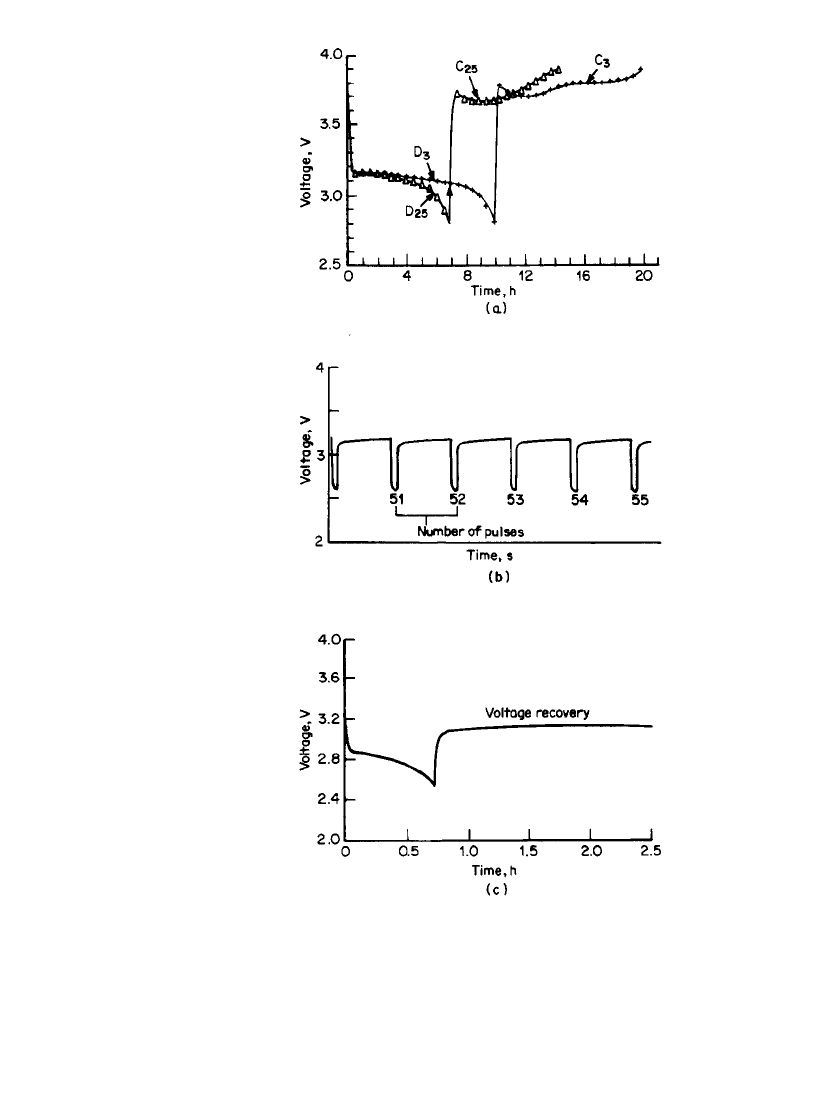
Typical discharge-charge curves of lithium/carbon batteries of 3 Ah capacity using a
LiAlCl
4
䡠 6SO
2
electrolyte are shown in Fig. 34.32a for selected cycles. The change in voltage
with time for the cell and the cathode versus the lithium reference are almost identical,
indicating little anode polarization at the 1 mA/ cm
2
discharge and charge rate. The gradual
loss of capacity and the increased charge plateau on cycling are related to cathode polari-
zation. Scanning electron microscopy and X-ray diffraction analyses of discharged cathodes
confirm that the polarization is caused by irreversible deposition of a nonconductive dis-
charge product (LiCl).
The lithium /carbon system in SO
2
-based LiAlCl
4
electrolyte has excellent shelf life (⬍1%
capacity loss per month) and insignificant voltage delay, even after 3 years of storage at
room temperature.
59
The cell delivers significantly lower capacity at low temperature. Figure
34.32c shows the discharge characteristics of a lithium/carbon cell at
⫺20⬚C. The system is
particularly suitable for high-rate pulse power applications. Figure 34.32b shows the pulse
discharge behavior of a lithium/carbon battery in LiAlCl
4
䡠 6SO
2
at 20 mA/ cm
2
.
61
Lithium/ Copper Chloride Battery. In this system, the copper chloride cathode is directly
reduced and oxidized and no lithium intercalation-deintercalation occurs during the dis-
charge-charge process. The use of CuCl
2
as the active cathode material provides a higher
discharge voltage (3.3 V) for the reduction of Cu
2
⫹
to Cu
⫹
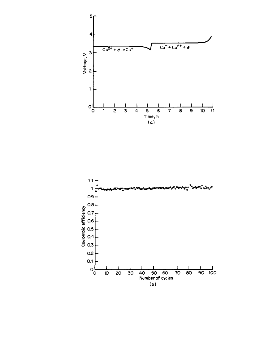
. Figure 34.33 shows the discharge-
charge behavior of a prismatic D-size Li /CuCl
2
battery at 1 mA /cm
2
. If the discharge is
limited to a single-electron process, high cycle life (
⬎200) with good capacity (0.9e /CuCl
2
)
can be achieved. This system shows excellent coulombic efficiency (see Fig. 34.33b).
34.46 CHAPTER THIRTY-FOUR
FIGURE 34.32 (a) Discharge / charge behavior of a
Li / LiAlCl
4
䡠 6SO
2
C-size battery at 1 mA / cm
2
. Voltage
limits; 2.8–4.0 V. Line—battery, symbols (䉭)—cathode
vs. ref. (b) High-rate pulse discharge of a Li / LiAlCl
4
䡠
6SO
2
C-size battery. Pulse rate at 20 mA/ cm
2
for 20 s.
Rest period for 180 s. (c) Discharge characteristics and
voltage recovery (without load) of a Li / LiAlCl
4
䡠 6SO
2
C-size battery at ⫺20⬚C. Discharge at 3.2 mA/ cm
2
.
(From Yardney Technical Products, Inc.)
RECHARGEABLE LITHIUM BATTERIES (AMBIENT TEMPERATURE) 34.47
FIGURE 34.33 (a) Discharge/ charge behavior of a Li / CuCl
2
prismatic D-size battery in LiAlCl
4
䡠 6SO
2
electrolyte at 1 mA / cm
2
.
(b) Coulombic efficiency of a Li/ CuCl
2
battery at 1 mA/ cm
2
.
(From Yardney Technical Products, Inc.)
34.48 CHAPTER THIRTY-FOUR
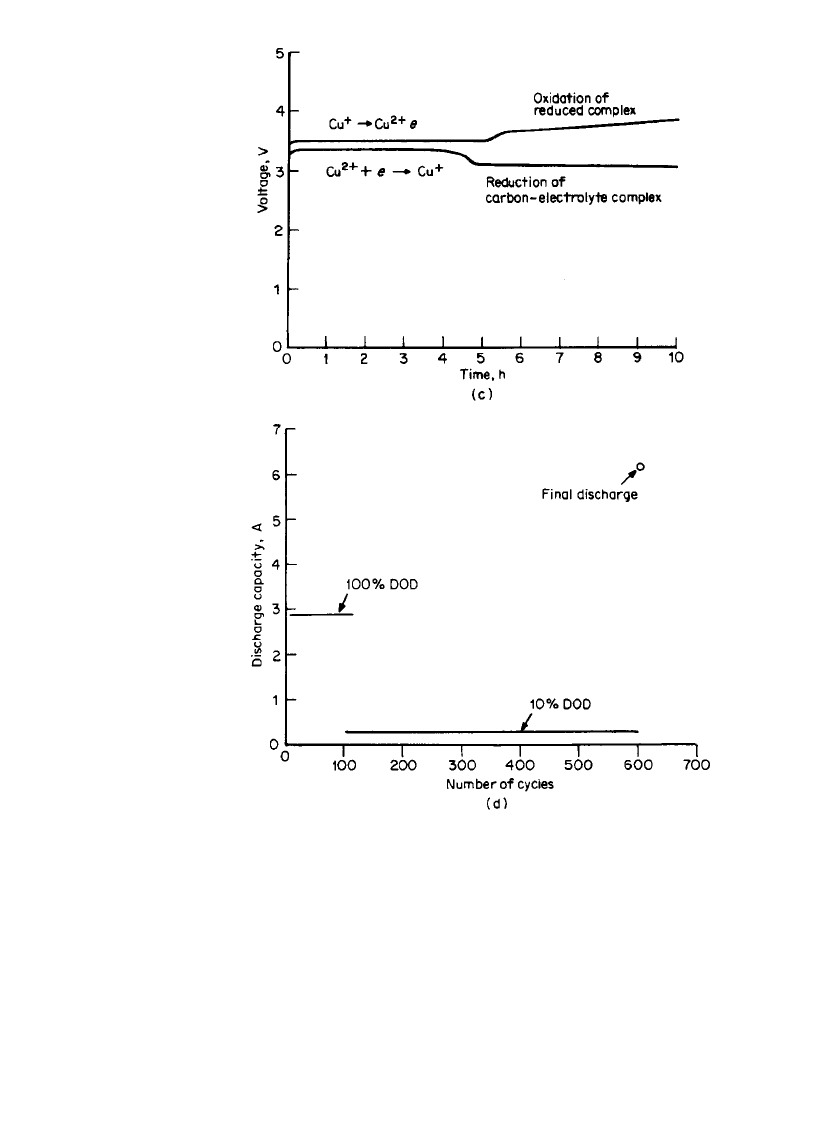
FIGURE 34.33 (c) Discharge behavior of a Li / CuCl
2
rechargeable
battery in LiAlCl
4
䡠 6SO
4
electrolyte at 1 mA / cm
2
.(d ) Cycling behav-
ior of a Li / CuCl
2
prismatic D-size battery at 1 mA/ cm
2
.(From Yard-
ney Technical Products, Inc.)(Continued ).
When an optimal combination of Ketjen black carbon and CuCl
2
is used as the cathode,
limited overdischarge-overcharge protection can be achieved. These batteries can also deliver
extra capacity when needed. The discharge-charge as well as the overdischarge-overcharge
characteristics of such a battery are shown in Fig. 34.33c. Possible cell reactions are as
follows:
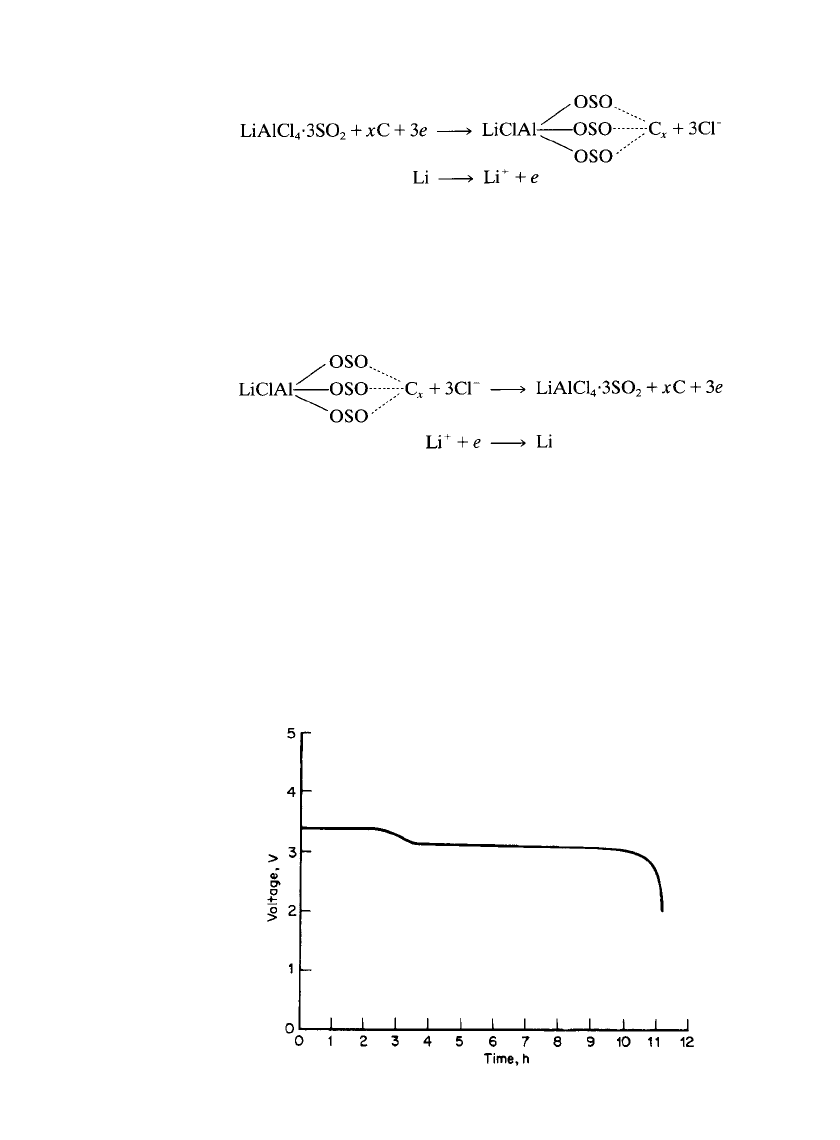
Discharge:
2
⫹⫹
Cathode: Cu ⫹ e → Cu
⫹
Anode: Li → Li ⫹ e
RECHARGEABLE LITHIUM BATTERIES (AMBIENT TEMPERATURE) 34.49
FIGURE 34.34 Discharge behavior of a Li / CuCl
2
prismatic D-
size battery after 100 cycles at 100% DOD and 500 cycles at 10%
DOD. Discharge rate at 1 mA / cm
2
.(From Yardney Technical
Products, Inc.)
Overdischarge:
Cathode
Anode
Charge:
⫹
2
⫹
Cathode Cu → Cu ⫹ e
⫹
Anode Li ⫹ e → Li
Overcharge:
Cathode
Anode
The composition of the cathode is typically 67% CuCl
2
, 25% Ketjen black, and 8% Teflon.
The cycling behavior of a Li /CuCl
2
Ketjen black prismatic D-size cell in LiAlCl
4
䡠 6SO
2
electrolyte is shown in Fig. 34.33d for the first 100 cycles at 100% depth of discharge (the
cell was cycled with time limits rather than voltage limits), then 500 cycles at 10% depth
of discharge, and finally the total discharge and overdischarge capacity of the cell (see Fig.
34.34). The extra capacity is due to the reduction of the complex formed by the SO
2
-based
LiAlCl
4
with the high-surface-area carbon.
The Li /CuCl
2
Ketjen black system in LiAlCl
4
䡠 3SO
2
electrolyte has been investigated in
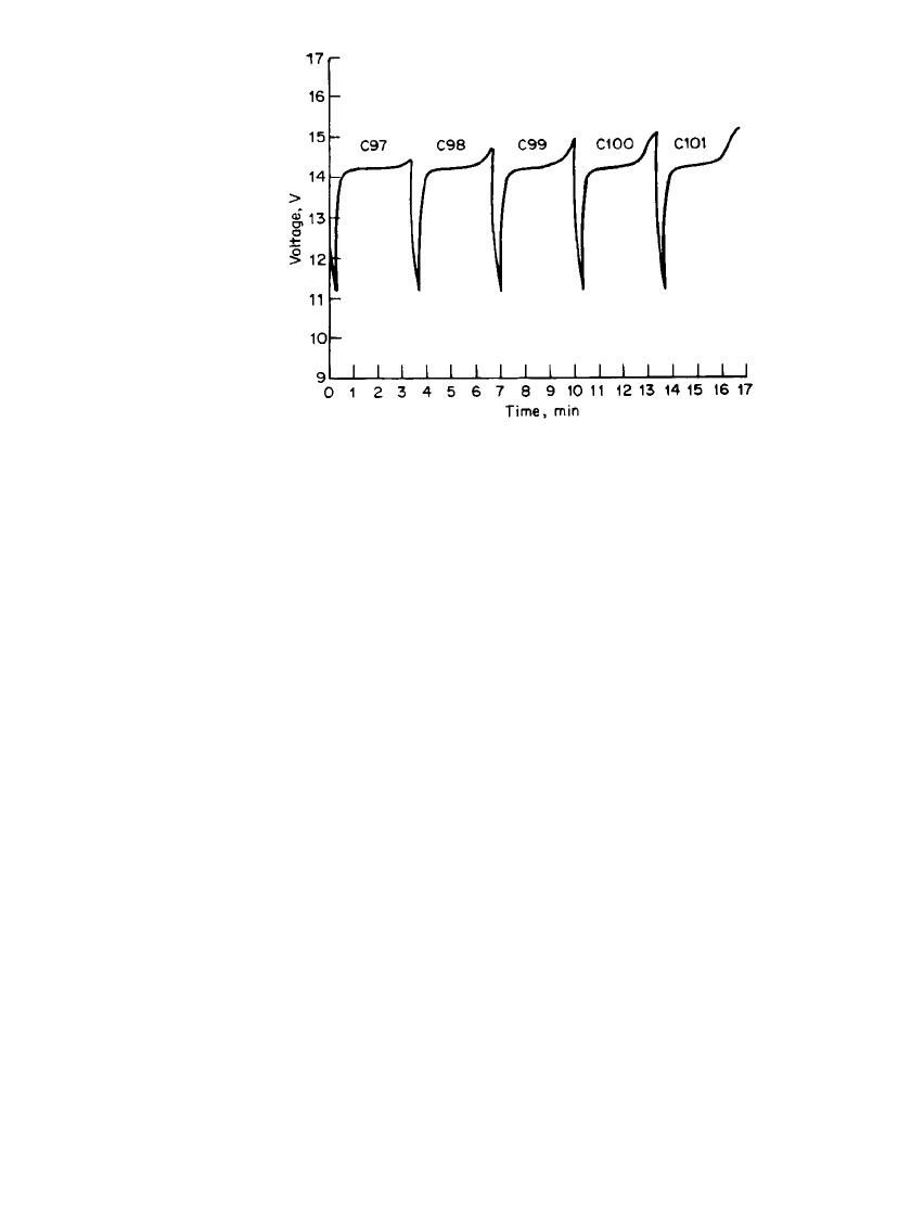
a bipolar configuration for high-rate pulse power applications. Figure 34.35 shows a portion
of the cycling behavior of a four-cell-stack bipolar battery. The battery delivered more than
1000 pulse cycles.
63
34.50 CHAPTER THIRTY-FOUR
FIGURE 34.35 Discharge/ charge behavior of a bipolar Li/
CuCl
2
battery (four-cell stack) at 50-mA / cm
2
(total 24 A) dis-
charge for 20 s and 5.56-mA / cm
2
charge for 180 s. Voltage limits:
11.0–16.0 V. (From Yardney Technical Products, Inc.)
Laboratory-scale work has continued to improve the safety and cycle-life of the Li /CuCl
2
system.
64
Design modifications and electrolyte additives are claimed to reduce the tendency
of this battery to form dendrites on overcharge, leading to internal shorts and ventings. Three
hundred charge-discharge deep-discharge cycles are claimed with these changes. The elec-
trolyte modification apparently involves the addition of chlorine, which leads to corrosion
of 300-series stainless steel case-positive cells during charging, and this ultimately limits
cycle life. Proprietary shut-down separators are also stated to be under development to im-
prove the safety of this battery system.
Although the SO
2
-based inorganic electrolyte systems have been investigated for some
time and may be of interest for special application because of their advantageous performance
characteristics, the toxicity and corrosivity of the electrolyte present a potential safety hazard
limiting commercial applications. Safety problems have also been persistent with these sys-
tems and have limited their development beyond the laboratory level.
A lithium-metal LiAlCl
4
-SO
2
/LiCoO
2
battery is currently under development.
12,65,66
This
system is built in the discharged state and is charged by plating lithium metal on a nickel
metal substitute. In this way, no excess lithium is present. The lithium electrode has been
found to have a SEI layer on lithium of lithium dithionite (Li
2
S
2
O
4
) through which the
electrochemical reactions occur.
65
Early versions of this battery used a microporous Tefzel威
separator, but this material is no longer commercially available. This system also possesses
an overcharge mechanism in which chlorine is evolved at the positive electrode above 4.5
V and reacts with excess lithium on the negative electrode. Lithium is plated in filamentary
form during charge using this electrolyte, which contains a SO
2
/LiAlCl
4
ratio of 1.5 to 1.8.
Cycling efficiencies of 98 to 99% for the lithium plating and stripping reactions have been
found in this electrolyte.
66
Prototype 7 Ah batteries are stated to provide a specific energy
of about 200 Wh/kg and reach specific power levels of 1300 W/ kg.
66
Development of this
system continues.
