Lefebvre A.H., Ballal D.R. Gas Turbine Combustion: Alternative Fuels and Emissions
Подождите немного. Документ загружается.

400 Gas Turbine Combustion: Alternative Fuels and Emissions, Third Edition
Combustion tests showed that NO
x
emissions were lowest with either total
inner fueling or combined inner and outer fueling. The combustor yielded
around 12 ppmv NO
x
at 0.6 MPa and 20 ppmv at 0.9 MPa. CO was always
below 50 ppmv. In common with most well-mixed systems, low concentrations
of both CO and NO
x
were attainable only over a fairly narrow range of operat-
ing conditions. Potential improvements for this concept include increasing the
number of fuel-injection holes used to deliver fuel to the lming surface to aid
in the formation of a more uniform lm, and lengthening the injector center-
body to allow a longer time for fuel evaporation and mixing [54].
9.7.2 Siemens Hybrid Burner
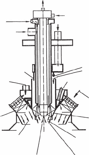
This burner was originally developed to operate on natural gas in either
diffusion or premix modes. It has two separate air passages—an inner one,
which features an axial swirler near its exit, and a concentric outer passage,
which is designated in Figure 9.24 as “diagonal swirler” because it is tilted
Fuel oil return
Fuel gas flow to the
pilot burner nozzle
Fuel gas flow to the
diffusion burner nozzle
Fuel oil
diffusion burner
Fuel gas
diffusion burner
Fuel gas
pilot burner
Axial swirler
Main air flow
Fuel gas flow to the
premixed burner nozzle
Fuel oil flow to the
premixed burner nozzle
Water injection
Main air flow
Steam or water
Fuel oil inlet
Diagonal swirler
Fuel/air mixture for the
premixed operating mode
Steam injection
Figure 9.24
Siemens hybrid burner. (From Angello, L. and Lowe, P., ASME Paper 89-GT-254, 1989; Bonzani,
F., Di Meglio, A., Pollarolo, G., Prade, B., Lauer, G., and Hoffmann, S., Presented at Power-Gen
Europe ‘97, Madrid, June 1997. With permission.)
Emissions 401
with respect to the burner axis. The inner passage, which carries about 10%
of the total air, contains the gas-diffusion and pilot burners. During startup
and low load operation, all the fuel is conned to this passage. As the load
increases, a fuel/air ratio is eventually reached at which the burner switches
from a diffusion to a premix mode. The gas is then injected into the outer
air passage through small premixer tubes (one per diagonal swirler vane
channel), each containing ten holes. This arrangement ensures a high level
of radial and circumferential uniformity in the fuel–air mixture entering the
premix combustion zone. Good stability is achieved by the presence of the
pilot burner situated in the inner passage. Essentially, the system functions
as a diffusion burner at low engine loads, and then operates as a premix
burner in the upper load range.
For liquid fuels, the burner is equipped with a central oil burner lance. A
further nozzle system for water or steam injection into the diffusion ame
ensures that NO
x
emissions can be reduced to low values over the entire
engine operating range [56].
The Siemens hybrid burner is now fully established as a low-emissions
system for engines in the 150 MW class, and has consistently achieved
single-gure NO
x
emissions levels (9 ppmv) when burning natural gas. Its
exibility has been demonstrated by its application by MAN GHH to its
THM 1304 engine. This 9 MW class gas turbine is a two-shaft, heavy frame
machine that features two tubular combustion chambers mounted on top
of the engine casing. NO
x
emissions are less than 5 ppmv between 75% and
100% load when operating on natural gas.
In the early Siemens silo combustors, all the hybrid burners were of the
same design and size. Adaptation to different combustor sizes was accom-
plished by changing the number of burners. However, in the new hybrid
burner ring (HBR) annular combustors, the number of burners is kept con-
stant at 24 in order to achieve a satisfactory temperature pattern factor (see
Chapter 4). This means that the size of the burner must be varied to suit
the size of the combustor. However, the basic hybrid burner design remains
unchanged [57].
The new annular combustor developed jointly by Siemens AG and Ansaldo
Energia in Italy for the V64.3A engine features premixed operation for both
natural gas and fuel oil. The gaseous fuel is injected into the diagonal swirl-
ers in the manner described above; the liquid fuel is injected through plain-
orice atomizers into the crossowing airstream issuing from these swirlers.
Water or steam is not required to meet the emissions regulations.
9.7.3 general electric DLN Combustor
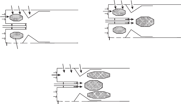
The GE DLN combustor, shown schematically in Figure 9.25, is a two-stage
concept designed for application to natural gas-red, heavy-duty gas turbines,
but capable of liquid fuel operation with diluent injection to control NO
x
. It
has been described in some detail in a number of publications, including
402 Gas Turbine Combustion: Alternative Fuels and Emissions, Third Edition
those of Maughan et al. [27], Davis and Washam [33], Hilt and Waslo [34],
Schorr [40], Davis [51], and Washam [58]. The essence of this concept is the
use of two-stage combustion to achieve low emissions and high operabil-
ity over the entire load range. The combustion system consists of four main
components: primary fuel nozzles, liner, venturi, and cap/centerbody assem-
bly. These components are arranged to provide three main zones:
1. A primary zone that extends from the six primary nozzles mounted
on the cap face to the end of the centerbody
2. A secondary zone that includes the volume from the centerbody exit
to the plane of the dilution holes
3. A dilution zone that occupies the space from the dilution holes to the
end of the liner
The combustor operates in four distinct modes, which are designated as
primary, lean-lean, secondary, and premix as described below.
9.7.3.1 Primary
As illustrated in Figure 9.25a, lightoff is accomplished with fuel owing
through the primary nozzles located in the head end of the liner. Primary
combustion air enters through swirlers surrounding each nozzle and through
the primary air holes. This mode of operation is used to ignite, accelerate,
and operate the machine at low-power settings up to around 40% full load.
Primary
fuel and
swirler
Primary
Venturl cooling
Liner venturl
Liner
Ignitor
Primary
flame zone
Secondary
fuel and
centerbody
Mixing
fuel and air
Premixed
primary
Premixed
secondary
Premixed
secondary
flame zone
(a) (b)
(c)
Jets
Figure 9.25
GE DLN combustor in various operational modes: (a) primary; (b) lean-lean; and (c) premix.
(From Maughan, J.R., Luts, A., and Bautista, P.J., ASME Paper 94-GT-252, 1994. With
permission.)
Emissions 403
9.7.3.2 Lean-Lean
As the engine load increases, fuel is supplied to the secondary zone from
four radial stub pipes located in the centerbody, as shown in Figure 9.25b.
This fuel mixes with air and then ows through a swirler at the centerbody
exit to create a swirl-stabilized secondary combustion zone. The primary and
secondary zones both operate at low equivalence ratios, hence the term lean-
lean for this operating mode, which can raise turbine output to base load.
9.7.3.3 Secondary
This mode represents a transition between lean-lean and premix modes.
The fuel supply to the primary zone is gradually reduced while increasing
the fuel ow to the secondary zone. Eventually, the primary ame is extin-
guished, leaving ame only in the secondary zone.
9.7.3.4 Premix
Fuel is reintroduced through the primary nozzles and the primary com-
bustion zone (now premixed) is shifted to a region downstream of the liner
venturi, where it is ignited by the secondary ame zone (Figure 9.25c). The
venturi consists of a converging–diverging section that accelerates the ow
from the rst stage to prevent ashback. It also creates a toroidal recirculation
zone over its downstream conical surface to stabilize the primary combustion
zone in this premix mode, which is attained at or near the engine design
point. This mode corresponds to minimum pollutant emissions.
If required, both the primary and secondary fuel injectors can be dual-fuel
nozzles, to permit automatic transfer from gas to oil throughout the load range.
The system can achieve NO
x
and CO levels of 9 and 25 ppmv, respectively, at
base load when operating on natural gas [51]. With liquid fuels, the NO
x
and
CO emissions from the DLN combustor at loads less than 20% of the base load
are similar to those obtained with the standard combustor. This result is hardly
surprising because both systems feature diffusion ames in this range. The
combustor operates in the lean-lean mode between 20 and 50% load and in the
premix mode from 50 to 100% load. NO
x
emissions are appreciably lower than
for a standard combustor due to the premixing, but are considerably higher
than the low levels achievable with gas in the fully premixed mode. With
water injection, the combustor achieves NO
x
and CO levels of 42 and 20 ppmv,
respectively, at base load when operating on distillate oil fuel [51].
9.7.4 ABB eV Burner
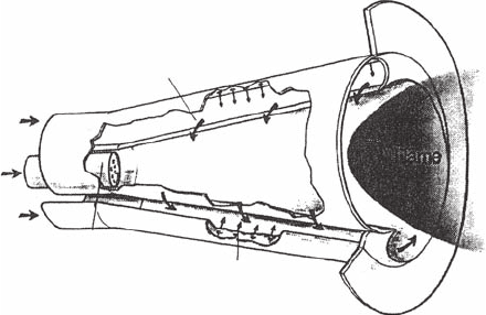
The ABB company has developed a conical premix burner module, called
the EV-burner, which has demonstrated good performance in a wide range
of DLN combustion applications [59,60]. A cross-sectional view to illustrate
404 Gas Turbine Combustion: Alternative Fuels and Emissions, Third Edition
the operating principles of the burner is given in Figure 9.26. Each burner is
formed by two offset half cones, which are shifted to form two diametrically
opposed air inlet slots of constant width. Gaseous fuels are injected into
the combustion air owing into the slots by means of two fuel distribution
tubes containing rows of small holes that inject the fuel across the airstream.
Fairly complete mixing of fuel and air is obtained shortly after injection and
the swirling mixture ows out of the cone and into the ame zone. A unique
feature of this burner is that ame stabilization is achieved in free space near
the burner outlet because of the sudden breakdown of a swirling ow.
The device can operate satisfactorily on both gaseous and liquid fuels. The
latter are injected at the apex of the cone using a pressure or air-assist type of
atomizer. The fuel is not fully evaporated by the time it reaches the stabiliza-
tion zone and a diffusion-type ame penetrates a short distance upstream
into the burner, which explains why no pilot stage is needed to achieve ade-
quate ame stability. Also, because the ame never touches the walls, the
cone body remains clean and metal temperatures are relatively low.
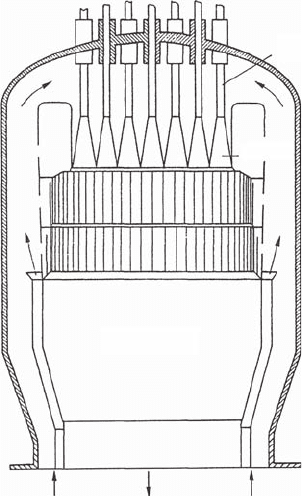
In February 1991, an ABB GT11N gas turbine was retrotted with a new silo
combustor of the type shown in Figure 9.27. This silo combustor is equipped
with 37 EV burners, all of which operate in a pure premix mode [59]. For part
load operation, fuel is supplied to only a fraction of the total number of burn-
ers. NO
x
values of 13 ppmv have been reported by Aigner and Muller [60] for
the base load conditions of 1.25 MPa and T
3
= 643 K.
When burning MBtu syngases, a different fuel-injection strategy is called
for than for natural gas because of the very high ame speeds and fast reac-
tion times of MBtu fuels [61]. Injection of the fuel along the inlet air slots is
no longer appropriate. Instead, fuel injection is delayed until the burner exit,
where it enters the swirling airstream through a number of plain holes that
direct the fuel radially inward.
Combustion air
Gas fuel stage 2
Gas fuel stage 2
Atomization
nozzle
Gas injection ports
Gas fuel stage 1
Liquid fuel
Figure 9.26
Operating principle of ABB EV conical premix burner. (From Sattelmayer, T., Felchin, M.P.,
Haumann, J., Hellat, J., and Styner, D., Journal of Engineering for Gas Turbines and Power, 114(1),
118–25, 1992. With permission.)
Emissions 405
The EV-burner technology has also been used in the design of annular
combustors. The ABB GT10 (23 MW) combustor features a single row of
18 EV burners, whereas the heavy-duty ABB GT13E2 gas turbine (>150 MW)
has 72 EV-burners that are arranged in two staggered circumferential rows
within the annular combustor [62].
In 1994, the 17 MW GT35 7-can combustor was equipped with 3 EV burn-
ers per can. It operates on gas only and startup is achieved using one burner
per can. Between idle and half load, a second burner is also used. At higher
loads, all three burners are in operation. Burner staging has a surprisingly
small effect on combustor pattern factor [63].
From the different sizes of engines and from the different types of combus-
tor (can, annular, and silo) and the number of burners employed, it is clear
that the burner modules cannot have the same size for all engines. Thus, a
major asset of the EV burner is that it can be scaled with only minor modi-
cations to suit a wide range of engine applications.
The latest engine from ABB—the GTX100—is a single shaft 43 MW
machine that features an annular combustor containing 30 AEV burners,
which represent the most recent development in EV burner technology. The
Fuel lance
Burner
Flame tube
To turbine From compressor
Figure 9.27
Silo burner tted with ABB EV burners. (From Aigner, M. and Muller, G., Journal of Engineering
for Gas Turbines and Power, 115(3), 533–6, 1993. With permission.)
406 Gas Turbine Combustion: Alternative Fuels and Emissions, Third Edition
AEV burner features an increase in the number of air inlet slots from two
to four. Gas feed pipes located along the slots inject gaseous fuel through
“tuned” holes with “tuned” spacing into the combustion air owing into
the slots. When operating at part load, gas is also injected through six equi-
spaced holes around each mixing tube exit to produce a ring of diffusion
ames with good weak extinction performance. To meet the requirement
for operation on liquid fuel, a pressure atomizer is located in the apex of
the burner cone. This atomizer provides four separate fuel sprays—one for
each slot in the burner cone. At its center is a small pilot atomizer, which
produces a narrow-angle spray of low penetration. The purpose of this pilot
nozzle is to create a small fuel-rich zone in the center of the mixing tube
exit, thereby extending the lean blowout limit. Downstream of the four cone
segments is a short transition piece whose function is to convert the four
individual fuel-airstreams into a single coherent ow. Further downstream
is a cylindrical mixing tube in which fuel evaporation and fuel–air mixing
proceed to completion. The efux from the mixing tube is then discharged
into an annular liner, where the ame is anchored in free space as in the
EV burner. The emissions performance of the AEV burner on the GTX100
engine between 50 and 100% full load is 15 ppmv NO
x
and CO on gaseous
fuel and 25 ppmv NO
x
and CO on gas oil [63].
9.7.5 rolls royce rB211 industrial Burner
Most of the operating experience gained in DLE technology has been with
heavy-duty gas turbines whose applications call for extended periods of base
load running. However, there are many other applications, such as mechani-
cal drive for pipeline compressors, where considerable operational exibility
is required. Aeroderivative engines have much to offer in this regard, and
there are a number of stationary engines in the small-to-medium-size cate-
gory that have been derived from successful high-performance aero engines.
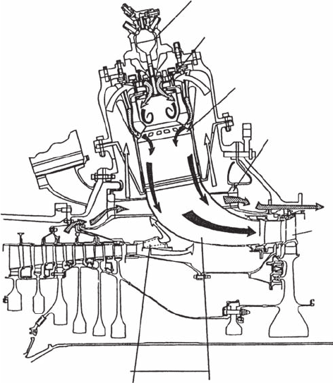
One notable example is the Rolls Royce RB211 engine in which the annular
aero-combustor has been replaced by nine radially positioned reverse ow
combustors, as shown in Figure 9.28 from Willis et al. [31]. This arrangement
results in an 80% increase in combustion volume. The primary zone is fed by
two counter-rotating air swirlers, with several gaseous fuel-injection points
located in each swirl passageway. The secondary mixing duct is wrapped
around the primary combustor, but is separated from it by another annu-
lar duct that provides the wall-cooling air. Gaseous fuel is injected into the
secondary duct from 36 equispaced axial spray bars, each containing six
injection holes. This fuel bar arrangement was determined by trajectory cal-
culations and an air velocity prole predicted by a CFD code. Fuel sampling
and combustion tests showed uniformity of fuel–air mixing to within 4%.
Combustion testing, carried out over a range of pressures from 0.1 to 2.0 MPa,
demonstrated the ability of this axially staged, DLE combustor to achieve
simultaneously low NO
x
and low CO over wide ranges of power and ambient
Emissions 407
temperature without resorting to either variable geometry or air bleeds. It
was also demonstrated that a uniform fuel distribution before combustion is
essential for achieving low emissions, especially at high pressures. Based on
the test data obtained so far, at full base load conditions the predicted engine
emissions are 17.4 ppmv NO
x
, 5 ppmv CO, and zero UHC.
9.7.6 egT DLN Combustor
The European Gas Turbine company (EGT) has adopted a simple xed-
geometry, partially premixed system for its G30 DLN combustor. The NO
x
emission goal of 25 ppmv is achieved by partially premixing the fuel with half
of the total combustor airow. Also, the incorporation of an impingement-
cooled, thermal barrier coated liner greatly reduces the wall-quenching effects
associated with conventional lm-cooled liners and limits CO and UHC emis-
sions to below 50 and 20 ppmv, respectively.
Torch igniter
Injector
Combustor
Air transfer
casing
HP turbine
Discharge
nozzle
Diffuser
Figure 9.28
Rolls Royce Industrial RB211 DLE combustor. (From Willis, J.D., Toon, I.J., Schweiger, T., and
Owen, D.A., ASME Paper 93-GT-391, 1993. With permission.)
408 Gas Turbine Combustion: Alternative Fuels and Emissions, Third Edition
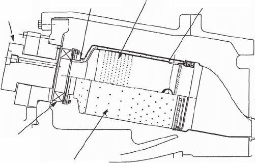
The essential features of the G30 combustor have been described by Norster
and DePietro [64] and are shown schematically in Figure 9.29. The basic
design philosophy is to achieve good mixing at high ring temperatures to
limit NO
x
production, and relatively poor mixing at lower temperatures to
give a good stability margin and low CO/UHC emissions.
The tubular combustor incorporates a simple radial inow swirler, a
swirler slot fuel-injection system, and a premixing chamber, all of which
are attached to the upstream end of the main barrel of the combustor. These
components provide major control of combustion air, fuel injection, and
mixing. Ignition and ame stabilization occurs within the vortex core of
the prechamber. Gaseous fuel is injected at the entrance of each swirler slot
through a metering jet that is sheltered below a step on the upstream side
of the slot. At low fuel ows, corresponding to low ring temperatures, the
injected fuel remains close to the rear wall of the slot and delivers a poorly
mixed fuel–air mixture to the prechamber. With increasing fuel ow, the
fuel penetrates further across the swirler slot and mixes more effectively
with the swirler air, thereby providing a more uniform mixture to the burn-
ing zone.
During starting and engine acceleration, there is a need for a piloting ame
of high stability and efciency. This is provided by a pilot/igniter burner,
which is centrally located in the head of the prechamber (see Figure 9.29). The
amount of fuel supplied to the pilot under starting and acceleration conditions
is adjusted automatically to achieve smooth and consistent starting. At full
engine speed, with no load or low ring temperature, the pilot fuel proportion
Main
swirler
Impingement
liner
Piolt
burner
Premix
chamber
Softwall
Plunged dilution
hole
Figure 9.29
EGT dry low-emissions combustor. (From Norster, E.R. and DePietro, S.M., Institution of Diesel
and Gas Turbine Engineers, DEUA Publication 495, 1996; Gallimore, S., Vickers, R.M, and Boyns,
M.B., ASME Paper 97-GT-159, 1997. With permission.)
Emissions 409
is fairly high (around 50%) to assist ame stability at these fuel-lean condi-
tions. This proportion is gradually reduced with an increase in ring tempera-
ture and reaches a minimum value at full load.
The G30 combustor was designed and developed initially for the 4.9 MW
Typhoon gas turbine. It is intended to be retrotable across EGT’s Typhoon/
Tornado/Tempest range of small engines (<10 MW). Base load emissions
of below 15 ppmv NO
x
and 10 ppmv CO, along with zero UHC, have been
achieved on the Tornado single-shaft industrial engine [65].
9.7.7 general electric LM6000 Combustor
Another important aeroderivative gas turbine is General Electric’s LM6000.
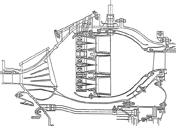
Figure 9.30 gives a cross-sectional view of the DLN combustor designed for
this engine, as described by Leonard and Stegmaier [19] and Joshi et al. [66].
This premix combustor employs about twice the volume of the conventional
annular combustor it replaces in order to maintain low levels of CO and UHC
while greatly reducing the emissions of NO
x
. Part of the air used in combus-
tion, which at maximum power is around 80% of the total combustor airow,
ows into the combustion zone through three annular rings of premixers, as
shown in Figure 9.30. The two outer rings each have 30 fuel–air premixers,
whereas the inner ring has 15. This arrangement of premixers facilitates fuel
staging at part-load operation. The total of 75 fuel nozzles is formed by hav-
ing 15 stems with three premixers on each stem, as shown in Figure 9.31, plus
Figure 9.30
General Electric LM6000 dry low-NO
x
combustor. (From Leonard, G. and Stegmaier, J., Journal
of Engineering for Gas Turbines and Power, 116, 542–6, 1993. With permission.)
