Lefebvre A.H., Ballal D.R. Gas Turbine Combustion: Alternative Fuels and Emissions
Подождите немного. Документ загружается.

250 Gas Turbine Combustion: Alternative Fuels and Emissions, Third Edition
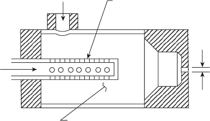
Most of the research carried out on effervescent atomization [36–43] has
used atomizers of the plain-orice type shown in Figure 6.22. A drawback
to this simple concept is that the spray cone angle is fairly small, typically
around 20° [43]. Most gas turbine combustors require injectors that distrib-
ute the fuel in the form of a conical spray of approximately 90° included
angle. Whitlow et al. [41] have studied several different types of efferves-
cent atomizers designed to produce wide-angle sprays. One design was
essentially the same as the atomizer shown in Figure 6.22, except that the
single-hole orice was replaced with four equispaced holes drilled at an
angle of 40° from the axis of the mixing tube. Tests carried out on this four-
hole design showed that the total liquid ow was uniformly distributed
between the four holes to within a few percent. Using four holes instead of
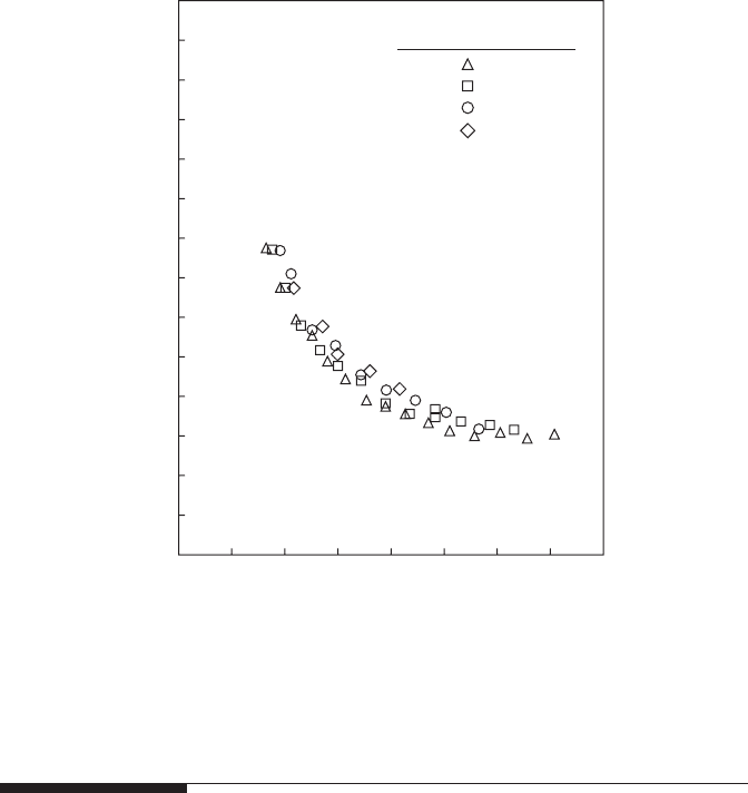
one had no deleterious effect on atomization quality, as Figure 6.23 clearly
shows.
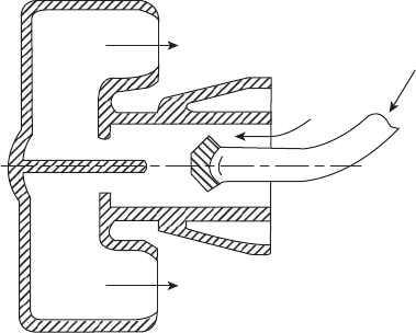
Whitlow et al. also found that a wide-angled spray could be produced
by replacing the normal circular discharge orice with a suitably angled
annular passage. With this arrangement, the two-phase mixture is ejected
from the atomizer in the form of a hollow-cone spray, with most of the
droplets concentrated around the outer periphery. One of the advantages
of this simple conguration is that the annular discharge passage can be
designed to produce a hollow-cone spray having virtually any desired
spray angle. The performance of this type of conical-sheet effervescent
atomizer was investigated over wide ranges of pressure, air/liquid ratio,
and annular gap width. A satisfactory and stable spray was observed at all
operating conditions.
More detailed information on the design aspects of various types of
effervescent atomizers, including single-hole, multi-hole, conical-spray, and
annular spray, may be found in References [42] and [44].
d
o
Air injection
holes
Region of
bubbly flow
Liquid
Air
or
gas
Figure 6.22
Plain-orice effervescent atomizer.
Fuel Injection 251
6.12 Vaporizers
Apart from the various atomization methods already discussed, an alterna-
tive method of preparing a liquid fuel for combustion is by heating it above
the boiling point of its heaviest hydrocarbon ingredient, so that it is entirely
converted to vapor before combustion. This method is, of course, applicable
only to such high-grade fuels as can be completely vaporized, leaving no
solid residue (see Chapter 1).
An alternative and much simpler method of vaporization is to inject the
fuel, along with some air, into tubes that are immersed in the ame. The
injected fuel–air mixture is heated by the tube walls and, under ideal condi-
tions, emerges as a mixture of vaporized fuel and air. The remainder of the
combustion air is admitted through apertures in the liner wall and reacts
with the fuel–air mixture issuing from the tubes.
Operating pressure, kPa
4-hole orifice
bubbly flow regime
689
140
120
SMD, µm
100
80
60
40
20
0
0 0.01 0.02
Air/liquid mass ratio
0.03 0.04
552
414
276
Figure 6.23
Inuence of injection pressure and air/liquid ratio on mean drop size. (From Whitlow, J.D.,
Lefebvre, A.H., and Rollbuhler, J.R., Fuels and Combustion Technology for Advanced Aircraft
Engines, AGARD Conference Proceedings, 536, 38, 1993.)
252 Gas Turbine Combustion: Alternative Fuels and Emissions, Third Edition
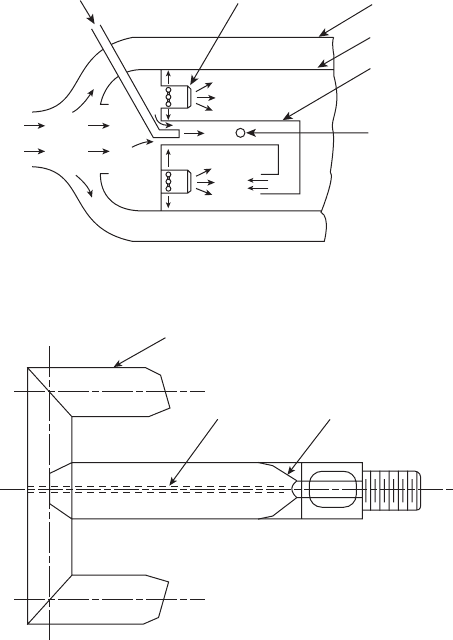
Some of the early designs, one of which is illustrated in Figure 6.24, were
generally known as “walking stick” or “candy cane” vaporizers. They
were used on the Mamba, Sapphire, and Viper engines in the UK, and
on the Curtiss-Wright J65 and Westinghouse J46 in the United States. The
Lycoming Τ vaporizer, shown in Figure 6.25, incorporates a splitter that runs
down the center of the inlet leg and, in effect, converts the vaporizer into two
back-to-back “walking sticks” sharing a common inlet. SNECMA and Rolls
Royce developed this concept further and made it suitable for application
to high-performance engines. The RR design for the RB199 engine is shown
in Figure 6.26. Note in this gure that the fuel tube has a bifurcated end to
ensure that equal amounts of fuel are supplied to both arms of the Τ vapor-
izer. The AFR within the tubes varies from around 6 at idling conditions to
between 2 and 3 at maximum power.
Casing
Liner
Vaporizing
tube
Turbulence
pin
Air “hat”
Fuel
Air
Figure 6.24
“Walking stick” vaporizing system.
Exit leg
Splitter
Fuel jet
Figure 6.25
Lycoming Τ vaporizer. (Reproduced by permission of Lycoming Engines, a div. of Avco
Corporation.)
Fuel Injection 253
Vaporizing systems have useful advantages in terms of low cost, mod-
est fuel-pump pressure requirements, and fairly low soot formation. Their
drawbacks include risk of thermal damage to the vaporizing elements and
sensitivity to variation in fuel type. Moreover, during the starting cycle, the
tubes are too cold to effect vaporization and a torch igniter is needed to initi-
ate combustion. Usually, this takes the form of a plain-orice, pressure-jet
atomizer adjacent to an igniter plug. A further drawback is that during rapid
engine acceleration the sudden addition of more fuel can overcool the tubes,
thereby lowering evaporation rates and reducing combustion efciency.
It is now widely recognized that the term vaporizer is largely a misnomer
because at high-power conditions the heat transferred to the tubes is insuf-
cient to vaporize more than a small fraction of the fuel. Thus, only at the lowest
fuel ows can the system be regarded as a true vaporizer. Where vaporizers are
used on modern engines, their main function appears to be that of providing a
satisfactory distribution of fuel throughout the primary combustion zone.
Vaporizing systems are now in service on a number of Rolls Royce engines,
including the Pegasus, Olympus, and RB199. Useful descriptions of these can
be found in papers by Parnell and Williams [45], Low [46], Sotheran [47], and
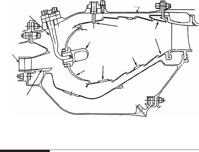
Jasuja and Low [48]. A typical modern vaporizing combustor is shown in
Figure 6.27.
In regard to future applications, it is important to bear in mind that vapor-
izer elements survive only because they are fuel-cooled. This can be a prob-
lem during rapid engine decelerations when the fuel is cut off quickly and
the only available coolant is the combustor inlet air, which, temporarily at
least, is still at a high temperature. As engine pressure ratios continue to rise,
and combustor inlet air temperatures along with them, the cooling effective-
ness of this air will diminish correspondingly. This clearly has important
implications for the mechanical integrity of any future vaporizer design.
Fuel
Air
Figure 6.26
RB 199 vaporizer. (Courtesy of Rolls Royce plc.)
254 Gas Turbine Combustion: Alternative Fuels and Emissions, Third Edition
6.13 Fuel Nozzle Coking
This problem is by no means new, but it is becoming especially serious for
advanced turbojet engines because of the growing use of fuel as a heat sink
for cooling the airframe, avionics, and engine lubricating oil. It is further
exacerbated by the fact that the fuel feed arm is immersed in the compressor
efux air. This high-pressure, high-velocity airow causes convective heat-
ing, which further raises the temperature of the fuel before it ows into the
fuel injector. The combined effect of all these various inputs is that by the
time the fuel is sprayed into the combustion zone, its temperature is appre-
ciably higher than when it left the fuel tank.
From a combustion viewpoint, this elevation in fuel temperature is not
altogether undesirable because it reduces fuel viscosity, thereby promoting
ner atomization. Unfortunately, high fuel temperatures stimulate oxidation
reactions, which lead to the formation of gums and other insoluble materi-
als (including carbon) that tend to deposit on the walls of the passages and
metering orices within the nozzle. The rate of deposition is governed mainly
by fuel temperature, but is also enhanced by an increase in wall temperature
[49,50]. These deposits can distort the fuel spray and create appreciable non-
uniformities in spray patternation [51,52].
The problems created by the deposition of carbonaceous materials, gener-
ally referred to as “coke,” within the fuel nozzle are of special importance
for pressure-swirl nozzles because they contain small internal passages that
Scoop
Fuel feed pipe
Compressor
outlet guide vane
Prediffuser
Shoulder ring
Combustion
chamber
Primary
ports
Dilution
ports
Hotshot
injector
Turbine entry
duct (TED)
Nozzle
guide
vane
Combustion chamber
outer casing
Baseplate
Vaporiser
“Blown ring”
Inner casing
Figure 6.27
Modern vaporizing combustor. (Courtesy of Rolls Royce plc.)
Fuel Injection 255
are especially prone to plugging and blockage. Coke agglomerates, formed
either upstream of the nozzle tip or within the nozzle itself, can break off
and be carried into the metering passages. Airblast atomizers are inherently
less susceptible than pressure-swirl atomizers to the problems of fuel coking
because they employ much larger fuel passages in the nozzle tip. However,
the inability of airblast atomizers to always meet the requirements of cold
day starting has prevented pure airblast systems from completely displacing
pressure-swirl atomizers from engine designs.
The effects of partially or totally blocked fuel metering passages on the
fuel-air distributions produced by an airblast atomizer have been examined
by McCaldon et al. [52]. They found that as more and more fuel metering holes
are obstructed with increasing operating time, more fuel is forced through
the remaining nozzles. Consequently, engine damage may be caused by
those injectors that, if tested individually, still ow within tolerances.
In recent years, the U.S. Naval Air Propulsion Center has sponsored an
Innovative High-Temperature Fuel Nozzle Program with the objective of
designing and evaluating fuel nozzles capable of operating satisfactorily
despite extreme fuel and air inlet temperatures. As part of this program,
Stickles et al. [53] evaluated 27 different nozzle designs, all of which were
based on the production GE F404 fuel nozzle. Heat transfer analysis high-
lighted the following design rules for reducing wetted-wall temperatures:
1. Reduce fuel ow passage area to increase fuel velocity
2. Add air gaps
3. Substitute ceramics for metal parts
4. Avoid bends and steps in the fuel ow path
Sample tube coking test results showed the importance of surface nish on the
fuel coking rate. Reducing the surface roughness from 3.1 to 0.25 µm reduced
the deposition rate by 26%. In summary, Stickles et al. found that reduced
passage ow area, reduced surface roughness, additional insulating air gaps,
and replacement of metallic tip components with ceramics, minimized the
wetted-wall temperature, thereby reducing the rate of deposition.
Thermal modeling studies carried out by Myers et al. [54] as part of the same
U.S. Navy program showed that the two major sources of heat absorption into
the fuel nozzle are the air swirler vanes and any surface exposed to the ame.
At an altitude cruise condition, for example, the predicted heat ux enter-
ing the nozzle face from ame radiation is more than 20 times that absorbed
by conduction and convection through the burner feed arm. The frontal area
exposed to the ame is thus a key element in nozzle thermal loading.
Myers et al. concluded that substantial reductions in wetted-wall tempera-
tures can be realized at extreme fuel and air inlet temperatures by using
simple air gaps as thermal barriers. Detailed thermal analysis and simple
thermal barriers, rather than exotic cooling schemes, can produce dramatic
improvements in thermal protection.

256 Gas Turbine Combustion: Alternative Fuels and Emissions, Third Edition
The problem of fuel coking and its strong adverse effects on spray uni-
formity and pollutant emissions is one of growing concern because of the
anticipated gradual deterioration in fuel quality and the continuing trend
toward higher temperature engines.
6.14 Gas Injection
Provided that their energy density is reasonably high (say not less than 6 MJ/
m
3
), gaseous fuels present no special problems, at least from a combustion
standpoint. They are usually characterized by clean combustion, with low rates
of formation of soot and nitric oxides. The main problem is that of achieving the
optimal level of mixing in the combustion zone. A mixing rate that is too high
produces narrow stability limits, but a mixing rate that is too low may make
the system prone to combustion-induced pressure oscillations. On engines
designed to operate on both gaseous and liquid fuels, it is important that the gas
ow pattern be matched to that of the liquid fuel; otherwise, some variation in
the temperature distribution of the outlet gases could occur during the change-
over from one fuel to the other. During this period, careful control over the liq-
uid and gas ow rates is required to avoid ame blowout or overtemperature.
Many different methods have been used to inject gas into conventional
combustion chambers, including plain orices, slots, swirlers, and venturi
nozzles. Good descriptions of these methods can be found in Winterfeld
et al. [55]. The various methods of gas injection employed in modern low-
emissions combustors are described in Chapter 9.
6.15 Equations for Mean Drop Size
For any given atomizer type, mean drop sizes are largely dependent on
atomizer size, design features, and operating conditions. Atomization qual-
ity is also highly dependent on the physical properties of the fuels employed
and on the properties of the surrounding gaseous medium.
The three fuel properties of relevance to atomization are density, surface
tension, and viscosity. In practice, the signicance of density for atomization
performance is diminished by the fact that most gas turbine fuels exhibit
only minor differences in this property. Surface tension is important in atom-
ization because it resists the formation of new surface area, which is fun-
damental to the atomization process. Whenever atomization occurs under
conditions where surface tension is important, the Weber number is a use-
ful dimensionless parameter for correlating drop-size data. From a practical
Fuel Injection 257
standpoint, viscosity is the most important fuel property. An increase in vis-
cosity lowers the Reynolds number of the ow inside the atomizer, thickens
the fuel sheet produced at the atomizer exit, opposes the development of
instabilities in the fuel jet or sheet, and generally delays the onset of atomi-
zation. This delay causes atomization to occur further downstream from the
nozzle where conditions are less conducive to the production of small drops.
Another important practical consideration is that although the variations
normally encountered in surface tension are only about 15%, the correspond-
ing variations in viscosity are more than an order of magnitude.
The most important air property inuencing atomization is density.
With air-assist and airblast atomizers, if breakup occurs by the classical
mechanism, an increase in air density generally improves atomization by
raising the Weber number. With pressure-swirl atomizers, the effect of an
increase in ambient air density on atomization is more complex. The con-
comitant increase in the Weber number is again benecial, but this effect is
opposed by a decrease in spray cone angle, which reduces the interaction
between the developing sheet and the surrounding air, and increases the
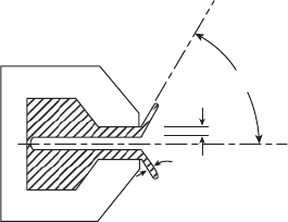
initial sheet thickness (see Figure 6.28). Furthermore, an increase in air den-
sity reduces the breakup length, so that breakup occurs closer to the nozzle
where the fuel sheet is thicker. As SMD is proportional to the square root of
the sheet thickness at breakup, the increase in sheet thickness produced by
these two separate effects acting together must result in larger drops. Thus,
an increase in air density can either raise or lower the SMD depending on
whether the benecial effect of increasing the Weber number outweighs the
adverse effect of the increase in sheet thickness. Usually, it is found that if the
ambient air density is increased continuously from its normal atmospheric
level, the cone angle gradually falls until a value of density is reached beyond
which there is no further reduction in the cone angle [56,57]. Moreover, as the
breakup length declines with increase in air density, a condition is eventually
reached where breakup occurs directly at the nozzle exit, or even within the
nozzle itself. Beyond this point, sheet thickness has little or no effect on mean
drop size. The net effect of all these separate inuences is that drop sizes
generally increase with ambient air density up to a maximum value (which
t
s
= t cosθ
t
s
t
θ
Figure 6.28
Relationship between sheet thickness and spray cone angle.

258 Gas Turbine Combustion: Alternative Fuels and Emissions, Third Edition
roughly corresponds to the condition at which the breakup length becomes
zero) and then slowly decline with further increases in air density [57].
Unfortunately, the physical processes involved in atomization are not
sufciently well understood for mean diameters to be expressed in terms
of equations derived from rst principles. In consequence, the majority of
investigations into the drop-size distributions produced in atomization have
been empirical in nature and have resulted in empirical equations for mean
drop size. The most authentic of these equations are those in which mean
drop size is expressed in terms of dimensionless groups, such as Reynolds
number, Weber number, or Ohnesorge number.
Most of the mean drop-size equations published before the 1970s should be
regarded as suspect because of deciencies in the methods available for drop-
size measurements. Even equations based on accurate experimental data
should only be used within the ranges of air properties, liquid properties, and
atomizer operating conditions employed in their derivation. Extrapolation to
other conditions is fraught with risk because changes in any of these vari-
ables could produce a change in the mode of atomization, which could have
a signicant effect on the manner and extent to which variations in the rel-
evant ow parameters affect the drop-size distributions in the spray.
The following equations for SMD have been selected from the large
number available in the literature. More detailed information on drop-size
equations for all types of atomizers may be found in Lefebvre [58].
6.16 SMD Equations for Pressure Atomizers
6.16.1 Plain Orifice
With this device, a simple circular orice is used to inject a round jet of high-
velocity liquid into the surrounding air or gas. Finest atomization is achieved
with small orices but, in practice, the difculty of keeping liquids free from
foreign particles usually limits the minimum orice size to around 0.3 mm.
Due to the formidable problems involved in making drop-size measure-
ments in the dense sprays produced by plain-orice nozzles, few equations
for mean drop size have been published. According to Elkotb [59]
SMD3.08
LLAL
=
(
)
∆
−
υ
0 385
0 737
006054.
.
..
.σρ ρ P
(6.20)
6.16.2 Pressure Swirl
In this type of nozzle, a circular outlet orice is preceded by a swirl chamber
that causes the liquid to emerge from the nozzle as an annular sheet, which
spreads radially outward to form a hollow conical spray. Despite its appar-
ent simplicity, the various physical phenomena involved in pressure-swirl

Fuel Injection 259
atomization are highly complex. For most of the past half century, mean
drop sizes have been correlated using empirical equations of the form
SMDconstant
LL L
=
−
σµ
ab cd
mP
∆ .
(6.21)
For example, Radcliffe’s equation [60] is
SMD
L
0.2
LLL
=
−−
73
06 02 02504
.,
....
σµρ
m ∆
(6.22)
whereas subsequent work by Jasuja [61] yielded the expression
SMD
LL LL
=
−−
44
06 016016 022043
..
.. .. .
σµ ρ
mP∆
(6.23)
It is noteworthy that in the experiments of Radcliffe and Jasuja, the variation
in surface tension was quite small and was accompanied by wide variations
in viscosity. Thus, the surface tension exponent of 0.6 has no special signi-
cance in Equations 6.22 and 6.23.
Another example of this type of equation, which has an advantage over
most others in that it is dimensionally correct, is the following [58]:
SMDP
0.25
LL LA
=∆
−−
225
025025 05 025
..
.. ..
σµ
m ρ
(6.24)
It is now generally accepted that for both pressure and airblast nozzles, the
relative velocity between the liquid and the surrounding air has a profound
effect on atomization. It generates the protuberances on the liquid surface
that are a prerequisite to atomization and also furnishes the energy needed
to convert these protuberances into ligaments and then drops. However,
another important factor in atomization, as discussed above, is the contribu-
tion made to sheet or jet disintegration by the instabilities created within the
liquid itself, which are very dependent on liquid velocity. In airblast atomi-
zation, where high-velocity air impacts on a slow-moving liquid, the only
factor promoting atomization is the relative velocity between the air and the
liquid. This is equally important in pressure atomization but, by achieving
this relative velocity through liquid motion instead of air motion, an impor-
tant advantage is gained in that the liquid now makes an additional and
independent contribution to its own disintegration, an effect that is either
absent or negligibly small in airblast and air-assist atomization.
These arguments highlight the special importance of velocity in pressure
atomization. The velocity at which the liquid is discharged from the noz-
zle has two separate effects on atomization. One important effect, which is
dependent on the absolute velocity U
L
, is in generating the turbulence and
instabilities within the liquid stream that contribute to the rst stage of the
atomization process. The other effect, which depends on the relative velocity
U
r
, is in promoting the atomization mechanisms that occur on the liquid
surface and in the adjacent ambient air.
