Kutz M. Handbook of materials selection
Подождите немного. Документ загружается.

4 FRACTURE MECHANICS AND UNSTABLE CRACK GROWTH 719
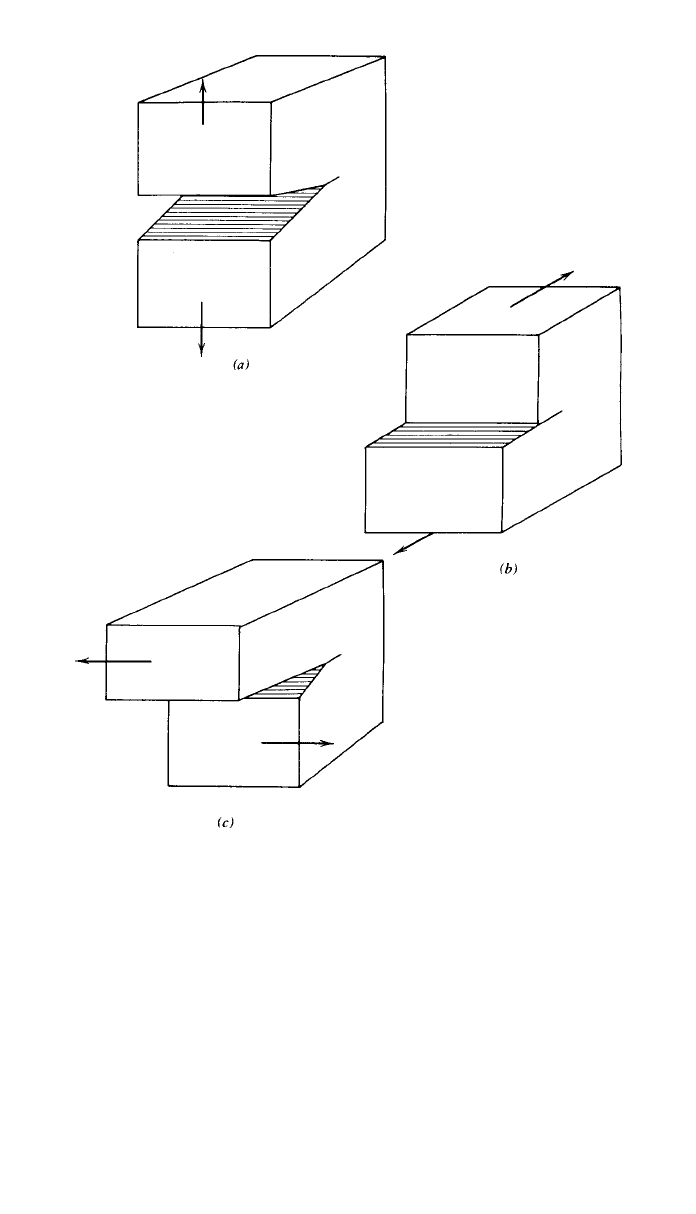
Fig. 5 Basic modes of crack displacement: (a) mode I, (b) mode II, and (c) mode III.
the type of loading and the geometry away from the crack. Much work has been
completed in determining values of C for a wide variety of conditions. (See, for
example, Ref. 5.)
Many commercial finite-element analysis software packages possess special
crack-tip elements allowing the numerical computation of stress intensity factors.
A discussion of some of the techniques employed within these software packages
is given by Anderson.
4
Through the use of weight functions,
6,35
stress intensity
factors may also be computed easily using numerical integration and the stresses
that would exist in the uncracked body.
From Eq. (9), the stress intensity factor increases proportionally with gross
nominal stress
and also is a function of the crack length a. The value of K
I
associated with the onset of fracture has been designated the critical stress in-
tensity, K
C
. As noted earlier in Figs. 3 and 4, the fracture of specimens with
720 FAILURE MODES
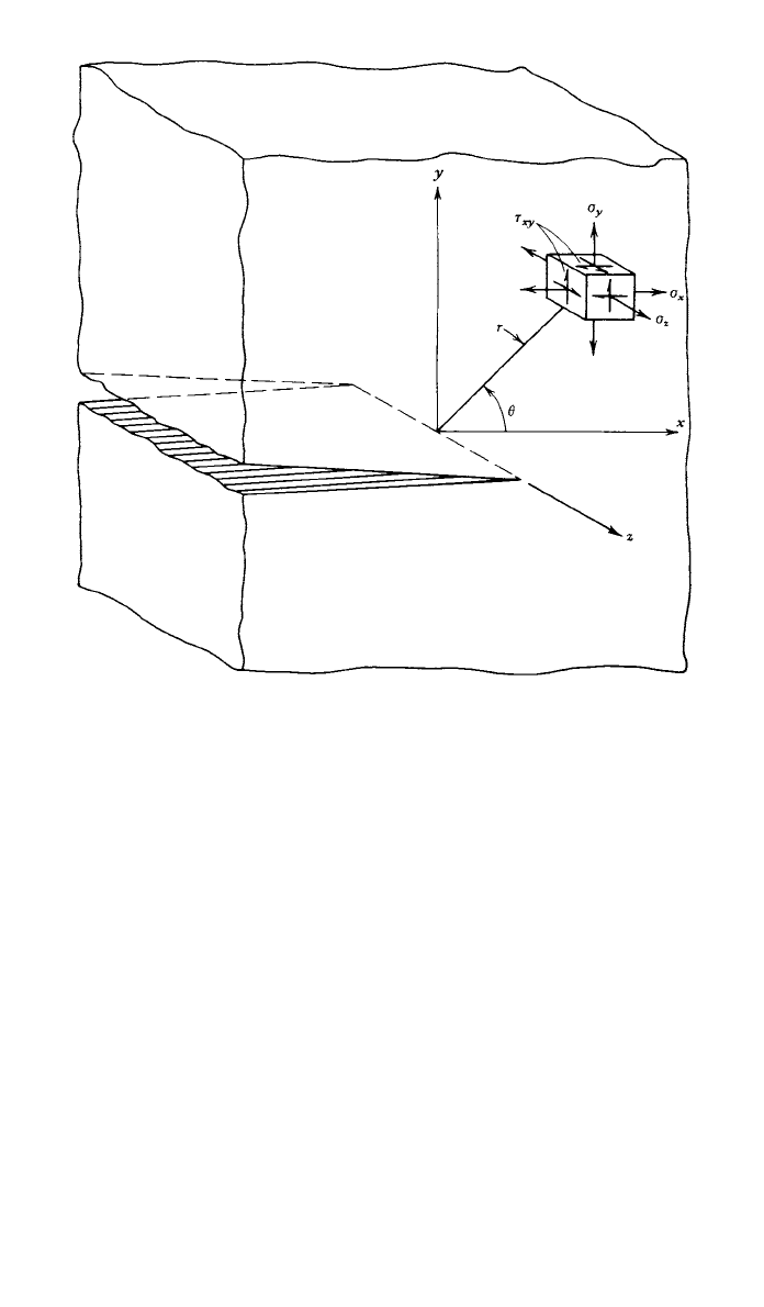
Fig. 6 Coordinates measured from leading edge of a crack.
different crack lengths occurs at different values of gross-section stress, but at a
constant value of K
C
. Thus, K
C
provides a single-parameter fracture criterion
that allows the prediction of fracture based on (9). That is, fracture is predicted
to occur if
K
ⱖ K (10)
IC
In studying material behavior, one finds that for a given material, as the
specimen thickness is increased, the critical stress intensity K
C
decreases to a
lower limiting value. This lower limiting value defines a basic material property
K
IC
, the plane-strain fracture toughness for the material. Standard test methods
have been established for the determination of K
IC
values.
7
A few data are shown
in Table 1. Useful compilations of fracture toughness values have been prepared
by several organizations and individuals. These include Refs. 9–15.
For the plane-strain fracture toughness K
IC
to be a valid failure prediction
criterion for a specimen or a machine part, plane-strain conditions must exist at
the crack tip; that is, the material must be thick enough to ensure plane-strain
conditions. It has been estimated
7
empirically that for plane-strain conditions
the minimum material thickness B must be

721
Table 1 Yield Strength and Plane-Strain Fracture Toughness Data for Selected Engineering Alloys
8,9
Alloy Form
Test
Temperature
⬚F ⬚C
yp
ksi MPa
K
IC
ksi兹in MPa兹m
4340 (500⬚F temper) steel Plate 70 21 217–238 1495–1640 45–57 50–63
4340 (800
⬚F temper) steel Forged 70 21 197–211 1360–1455 72–83 79–91
D6AC (1000
⬚F temper) steel Plate l70 21 217 1495 93 102
D6AC (1000
⬚F temper) steel Plate ⫺65 ⫺54 228 1570 56 62
A 538 steel 250 1722 100 111
2014-T6 aluminum Forged 75 24 64 440 28 31
2024-T351 aluminum Plate 80 27 54–56 370–385 28–40 31–44
7075-T6 aluminum 85 585 30 33
7075-T651 aluminum Plate 70 21 75–81 515–560 25–28 27–31
7075-T7351 aluminum Plate 70 21 58–66 300–455 28–32 31–35
Ti-6Al-4V titanium Plate 74 23 119 820 96 106

722 FAILURE MODES
2
K
IC
B ⱖ 2.5 (11)
冉冊
yp
where
yp
is the material yield strength.
If the material is not thick enough to meet the criterion of (11), plane stress
is a more likely state of stress at the crack tip; and K
C
, the critical stress intensity
factor for failure prediction under plane stress conditions, may be estimated
using a semiempirical relationship
16
:
41/2
1.4 K
IC
K ⫽ K 1 ⫹ (12)
冋冉冊册
CIC
2
B
yp
As long as the crack-tip plastic zone remains in the regime of small-scale yield-
ing, this estimation procedure provides a good design approach. For conditions
that result in large crack-tip plastic zones (large applied stresses, large crack
lengths), performing a failure assessment using linear elastic fracture mechanics
(LEFM) is invalid and potentially nonconservative. A general rule of thumb is
that plasticity effects become significant when the applied stresses approach 50%
of the yield stress, but this is by no means a universal rule.
4
When small-scale
yielding is not generated at the crack tip, a better design approach would involve
the implementation of an appropriate elastic-plastic fracture mechanics (EPFM)
procedure.
5 FATIGUE
Static or quasi-static loading is rarely observed in modern engineering practice,
making it essential for the designer to address himself or herself to the impli-
cations of repeated loads, fluctuating loads, and rapidly applied loads. By far,
the majority of engineering design projects involve machine parts subjected to
fluctuating or cyclic loads. Such loading induces fluctuating or cyclic stresses
that often result in failure by fatigue.
Fatigue failure investigations over the years have led to the observation that
the fatigue process actually embraces two domains of cyclic stressing or straining
that are significantly different in character, and in each of which failure is prob-
ably produced by different physical mechanisms. One domain of cyclic loading
is that for which significant plastic strain occurs during each cycle. This domain
is associated with high loads and short lives, or low numbers of cycles to produce
fatigue failure, and is commonly referred to as low-cycle fatigue. The other
domain of cyclic loading is that for which the strain cycles are largely confined
to the elastic range. This domain is associated with lower loads and long lives,
or high numbers of cycles to produce fatigue failure, and is commonly referred
to as high-cycle fatigue. Low-cycle fatigue is typically associated with cycle
lives from 1 up to about 10
4
cycles. Fatigue may be characterized as a progres-
sive failure phenomenon that proceeds by the initiation and propagation of
cracks to an unstable size. Although there is not complete agreement on the
microscopic details of the initiation and propagation of the cracks, processes of
reversed slip and dislocation interaction appear to produce fatigue nuclei from
which cracks may grow. Finally, the crack length reaches a critical dimension

5 FATIGUE 723
and one additional cycle then causes complete failure. The final failure region
will typically show evidence of plastic deformation produced just prior to final
separation. For ductile materials the final fracture area often appears as a shear
lip produced by crack propagation along the planes of maximum shear.
Although designers find these basic observations of great interest, they must
be even more interested in the macroscopic phenomenological aspects of fatigue
failure and in avoiding fatigue failure during the design life. Some of the macro-
scopic effects and basic data requiring consideration in designing under fatigue
loading include:
1. The effects of a simple, completely reversed alternating stress on the
strength and properties of engineering materials
2. The effects of a steady stress with a superposed alternating component,
that is, the effects of cyclic stresses with a nonzero mean
3. The effects of alternating stresses in a multiaxial state of stress
4. The effects of stress gradients and residual stresses, such as imposed by
shot peening or cold rolling
5. The effects of stress raisers, such as notches, fillets, holes, threads, riv-
eted joints, and welds.
6. The effects of surface finish, including the effects of machining, clad-
ding, electroplating, and coating
7. The effects of temperature on fatigue behavior of engineering materials
8. The effects of size of the structural element
9. The effects of accumulating cycles at various stress levels and the per-
manence of the effect
10. The extent of the variation in fatigue properties to be expected for a
given material
11. The effects of humidity, corrosive media, and other environmental fac-
tors
12. The effects of interaction between fatigue and other modes of failure,
such as creep, corrosion, and fretting
5.1 Fatigue Loading and Laboratory Testing
Faced with the design of a fatigue-sensitive element in a machine or structure,
a designer is very interested in the fatigue response of engineering materials to
various loadings that might occur throughout the design life of the machine
under consideration. That is, the designer is interested in the effects of various
loading spectra and associated stress spectra, which will in general be a function
of the design configuration and the operational use of the machine.
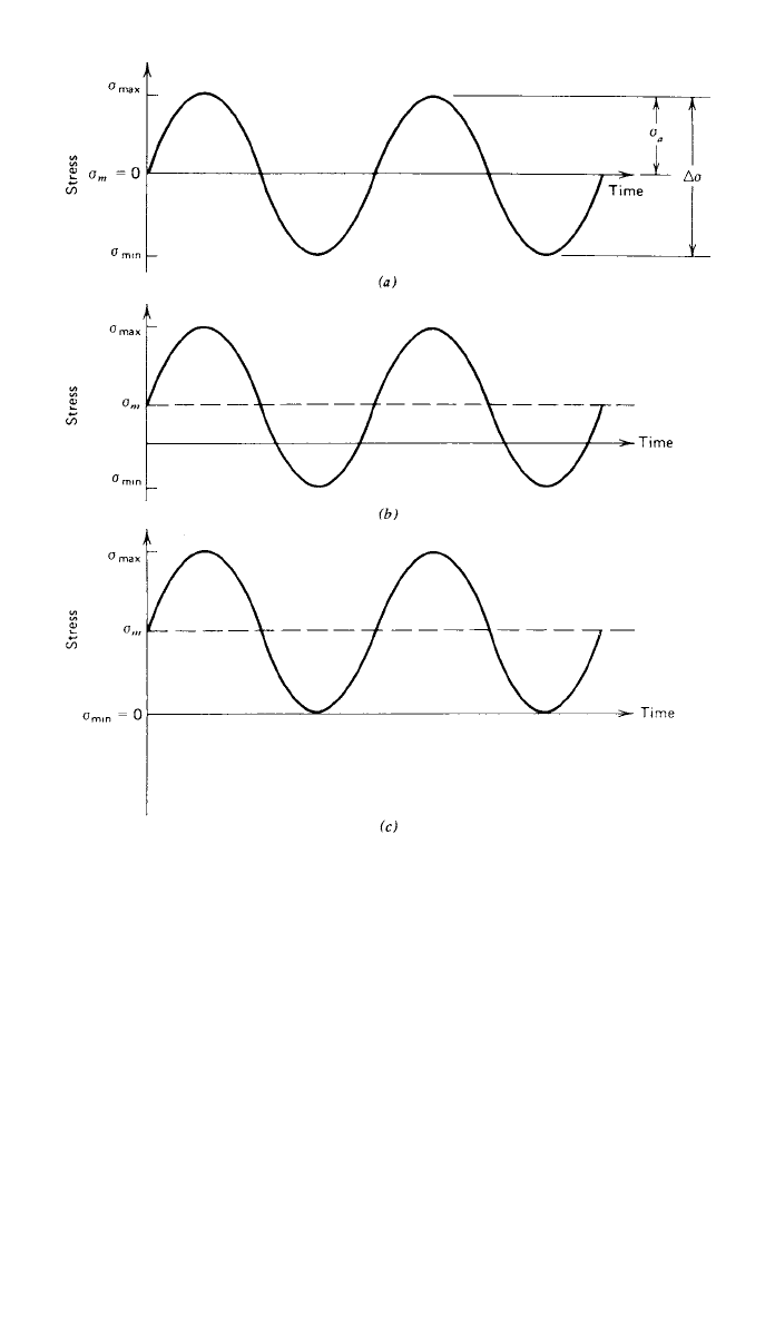
Perhaps the simplest fatigue stress spectrum to which an element may be
subjected is a zero-mean sinusoidal stress–time pattern of constant amplitude
and fixed frequency, applied for a specified number of cycles. Such a stress–
time pattern, often referred to as a completely reversed cyclic stress, is illustrated
in Fig. 7a. Utilizing the sketch of Fig. 7b, we can conveniently define several
useful terms and symbols; these include:
724 FAILURE MODES
Fig. 7 Several constant-amplitude stress –time patterns of interest: (a) completely reversed,
R ⫽⫺1, (b) nonzero mean stress, (c) released tension, R ⫽ 0.
⫽ maximum stress in the cycle
max
⫽ mean stress ⫽ (
⫹
)/2
m max min
⫽ minimum stress in the cycle
min
⫽ alternating stress amplitude ⫽ (
⫺
)/2
a max min
⌬
⫽ range of stress ⫽
⫺
max min
R ⫽ stress ratio ⫽
/
min max
Any two of the quantities just defined, except the combinations
a
and ⌬
, are
sufficient to describe completely the stress–time pattern.
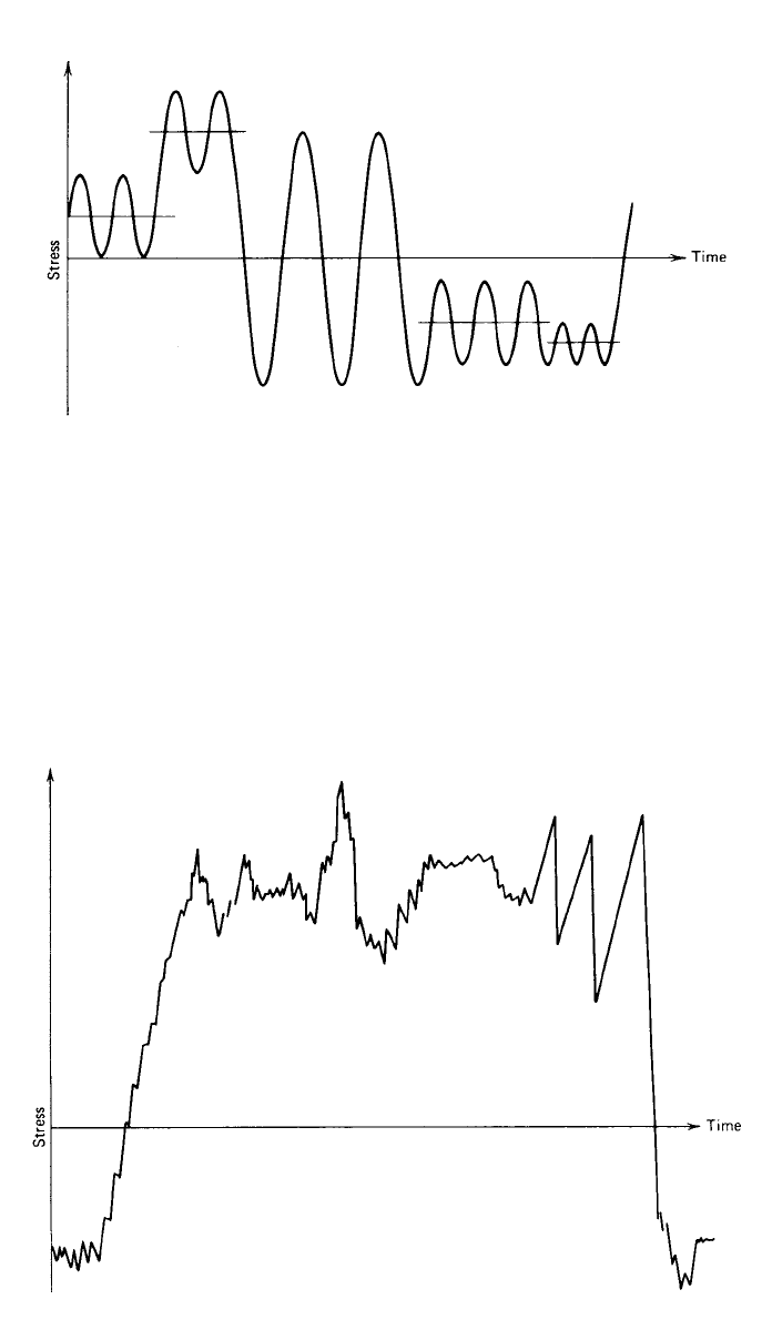
More complicated stress–time patterns are produced when the mean stress,
the stress amplitude, or both change during the operational cycle, as illustrated
in Fig. 8. It may be noted that this stress–time spectrum is beginning to approach
5 FATIGUE 725
Fig. 8 Stress–time pattern in which both mean and amplitude change to produce a more com-
plicated stress spectrum.
Fig. 9 A quasi-random stress–time pattern typical of an aircraft during a given mission.
a degree of realism. Finally, in Fig.9asketch of a realistic stress spectrum is
given. This type of quasi-random stress–time pattern might be encountered in
an airframe structural member during a typical mission including refueling, taxi,
takeoff, gusts, maneuvers, and landing. The obtaining of useful, realistic data is
a challenging task in itself. Instrumentation of existing machines, such as op-
erational aircraft, provide some useful information to the designer if his or her
mission is similar to the one performed by the instrumented machine. Recorded

726 FAILURE MODES
data from accelerometers, strain gauges, and other transducers may in any event
provide a basis from which a statistical representation can be developed and
extrapolated to future needs if the fatigue processes are understood.
Basic data for evaluating the response of materials, parts, or structures are
obtained from carefully controlled laboratory tests. Various types of testing ma-
chines and systems commonly used include:
1. Rotating-bending machines
a. Constant bending moment type
b. Cantilever bending type
2. Reciprocating-bending machines
3. Axial direct-stress machines
a. Brute-force type
b. Resonant type
4. Vibrating shaker machines
a. Mechanical type
b. Electromagnetic type
5. Repeated torsion machines
6. Multiaxial stress machines
7. Computer-controlled closed-loop machines
8. Component testing machines for special applications
9. Full-scale or prototype fatigue testing systems
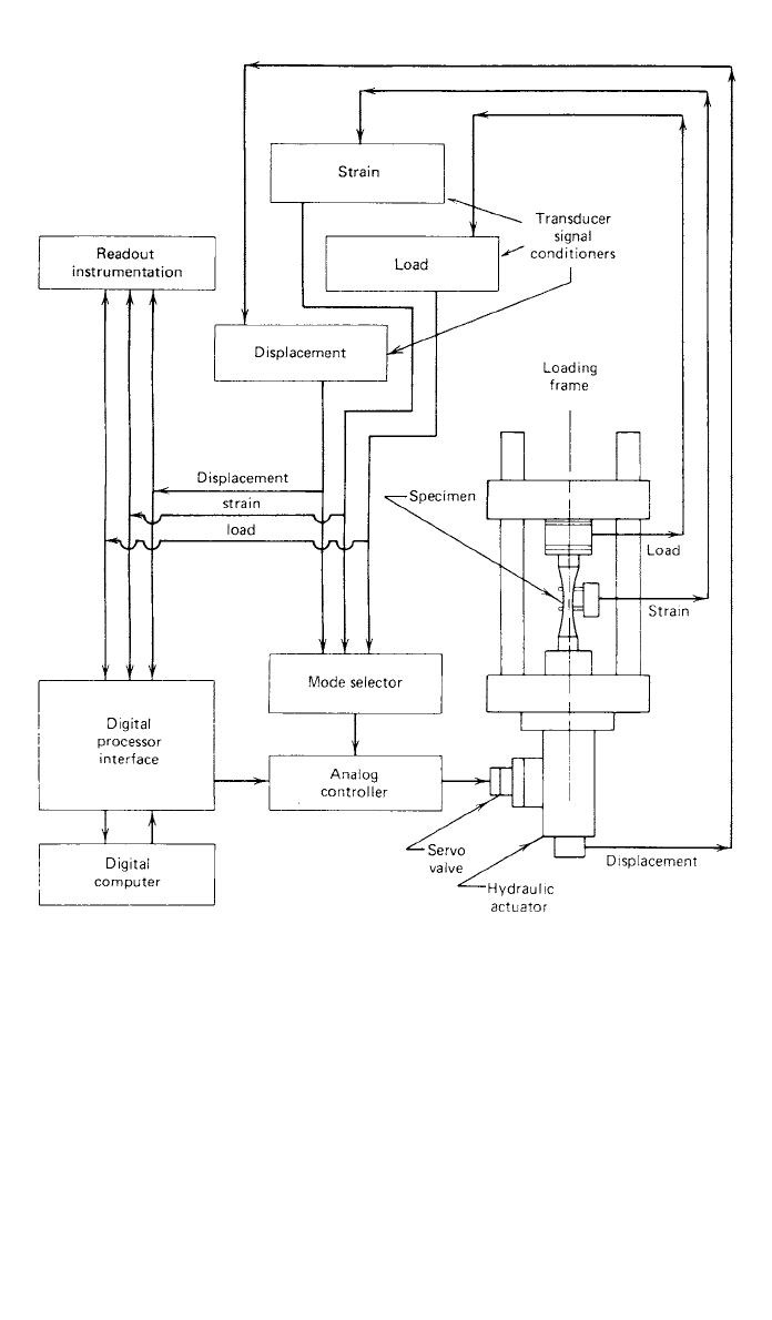
Computer-controlled fatigue testing machines are widely used in all modern
fatigue testing laboratories. Usually such machines take the form of precisely
controlled hydraulic systems with feedback to electronic controlling devices
capable of producing and controlling virtually any strain–time, load–time, or
displacement–time pattern desired. A schematic diagram of such a system is
shown in Fig. 10.
Special testing machines for component testing and full-scale prototype test-
ing are not found in the general fatigue testing laboratory. These systems are
built up especially to suit a particular need, for example, to perform a full-scale
fatigue test of a commercial jet aircraft.
It may be observed that fatigue testing machines range from very simple to
very complex. The very complex testing systems, used, for example, to test a
full-scale prototype, produce very specialized data applicable only to the partic-
ular prototype and test conditions used; thus, for the particular prototype and
test conditions the results are very accurate, but extrapolation to other test con-
ditions and other pieces of hardware is difficult, if not impossible. On the other
hand, simple smooth-specimen laboratory fatigue data are very general and can
be utilized in designing virtually any piece of hardware made of the specimen
material. However, to use such data in practice requires a quantitative knowledge
of many pertinent differences between the laboratory and the application, in-
cluding the effects of nonzero mean stress, varying stress amplitude, environ-
ment, size, temperature, surface finish, residual stress pattern, and others. Fatigue
5 FATIGUE 727
Fig. 10 Schematic diagram of a computer-controlled closed-loop fatigue testing machine.
testing is performed at the extremely simple level of smooth-specimen testing,
the extremely complex level of full-scale prototype testing, and everywhere in
the spectrum between. Valid arguments can be made for testing at all levels.
5.2 S–N–P Curves: A Basic Design Tool
Basic fatigue data in the high-cycle life range can be conveniently displayed on
a plot of cyclic stress level versus the logarithm of life, or alternatively, on a
log-log plot of stress versus life. These plots, called S–N curves, constitute de-
sign information of fundamental importance for machine parts subjected to re-
peated loading. Because of the scatter of fatigue life data at any given stress
level, it must be recognized that there is not only one S–N curve for a given
material, but a family of S–N curves with probability of failure as the parameter.
728 FAILURE MODES
Fig. 11 Family of S–N–P curves or R–S–N curves, for 7075-T6 aluminum alloy.
Note: P ⫽ probability of failure; R ⫽ reliability ⫽ 1–P. (Adapted from Ref. 17, with permission
from John Wiley & Sons, Inc.)
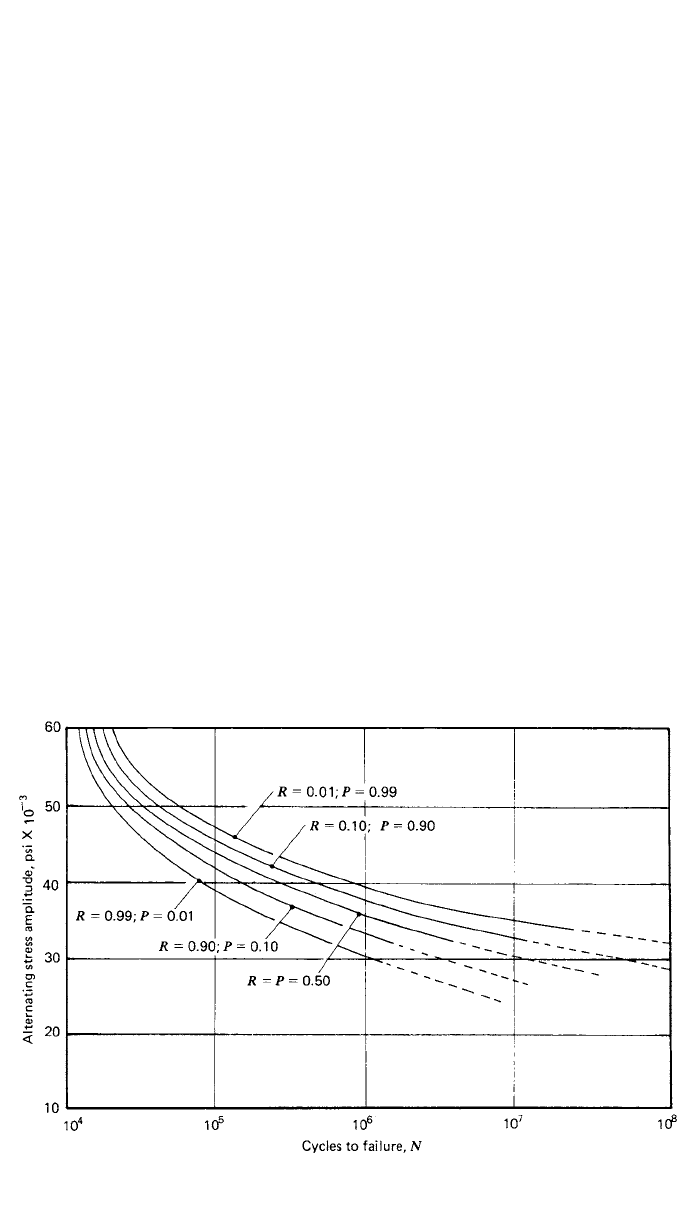
These curves are called the S–N–P curves, or curves of constant probability of
failure on a stress-versus-life plot. A representative family of S–N–P curves is
illustrated in Fig. 11. It should also be noted that references to the ‘‘S–N curve’’
in the literature generally refer to the mean curve unless otherwise specified.
Details regarding fatigue testing and the experimental generation of S–N–P
curves may be found in Ref. 1.
The mean S–N curves sketched in Fig. 12 distinguish two types of material
response to cyclic loading commonly observed. The ferrous alloys and titanium
exhibit a steep branch in the relatively short life range, leveling off to approach
a stress asymptote at longer lives. This stress asymptote is called the fatigue
limit or endurance limit and is the stress level below which an infinite number
of cycles can be sustained without failure. The nonferrous alloys do not exhibit
an asymptote, and the curve of stress versus life continues to drop off indefi-
nitely. For such alloys there is no fatigue limit, and failure as a result of cyclic
load is only a matter of applying enough cycles. All materials, however, exhibit
a relatively flat curve in the long-life range.
To characterize the failure response of nonferrous materials, and of ferrous
alloys in the finite-life range, the term fatigue strength at a specified life,
N
, is
used. The term fatigue strength identifies the stress level at which failure will
occur at the specified life. The specification of fatigue strength without speci-
fying the corresponding life is meaningless. The specification of a fatigue limit
always implies infinite life.
5.3 Factors That Affect S–N–P Curves
There are many factors that may influence the fatigue failure response of ma-
chine parts or laboratory specimens, including material composition, grain size
