Kutz M. Handbook of materials selection
Подождите немного. Документ загружается.

5 FATIGUE 729
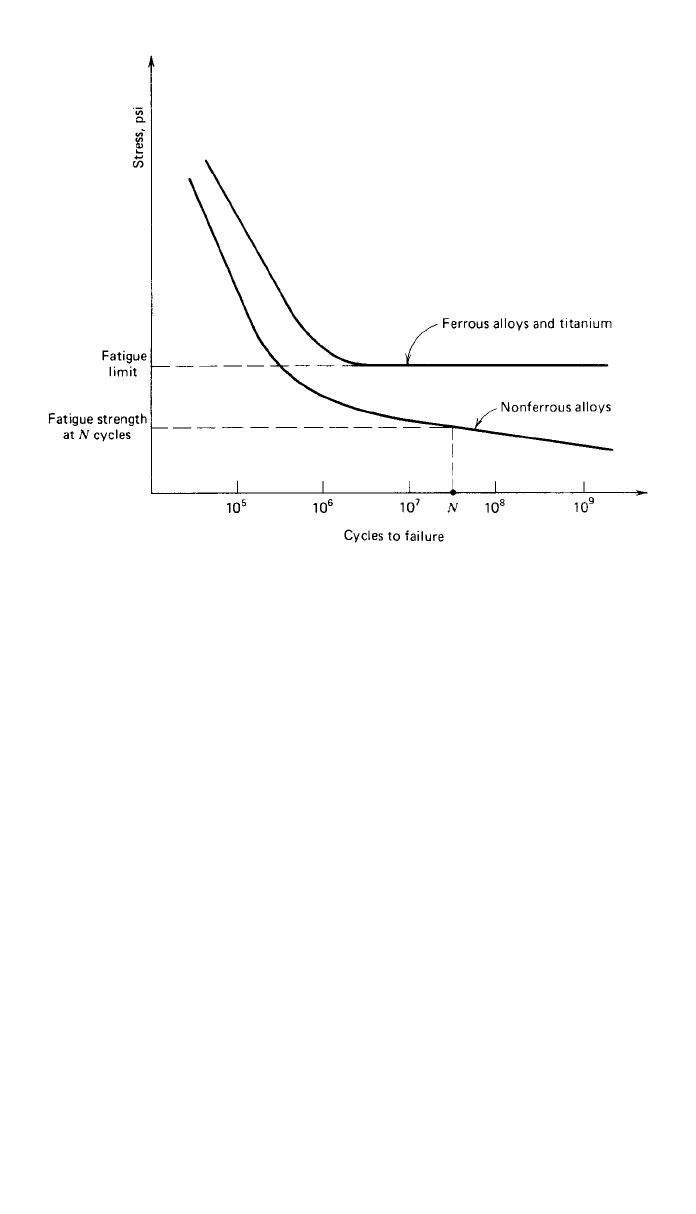
Fig. 12 Two types of material response to cyclic loading.
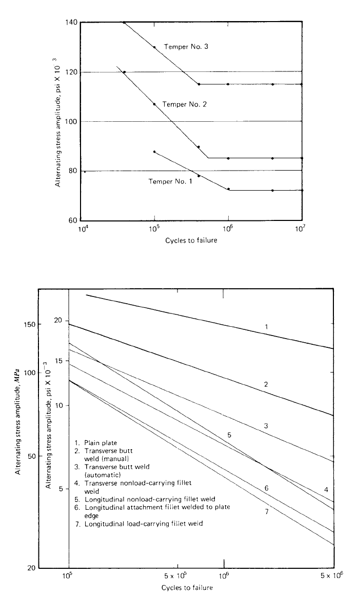
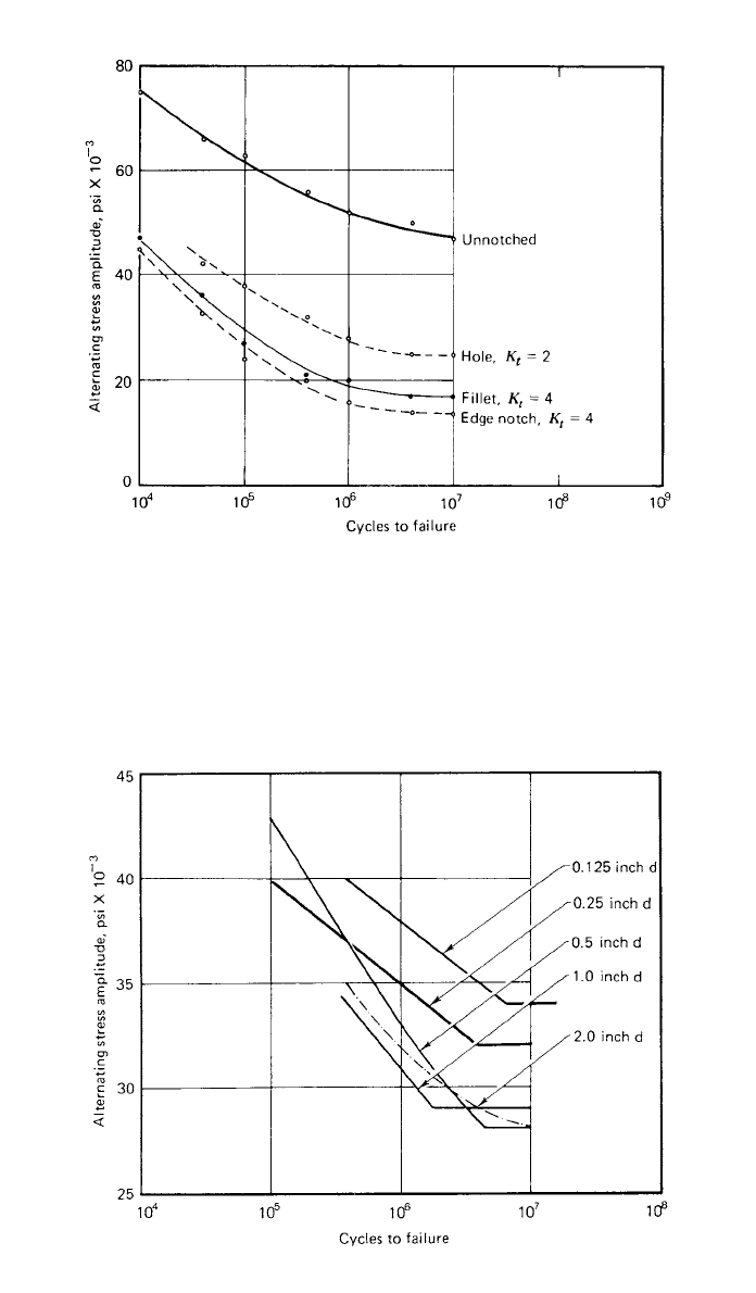
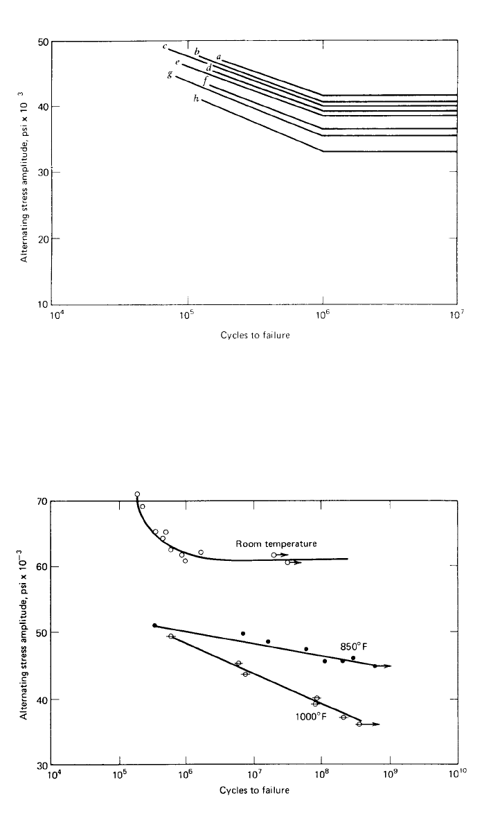
and grain direction, heat treatment, welding, geometrical discontinuities, size
effects, surface conditions, residual surface stresses, operating temperature, cor-
rosion, fretting, operating speed, configuration of the stress–time pattern, non-
zero mean stress, and prior fatigue damage. Typical examples of how some of
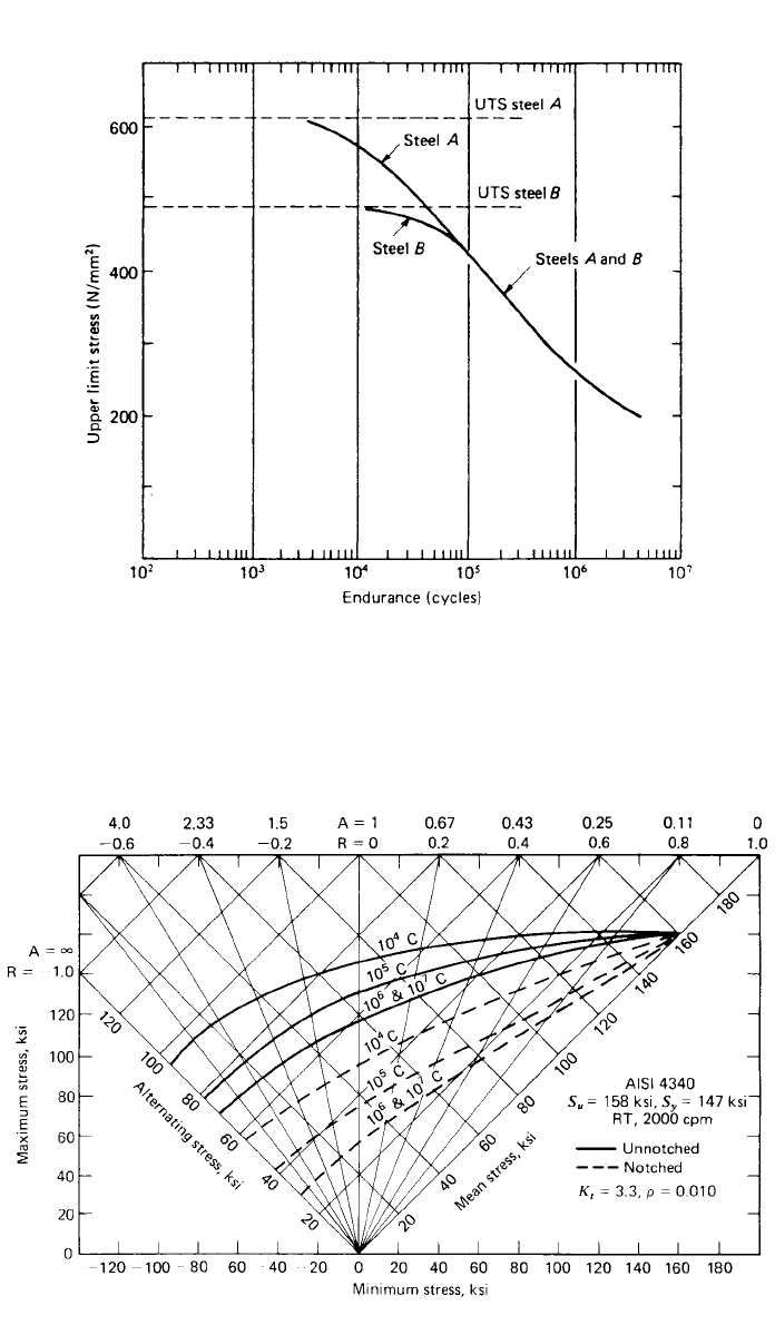
these factors may influence fatigue response are shown in Figs. 13 through 19.
It is usually necessary to search the literature and existing databases to find the
information required for a specific application, and it may be necessary to un-
dertake experimental testing programs to produce data where they are unavail-
able.
5.4 Nonzero Mean Stress
Most basic fatigue data collected in the laboratory are for completely reversed
alternating stresses, that is, zero mean cyclic stresses. Most service applications
involve nonzero mean cyclic stresses. It is therefore very important to a designer
to know the influence of mean stress on fatigue behavior so that he or she can
utilize basic completely reversed laboratory data in designing machine parts
subjected to nonzero mean cyclic stresses.
If a designer is fortunate enough to find test data for his or her proposed
material under the mean stress conditions and design life of interest, the designer
should, of course, use these data. Such data are typically presented on so-called
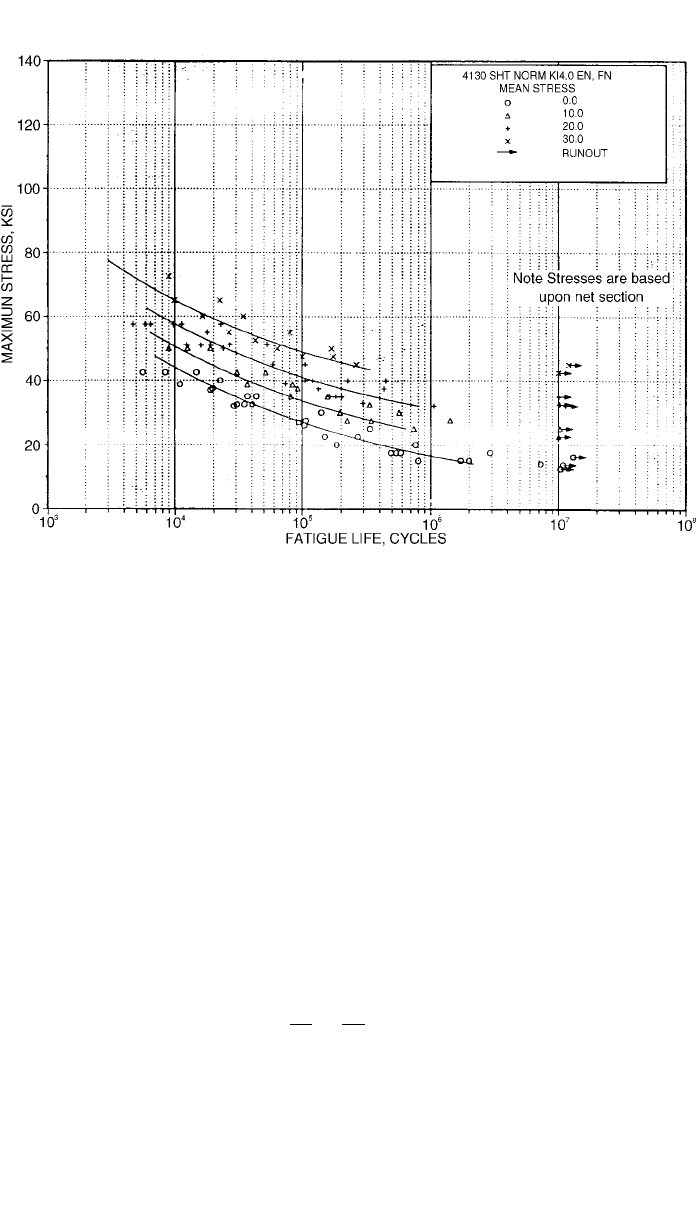
master diagrams or constant life diagrams for the material. A master diagram
for a 4340 steel alloy is shown in Fig. 20. An alternative means of presenting
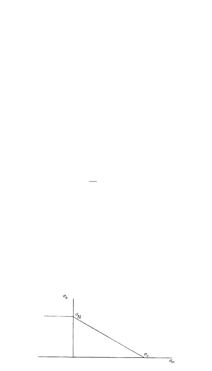
this type of fatigue data is illustrated in Fig. 21 for a 4130 steel alloy.
If data are not available to the designer, he or she may estimate the influence
of nonzero mean stress by any one of several empirical relationships that relate
730 FAILURE MODES
Fig. 13 Effects of heat treatment on the S–N curve of oil quenched SAE 4130 steel.
Temper No. 1: S
u
⫽ 129 ksi; temper No. 2: S
u
⫽ 150 ksi; temper No. 3: S
u
⫽ 206 ksi.
Fig. 14 Effects of welding detail on the S–N curve of structural steel, with yield strength in the
range of 30 –52 ksi. Tests were released tension (R ⫽ 0). (Data from Ref. 18.)
5 FATIGUE 731
Fig. 15 Effects of geometrical discontinuities on the S–N curve of
SAE 4130 steel sheet, tested under completely reversed axial loading.
Specimen dimensions (t ⫽ thickness, w ⫽ width, r ⫽ notch radius);
unnotched: t ⫽ 0.075 in., w ⫽ 1.5 in.; hole: t ⫽ 0.075 in., w ⫽ 4.5 in., r ⫽ 1.5 in.;
fillet: t ⫽ 0.075 in., w
net
⫽ 1.5 in., w
gross
⫽ 2.25 in., r ⫽ 0.0195 in.;
edge notch: t ⫽ 0.075 in., w
net
⫽ 1.5 in., w
gross
⫽ 2.25 in., r ⫽ 0.057 in.
(Data from Ref. 19.)
Fig. 16 Size effects on the S–N curve of SAE 1020 steel specimens cut from
a 3.5-in. diameter hot-rolled bar, testing in rotating bending. (Data from Ref. 20.)
732 FAILURE MODES
Fig. 17 Effect of surface finish on the S–N curve of carbon steel specimens, testing in rotating
bending: (a) high polish, longitudinal direction; (b) FF emery finish; (c) No. 1 emery finish;
(d ) coarse emery finish; (e) smooth file; ( f ) as-turned; (g) bastard file; (h) coarse file.
(Data from Ref. 21.)
Fig. 18 Effect of operating temperature on the S–N curve of a 12% chromium steel alloy.
(Data from Ref. 22)
5 FATIGUE 733
Fig. 19 Effect of ultimate strength on the S–N curve for transverse butt welds in two steels.
(Data from Ref. 23.)
Fig. 20 Master diagram for 4340 steel. (From Ref. 24, p. 37.)
734 FAILURE MODES
Fig. 21 Best-fit S–N curves for notched 4130 alloy steel sheet, K
t
⫽ 4.0. (From Ref. 10.)
failure at a given life under nonzero mean conditions to failure at the same life
under zero mean cyclic stresses. Historically, the plot of alternating stress am-
plitude
a
versus mean stress
m
has been the object of numerous empirical
curve-fitting attempts. The more successful attempts have resulted in four dif-
ferent relationships:
1. Goodman’s linear relationship
2. Gerber’s parabolic relationship
3. Soderberg’s linear relationship
4. The elliptic relationship
A modified form of the Goodman relationship is recommended for general
use under conditions of high-cycle fatigue. For tensile mean stress (
m
⬎ 0),
this relationship may be written
am
⫹⫽1 (13)
Nu
where
u
is the material ultimate strength and
N
is the zero mean stress fatigue
strength for a given number of cycles N. For a given alternating stress, com-
pressive mean stresses (
m
⬍ 0) have been empirically observed to increase
fatigue resistance. However, for conservatism, it is typically assumed that com-
pressive mean stress exerts no influence on fatigue life. Thus, for
m
⬍ 0, the
fatigue response is identical to that for
m
⫽ 0 with
a
⫽
N
.
5 FATIGUE 735
Fig. 22 Modified Goodman relationship.
The modified Goodman relationship is illustrated in Fig. 22. This curve is a
failure locus for the case of uniaxial fatigue stressing. Any cyclic loading that
produces an alternating stress and mean stress that exceeds the bounds of the
locus will cause failure in fewer than N cycles. Any alternating stress–mean
stress combination that lies within the locus will result in more than N cycles
without failure. Combinations on the locus produce failure in N cycles. The
modified Goodman relationship shown in Fig. 22 considers fatigue failure ex-
clusively. The reader is cautioned to ensure that the maximum and minimum
stresses produced by the cyclic loading do not exceed the material yield strength
yp
such that failure by yielding would be predicted to occur.
5.5 Fatigue Crack Propagation
A fatigue crack that has been initiated by cyclic loading, or any other preexisting
flaw in the structure or material, may be expected to grow under sustained cyclic
loading until it reaches the critical size from which it will propagate rapidly to
catastrophic failure in accordance with the principles of fracture mechanics. For
many structures or machine elements, the time required for a fatigue-initiated
crack or a preexisting flaw to grow to critical size is a significant portion of the
total life.
The fatigue crack growth rate da/dN has been found to often correlate with
the crack-tip stress intensity factor range such that
da
⫽ g(⌬K) (14)
dN
where
⌬K is the mode I stress intensity factor range, computed using the max-
imum and minimum applied stresses with
⌬K ⫽ K
max
⫺ K
min
. Most crack growth
rate data produced have been characterized in terms of
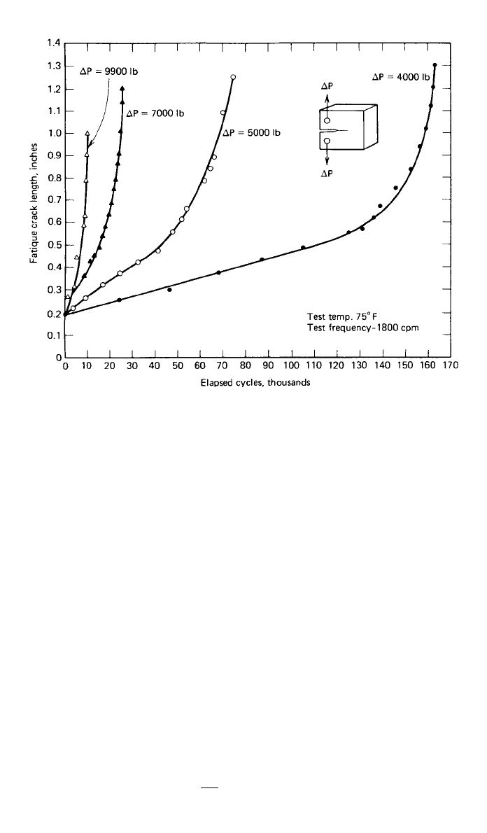
⌬K. For example, Fig.
23 illustrates indirectly the dependence of fatigue crack growth on stress inten-
sity factor. The crack growth rate, indicated by the slope of the a versus N
curves, increases with both the applied load and crack length. Since the crack-
tip stress intensity factor range also increases with applied load and crack length,
it is clear that the crack growth rate is related to the applied stress intensity
factor range.
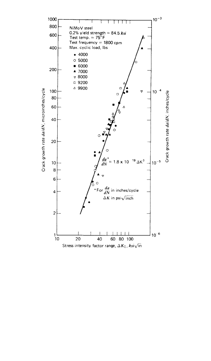
To plot the data of Fig. 23 in terms of the stress intensity factor range and
crack growth rate, the crack growth rate is estimated from a numerically deter-
736 FAILURE MODES
Fig. 23 Effect of cyclic-load range on crack growth in Ni–Mo–V alloy steel for released tension
loading. (From Ref. 37. Reprinted with permission of the Society for Experimental Mechanics,
www.sem.org.)
mined slope of the a versus N curves between successive data points. Corre-
sponding values of
⌬K are then computed from the applied load range and mean
crack length for each interval. The results of this procedure are shown in Fig.
24 for the data presented in Fig. 23. It should be noted that all the curves of
Fig. 23 are incorporated into the single curve shown in Fig. 24 through use of
the stress intensity factor, and the curve of Fig. 24 is therefore applicable to
any combination of cyclic stress range and crack length for released loading
(R
⫽ 0) on specimens of this geometry. Different geometries under different
applied stresses will exhibit identical crack-tip stress fields if the stress intensity
factors are equal. Thus, because the stress intensity factor characterizes the state
of stress near the crack tip, the fatigue crack growth rate correlation shown in
Fig. 24 is applicable to any cyclically loaded component with R
⫽ 0 manufac-
tured using the same material. This allows crack growth data generated from
simple laboratory specimens to be utilized for approximate crack growth pre-
dictions in more complex geometries.
Fatigue crack growth rate data similar to that shown in Fig. 24 have been
reported for a wide variety of engineering metals. The linear behavior observed
using log-log coordinates suggests that Eq. (14) may be generalized as follows:
da
n
⫽ C(⌬K) (15)
dN
where n is the slope of the log da/dN versus log
⌬K plot and C is the da/dN
5 FATIGUE 737
Fig. 24 Crack growth rate as a function of stress–intensity range for Ni–Mo–V steel. (From
Ref. 37. Reprinted with permission of the Society for Experimental Mechanics, www.sem.org.)
value found by extending the straight line to a ⌬K value of unity. This relation-
ship was first proposed by Paris.
27
The empirical parameters C and n are a
function of material, R ratio, thickness, temperature, environment, and loading
frequency. Standard methods have been established for conducting fatigue crack
growth tests,
25
and fatigue crack growth rate data may be found in Ref. 9, 10,
and 12–15. Many other fracture mechanics-based empirical correlations other
than Eq. (15) have been proposed, some of which are discussed by Schijve.
26
An extensive overview of the fatigue crack propagation problem is provided by
Pook.
32
Given an initial crack of length a
i
, Eq. (15) may be integrated to give the
number of cycles N required to propagate a crack to a size a
N
such that
738 FAILURE MODES
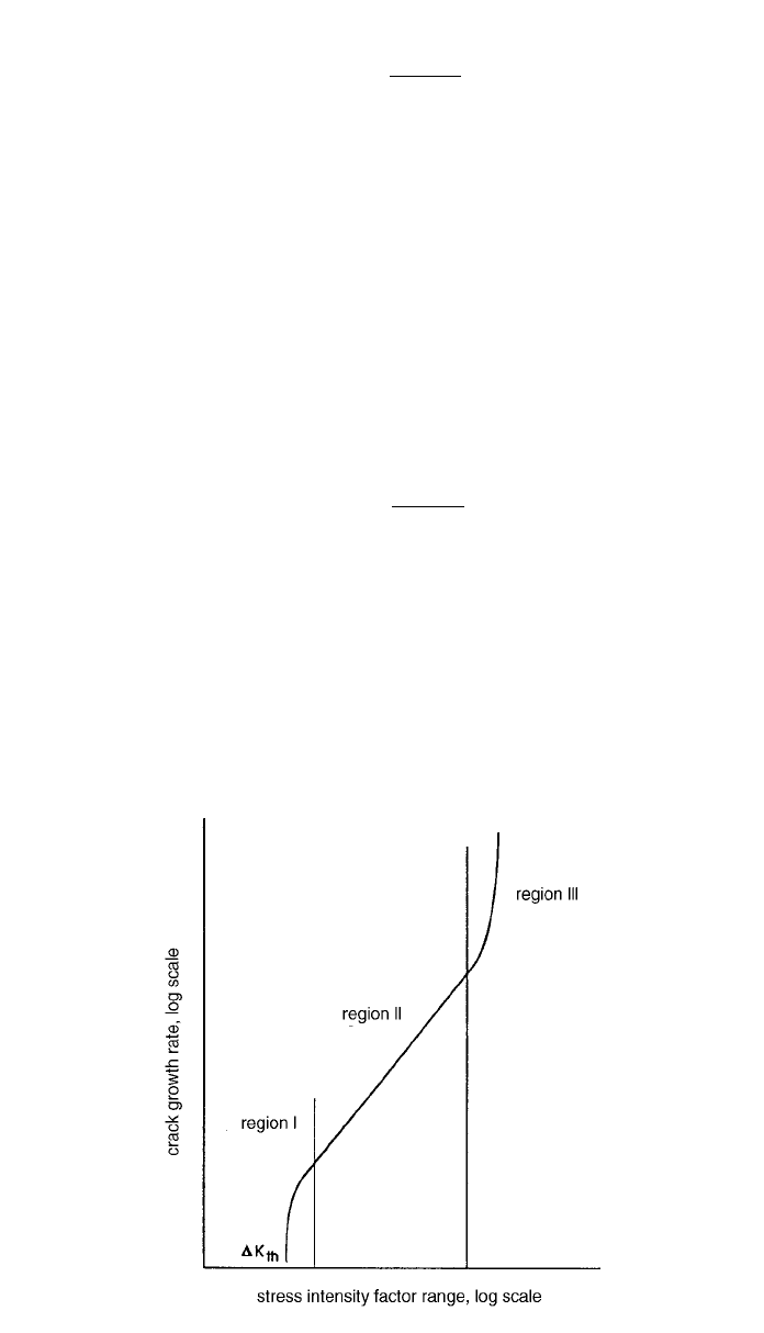
Fig. 25 Schematic representation of fatigue crack growth rate data.
a
N
da
N ⫽ 冕 (16)
n
a
C(⌬K)
i
Given that ⌬K is a function of crack length a, numerical integration techniques
will in general be required to compute N. An approximate procedure and several
idealized examples are presented by Parker.
35
It must be emphasized that Eqs. (15) and (16) are applicable only to region
II crack growth, as illustrated in Fig. 25. Region I of Fig. 25 exhibits a threshold
⌬K
th
below which the crack will not propagate. Region III corresponds to the
transition into the unstable regime of rapid crack extension. In this region, crack
growth rates are large and the number of cycles associated with growth in this
region small.
With an initial crack of length a
i
, from Eq. (16), the number of cycles required
to grow a crack to a critical length a
c
such that rapid crack extension would be
predicted may be approximated as
a
c
da
N ⫽ 冕 (17)
p
n
a
C(⌬K)
i
Assuming an initial crack that has been initiated by cyclic loading, the crack
propagation life N
p
given by Eq. (17) may then be added to the crack initiation
life N
i
to obtain an estimate of the total fatigue life N with
N
⫽ N ⫹ N (18)
ip
Such estimates are highly sensitive to the length of the initial crack a
i
. While
