Kuppan T. Heat Exchanger Design Handbook
Подождите немного. Документ загружается.

694
Chapter
I3
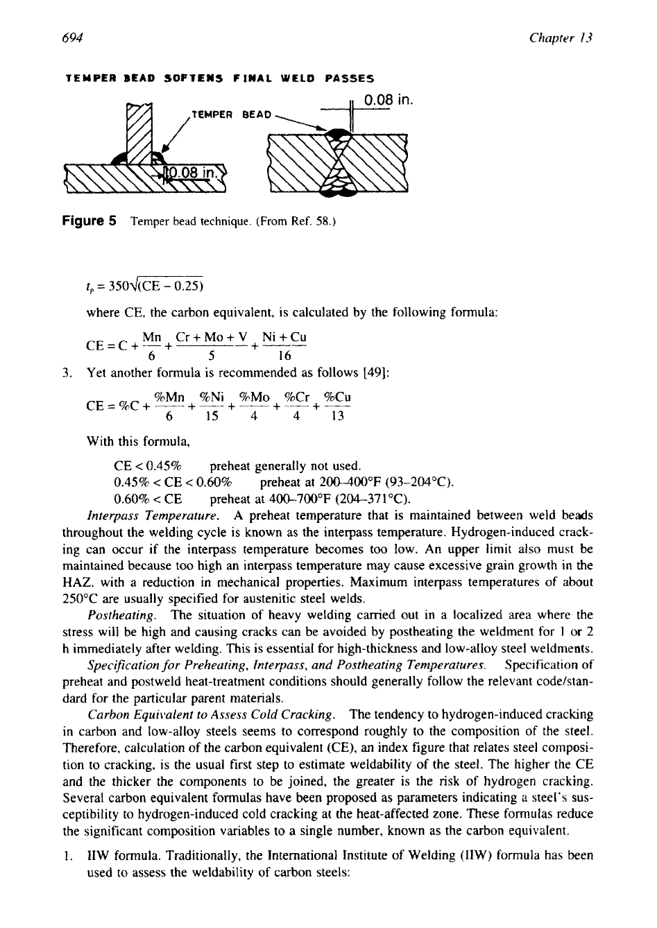
TEMPER
BEAD
SOFTENS
FINAL
WELD
PASSES
Figure
5
Temper
bead
technique. (From
Ref.
58.)
where
CE,
the carbon equivalent, is calculated by the following formula:
Mn Cr+Mo+V+Ni+Cu
CE=C+-+
___-
6
5
16
3.
Yet another formula is recommended as follows
1491:
%Ni %MO %Cr
%Cu
CE
=
%C
+
%Mn
+-+---
+--+-
~
6
15
4 4
13
With this formula,
CE
<
0.45%
preheat generally not used.
0.45%
<
CE
<
0.60%
preheat at
200-400"F (93-204°C).
0.60%
<
CE
preheat at
400-700°F
(204371°C).
Interpass Temperature.
A
preheat temperature that is maintained between weld beads
throughout the welding cycle is known as the interpass temperature. Hydrogen-induced crack-
ing can occur if the interpass temperature becomes too low. An upper limit also must be
maintained because too high an interpass temperature may cause excessive grain growth
in
the
HAZ,
with a reduction in mechanical properties. Maximum interpass temperatures of about
250°C
are usually specified for austenitic steel welds.
Postheating.
The situation of heavy welding carried out in a localized area where the
stress will be high and causing cracks can be avoided by postheating the weldment for
1
or
2
h
immediately after welding. This is essential for high-thickness and low-alloy steel weldments.
Specifcation
for
Preheating, Interpass, and Postheating Temperatures.
Specification of
preheat and postweld heat-treatment conditions should generally follow the relevant codelstan-
dard for the particular parent materials.
Carbon Equivalent
to
Assess
Cold Cracking.
The tendency to hydrogen-induced cracking
in carbon and low-alloy steels seems to correspond roughly to the composition of the steel.
Therefore, calculation of the carbon equivalent
(CE),
an
index figure that relates steel composi-
tion to cracking, is the usual first step to estimate weldability of the steel. The higher the
CE
and the thicker the components to be joined, the greater is the risk of hydrogen cracking.
Several carbon equivalent formulas have been proposed as parameters indicating a steel's sus-
ceptibility to hydrogen-induced cold cracking at the heat-affected zone. These formulas reduce
the significant composition variables to a single number, known as the carbon equivalent.
1.
IIW
formula. Traditionally, the International Institute of Welding (IIW) formula has been
used to assess the weldability of carbon steels:
695
Material Selection
and
Fabrication
Mn Cr+Mo+V
CE(1IW)
=
C
+
-
+
Cu+Ni
+
~
6
15
5
Values of CE(I1W) below
0.42
denote a steel that is easy to weld without cracking; values
above
0.5
are difficult. It is reported that CE(1IW)
is
a more appropriate parameter for
evaluating the cold-working susceptibility of steels whose carbon content is more than
0.16%.
A
more accurate estimate will be obtained if the factor of Si/6 is added to the
CE(1IW) formula
[59]:
CE=C+-+-
Mn+Si Cu+Ni
+
Cr+Mo+V
6
15
15
Low-carbon steels. There is a general feeling that the
IIW
formula is not adequate to
define the behavior of modern steels with low carbon contents
(0.07
to 0.22% C), and the
following relationship by Ito and Bessoy is sometimes preferred
1491:
Si Ni
MO
+-
V
+
5B
P,,
=
CE
=
C
+
-
+
-
+
Mn+Cu+Cr
+--
30
60
20
15 10
CE
is in the range
0.35
to
0.45
depending on the plate thickness, and restraint is susceptible
to cold cracking.
Pc,
has been shown to be reliable for evaluating the cold-cracking ten-
dency in low-carbon steels.
Yurioka et al. formula
[60].
This is a general-purpose formula. Due to the reason given in
item 2, it is not possible for one simple carbon equivalent formula to describe, overall, the
cold-working tendency of steels if their carbon contents range widely
[60].
It is with this
in mind that Yorioka et al. proposed the following CE formula, which has an accommoda-
tion factor A (C) as a function of the
CE:
Si Mn Cu Ni
+
Cr+Mo+Nb+V+5B
-
+-+
-+-
24
6
15 20
5
where A(C)
=
0.75
+
0.25 tanh{20(C
-
0.12)).
A(C) increases with an increase in carbon
content. It approaches
0.5
as the carbon content decreases below
0.08%
and 1.0 as it
increase above
0.18%.
As a parameter describing the probability of the occurrence of cold
cracking in steel welding, a cracking index
(CI)
was proposed. It is expressed as
CI
=
CE
+
0.15 log
H,Is
+
0.30 log(0.017
KtOw)
where
HJS
is the hydrogen content in the deposited weld metal determined using
JIS
glycerin displacement method,
(HIIw
-
0.61y1.3;
K,
is the stress concentration factor at
root and toe weld positions where a crack is initiated-K, is 1.5 for V (root),
4
to
5
for Y
(root), and
3.5
for double V (root) (for others refer to Ref.
60);
and
ow
is the mean stress
acting on the weld metal.
Yurioka et al. proposed the necessary preheating temperatures to avoid cold cracking
by
the following criterion:
where
tloo
is the cooling time to 100°C (212°F); this is influenced not only by the preheat-
ing temperature employed, but also by welding heat input, plate thickness and preheating
method. Critical time
(t,(&
is given as

696
Chapter
13
(tloo),,
=
exp(67.6 C13
-
182.0 CI'
+
163.8 CI
-
41.0)
4.
Stout and Doty formula for
CE
[48]:
%Mn %Ni %Cr+%Mo
+-
%Cu
CE= %C
+-+-+
6
20
10
40
If CE is <0.40, the steel may be insensitive to hydrogen cracking; over
0.50,
cracking
is
sure, and low hydrogen welding procedures are necessary.
5.
Hardenable carbon steels and alloy steels. This formula takes into account the silicon
content and equation for CE is given by [56]:
%Mn
+
%Cr
+
%MO
+
%V
%Si
+
%Ni
+
%Cu
CE=%C+-
-+
6
5
15
Using this formula, steels having carbon equivalents
of
less than
0.35%
usually require
no
preheating or postheating. Steels with carbon equivalents between 0.35 and
0.55%
usually
require preheating, and steels with carbon equivalents greater than
0.55%
may require
both
preheating and postheating.
6.
Recently, expressions that include fabrication conditions such as heat input, cooling rate,
joint design, and restraint conditions have also been proposed. This includes:
PH
=
P,,
+
0.075
log,"
H
+
R1/40,000
where
PH
is the cracking susceptibility parameter,
H
is
the concentration of hydrogen
(ppm),
Rf
the restraint stress (MPa), and
P,,
was defined earlier.
Maximum Carbon Equivalent as per ASTM A20.
As per ASTM Specification A20, for
weldability considerations, the plates shall be specified with
a
specific maximum carbon equiv-
alent
(CE)
value based on heat analysis. The CE shall be calculated using the following for-
mula:
Mn Cr+Mo+V Ni+Cu
CE=C+-+
+-------
6
5
15
The maximum values of the carbon equivalent for C-steels, including C-Mn, C-Mn-Si, and
C-
Mn-Si-A1 steels, are given in Table
9.
Caution About Using the Carbon Equivalent Formulas to Predict Preheating Temperature.
Because the carbon equivalent is calculated from the base metal composition and includes
no
other variables related to filler metal and welding procedures, it is only an approximate mea-
sure of weldability or predicting susceptibility to hydrogen-induced cracking.
Table
9
Maximum Carbon Equivalent
of
Plate Steels Conforming to
ASTM A20
for
Weldability
Maximum CE value
Specified minimum
UTS,
ksi (MPa)
Up to 2 in thick
>2
in thick
60
I
UTS
<
70
(4
15
I
UTS
<
485)
0.45
0.46
70
I
UTS
<
80
(485
I
UTS
<
550
0.47
0.48
...
UTS
2
80
(UTS
2
550)
0.48
Note.
For
applicability of
various
conditions, refer
ASTM
Specification
A20.
697
Material Selection and Fabrication
Underbead Cracking
Underbead cracks are cold cracks that are most frequently encountered when welding a harden-
able base metal. This is found at the toes of weld deposits and is promoted by these factors
[56]:
(1)
increased base metal hardenability contributed by high carbon and alloying elements
content;
(2)
depositing small welds
so
that the cooling rates after welding favor the formation
of hard, brittle
HAZ;
(3)
weld designs that impose a high degree of mechanical restraint on
the weld metal; and
(4)
the presence of hydrogen. Underbead cracking can be minimized or
prevented by using low-hydrogen electrodes or by preheating joints to the range of
250400°F
and avoiding the already mentioned facators that cause underbead cracking.
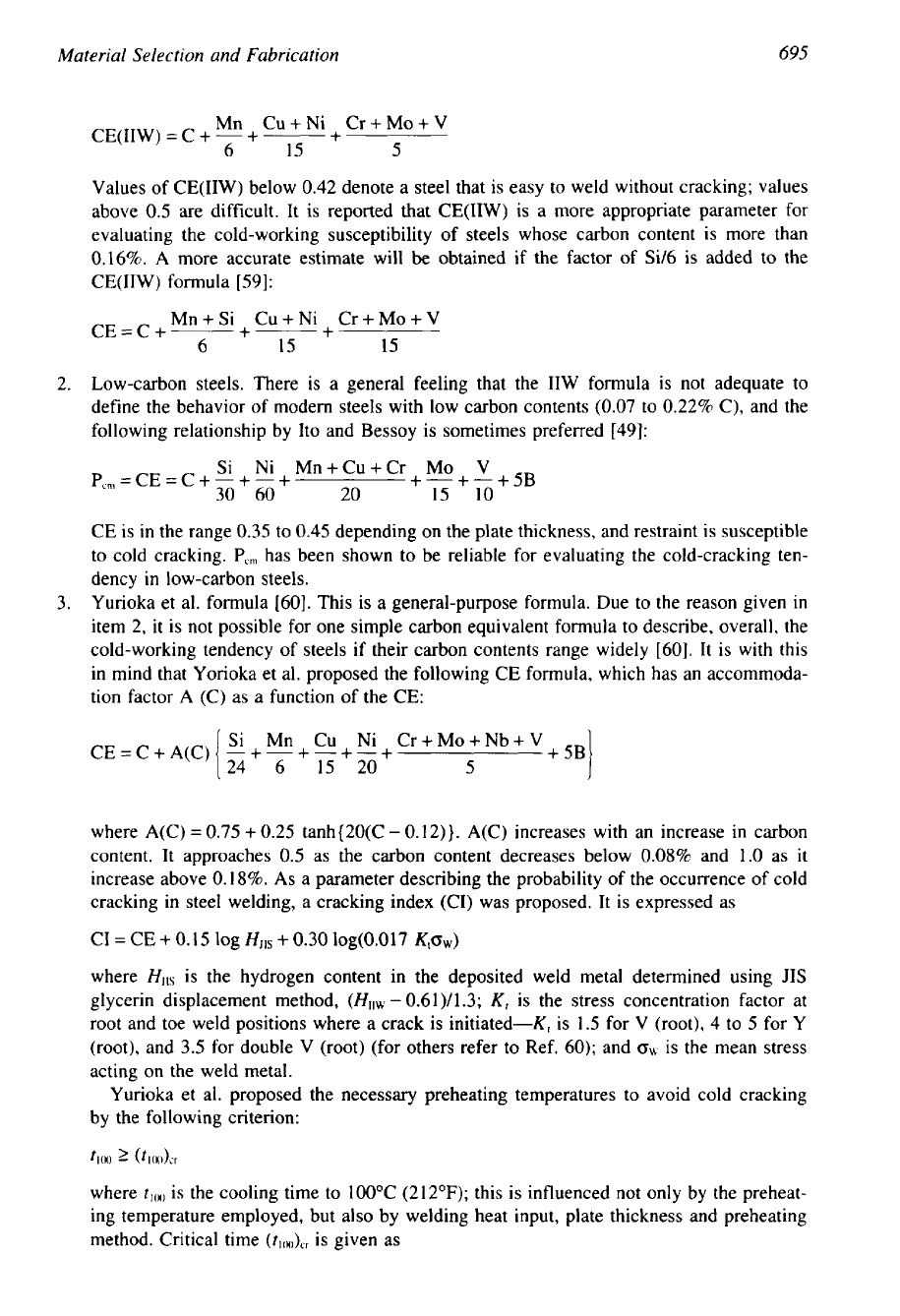
Lamellar Tearing
Lamellar tearing is a cold-cracking phenomenon that occurs beneath welds, and is principally
found in rolled steel plate fabrications. The tearing always lies within the parent plate, often
outside the visible heat-affected zone
(HAZ).
It is characterized by step-like cracking parallel
to the rolling plane [15,56,61,62]. Lamellar tearing is due to the presence of planar inclusions
lying parallel to the plate surface, and it is shown schematically in Fig. 6.
For a given type of welded joint-T (Fig.
7),
L, or cruciform configuration-the occur-
rence of lamellar tearing will be governed by the drop in strength and ductility of a plate in
the through-thickness direction
(z
direction) as compared with the rolling direction. This anisot-
ropy results in particular from the content and shape of the nonmetallic inclusions such as
silicates, sulfides, and alumina, which in turn are influenced by degassing and the rolling
technique. Such conditions usually are present in conventionally melted steels. When the ingot
Figure
6
Lamellar tearing
due
to planar inclusion lying parallel
to
the
surface.
(From
Ref.
63.)
Figure
7
T-Joint susceptible
to
lamellar tearing.

698
Chapter
13
is rolled to form plates, the inclusions deform into platelets with resultant loss in through
thickness direction strength. All conventional steels are susceptible to lamellar tearing to some
extent: mild and low-alloy steels whether semikilled or fully killed and including vacuum-
degassed steels. For a given inclusion content, lamellar tearing is more likely as the strength
of the steel increases.
A
considerable amount of rectification is usually necessary to repair the
defect, and hence this is of considerable concern and trouble to the fabricator should it occur
[63]. Because of this, lamellar tearing has attracted increasing interest from both the steel-
making industry and the fabrication industry.
Conditions That Promote Lamellur Tearing.
For lamellar tearing to occur, these conditions
must be satisfied [56,62]:
Strains must develop in the short transverse direction of the plate. These strains arise from
weld metal shrinkage in the joint but can be greatly increased by strains developed from
reaction with other joints in restrained structures.
The fusion boundary is roughly parallel to the plate surface.
Susceptible base material with a local concentration of inclusions, particularly those ex-
tended in planar directions.
Section thickness: Lamellar tearing does not normally occur in welds of lighter gage plates
because of insufficient constraint. Most reported occurrences of tearing are in plates greater
than
25
mm
in
thickness [62].
Factors affecting weldment cracking due to lamellar tear (subcritical mode) include
[
101
through-thickness ductility, size, shape, and distribution of inclusions, matrix-inclusion cohe-
sion, residual welding strains, mechanical constraints, and temperature.
StructuresLLocations Prone
to
Lamellar Tearing.
Any joint may be subject to lamellar tearing
under certain conditions where a restrained weld is laid against
a
plate surface rather than the
edge. From an analysis of fabrication failures, it appears that three major categories of structure
type are commonly associated with the problem [62]:
1.
Nozzle or penetrator set through a rigid plate (Fig.
8).
2.
Stiffeners or end closure plates in cylindrical structures.
3.
Shell to tubesheet connection on fixed-tubesheet heat exchangers (Fig. 6b).
Prevention
of
Lamellar
Tearing.
The risk of lamellar tearing can be solved by directing
attention toward steel quality, appropriate design, and welding and fabrication techniques.
These approaches are discussed next.
Melting Practice. The
most reliable method of avoiding lamellar tearing involves special
melting and solidification technique. Any steel-making technique that reduces the inclusion
content of the steel will improve the steel properties in the through-thickness direction
(z
direction) and reduce the risk of tearing. Examples are deoxidation practices such as
(1)
low
sulfur content accomplished by ladle addition of cerium or calcium, (2) sulfide shape control,
i.e., to “ball up” the sulfides into spheres that do not spread out into relatively large platelets
during rolling, and (3) use of aluminum or other strong deoxidizers to protect the shape control
and prevent silicate formation and improve through thickness ductility; also,
(4)
slabs may be
continuously cast rather than being rolled from ingots, and
(5)
vacuum melting can reduce
oxygen content and incremental rapid solidification to reduce segregation. These techniques
are described in detail in Refs.
56,
61, and 62 and by Gross et al. 1641.

Mate ria
1
Selection
and
Fabrication
699
Figure
8
(From
Ref.
62.)
Locations in heat exchanger prone
for
lamellar tearing; nozzle
set
through
a
rigid plate.
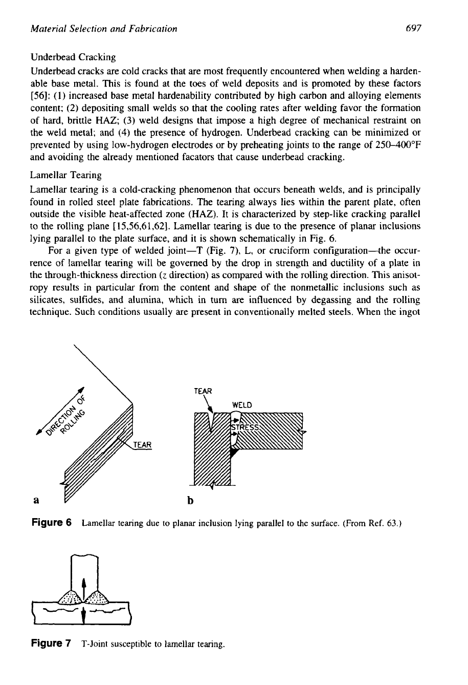
Design Improvements. Many instances of lamellar tearing can be avoided in practice by
improvements in design:
Replacement of crucifonn joints by offset T configurations.
Replacement of
T
or L joints by butt joints.
Location of T joints in regions of lower restraint.
Replacement of plates by forgings, castings, or extrusions in critical T and L joints, or to avoid
fillet welds.
Design improvements to overcome lamellar tearing are shown in Fig. 9a.
Buttering or grooving and buttering, and in situ buttering of the plate surface
[62].
Selection of sequence
of
turns to reduce strains in plates susceptible to lamellar tearing.
Balanced welding.
Control
of
preheating and interpass temperature to minimize tensile strains around the joint.
Following low-hydrogen welding practice.
Shot-peening the weld beads.
Welding Procedural Factors. The following can be helpful measures:
Welding procedures such as buttering and balanced welding are shown in Fig. 9b.
Conventional pulse echo tech-
niques, although useful for detecting laminations in plate, cannot reliably detect small inclu-
sions, which can give rise to lamellar tears
[62].
Hence for further assurance, additional testing
is conducted at room temperature, known as the through-thickness tensile test. In this test, the
strain developed during weld cooling is simulated, and the material parameter associated with
lamellar tearing resistance, through-thickness reduction
of
area (TTRA),
is
easily measured.
A
TTRA
value of
20%
or more is indicative of resistance to lamellar tearing. Steels are processed
so
as to achieve high
TTRA
values and thereby provide high resistance to lamellar tearing.
ASTM
Specification
A770
covers procedures and acceptance standards for through-thickness
tension tests. The room-temperature through-thickness tensile tests specimens of any one of
the following can be used
[65]:
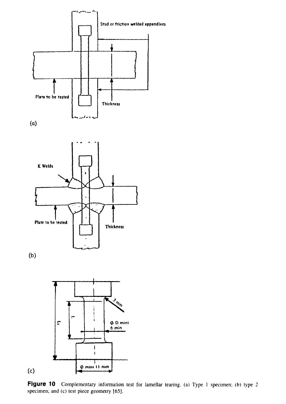
Complentary Information Test for Lamellar Tearing.
Material Selection
and
Fabrication
699
Figure
8
(From
Ref.
62.)
Locations in heat exchanger prone
for
lamellar tearing; nozzle
set
through
a
rigid plate.
Design Improvements. Many instances of lamellar tearing can be avoided in practice by
improvements in design:
Replacement of crucifonn joints by offset T configurations.
Replacement of
T
or L joints by butt joints.
Location of T joints in regions of lower restraint.
Replacement of plates by forgings, castings, or extrusions in critical T and L joints, or to avoid
fillet welds.
Design improvements to overcome lamellar tearing are shown in Fig. 9a.
Welding Procedural Factors. The following can be helpful measures:
Buttering or grooving and buttering, and in situ buttering of the plate surface
[62].
Selection of sequence
of
turns to reduce strains in plates susceptible to lamellar tearing.
Balanced welding.
Control
of
preheating and interpass temperature to minimize tensile strains around the joint.
Following low-hydrogen welding practice.
Shot-peening the weld beads.
Welding procedures such as buttering and balanced welding are shown in Fig. 9b.
Conventional pulse echo tech-
niques, although useful for detecting laminations in plate, cannot reliably detect small inclu-
sions, which can give rise to lamellar tears
[62].
Hence for further assurance, additional testing
is conducted at room temperature, known as the through-thickness tensile test. In this test, the
strain developed during weld cooling is simulated, and the material parameter associated with
lamellar tearing resistance, through-thickness reduction
of
area (TTRA),
is
easily measured.
A
TTRA
value of
20%
or more is indicative of resistance to lamellar tearing. Steels are processed
so
as to achieve high
TTRA
values and thereby provide high resistance to lamellar tearing.
ASTM
Specification
A770
covers procedures and acceptance standards for through-thickness
tension tests. The room-temperature through-thickness tensile tests specimens of any one of
the following can be used
[65]:
Complentary Information Test for Lamellar Tearing.
699
Material Selection
and
Fabrication
Figure
8
Locations in heat exchanger prone
for
lamellar tearing; nozzle
set
through
a
rigid plate.
(From
Ref.
62.)
Design Improvements. Many instances of lamellar tearing can be avoided in practice by
improvements in design:
Replacement of crucifonn joints by offset T configurations.
Replacement of
T
or L joints by butt joints.
Location of T joints in regions of lower restraint.
Replacement of plates by forgings, castings, or extrusions in critical T and L joints, or to avoid
fillet welds.
Design improvements to overcome lamellar tearing are shown in Fig. 9a.
Welding Procedural Factors. The following can be helpful measures:
Buttering or grooving and buttering, and in situ buttering of the plate surface
[62].
Selection of sequence
of
turns to reduce strains in plates susceptible to lamellar tearing.
Balanced welding.
Control
of
preheating and interpass temperature to minimize tensile strains around the joint.
Following low-hydrogen welding practice.
Shot-peening the weld beads.
Welding procedures such as buttering and balanced welding are shown in Fig. 9b.
Complentary Information Test for Lamellar Tearing.
Conventional pulse echo tech-
niques, although useful for detecting laminations in plate, cannot reliably detect small inclu-
sions, which can give rise to lamellar tears
[62].
Hence for further assurance, additional testing
is conducted at room temperature, known as the through-thickness tensile test. In this test, the
strain developed during weld cooling is simulated, and the material parameter associated with
lamellar tearing resistance, through-thickness reduction
of
area (TTRA),
is
easily measured.
A
TTRA
value of
20%
or more is indicative of resistance to lamellar tearing. Steels are processed
so
as to achieve high
TTRA
values and thereby provide high resistance to lamellar tearing.
ASTM
Specification
A770
covers procedures and acceptance standards for through-thickness
tension tests. The room-temperature through-thickness tensile tests specimens of any one of
the following can be used
[65]:
-
----
--
700
Chapter
13
Modification
3
bevel
to
reduce
ris&
Lame
Iiar
tearing
--
Wcring
Grooving and
butter in9
in
situ
buttering
Balanced welding
-_I_
(b)
Figure
9
Methods
to
overcome lamellar tearing.
(a)
T-Joint original design and improvements
and
(b)
welding techniques. (From Ref.
62.)
1. Type 1. These tests are recommended for all thicknesses and fitted with welded extensions.
They may be machined from friction-welded assemblies or stud-welded or fusion-welded
extensions. Friction- or stud-welded extensions are recommended in order to test the plates
as close to the surface as possible. The Type 1 specimen is shown schematically in Fig.
1 Oa.
2.
Type
2.
Test pieces of this type are recommended for plates having a thickness over
25
mm.
The Type
2
specimen is shown schematically in Fig. lob.
Detection
of
Lamellar Tearing
After
Welding.
For surface tears, visual, dye penetrant and
magnetic particle testing will be satisfactory. For subsurface tears, ultrasonics is probably the
most widely used technique, but there may be problems in distinguishing true lamellar tears
from inclusion bands and other forms of cracking. Therefore, pay particular attention to the
position of the cracking in relation to the plate thickness and weld fusion boundary, to avoid
confusion with lack
of
penetration defects, entrapped slags, etc.
[62].
Plate
to
be
tested
Thickness
3
Figure
10
Complementary information test
for
lamellar tearing.
(a)
Type
1
specimen;
(b)
type
2
specimen; and (c) test piece geometry
[65].
702
Chapter
I3
Fish-Eye Cracking
Fish-eye cracking is a form of hydrogen-induced cracking that occurs in weld metal and ap-
pears as small bright spots on the fractured faces of broken specimens
of
weld metal. These
small bright spots are similar to fish eyes, and hence the name fish-eye cracking. The fish-eye
usually surrounds some discontinuity in the metal, such as a hydrogen gas pocket or a nonme-
tallic inclusion, which gives the appearance of a “pupil in an eye.” The conditions that lead
to
fish-eye cracking can be minimized by using dry low-hydrogen electrodes or by heating the
weldments for some period in the temperature range of 200-300°F. Longer times are required
with lower temperatures.
8
HOT
CRACKING
Hot cracking occurs during solidification and cooling
of
a weld,
in
the weld metal or
in
the
heat-affected zone. It occurs above solidus temperature of the lowest melting phase present.
During the final stages
of
solidification, narrow solid bridges separating areas of low melting
liquid are subject
to
the maximum proportion of the shrinkage-induced strains. An increase in
the amount of low-melting phase or the inherent strain resulting from solidification shrinkage
may cause fracture
of
these solid bridges, thus resulting in hot cracks
[66].
Hot cracking is the
subject of most fabrication weldability testing,
so
much
so
that many fabricators equate the
term “weldability” with “hot cracking” and use the terms interchangeably
[48].
8.1
Factors Responsible for Hot Cracking
Most mechanisms proposed deal with the metallurgical factors that can lead to hot cracking.
Hot cracking will occur due to
(1)
segregation of low-melting-point elements,
(2)
sufficient
stress applied to a susceptible microstructure, and
(3)
the mode of solidification.
Segregation of Low-Melting-Point Elements
The segregation
of
low-melting-point elements, such as phosphorus and sulfur, or the presence
of a eutectic can cause hot cracking by extending the temperature range over which liquid is
present
in
the microstructure. By restricting the individual concentrations of sulfur and phos-
phorus, resistance to solidification cracking may be obtained.
Stress States That Induce Restraint
Stresses are invariably present
in
a solidifying weldment due to the complex thermomechanical
transients that occur during welding. Thermal expansion and contraction, plastic strains, phase
transformations involving volumetric changes, etc. contribute to the stress states that induce
restraint
[67].
Mode of Solidification
In
certain cases, as
in
austenitic stainless steel, the mode of solidification, whether as primary
austenite or primary ferrite, strongly influences the sensitivity to hot cracking, presumably due
to the differing distribution of minor elements between these two phases.
8.2
Susceptible
Alloys
These include
(1)
copper-base alloys like silicon bronzes, aluminum bronzes, and copper-
nickels,
(2)
aluminum alloys,
(3)
fully austenitic and superaustenitic stainless steels, and
(4)
nickel-base alloys.
703
Material Selection and Fabrication
8.3
Types of
Hot Cracking
Various types of hot cracking are:
Solidification cracking.
HAZ
liquation cracking, microfissuring.
Reheat cracking.
Ductility dip cracking.
Chevron cracks.
Crater cracks.
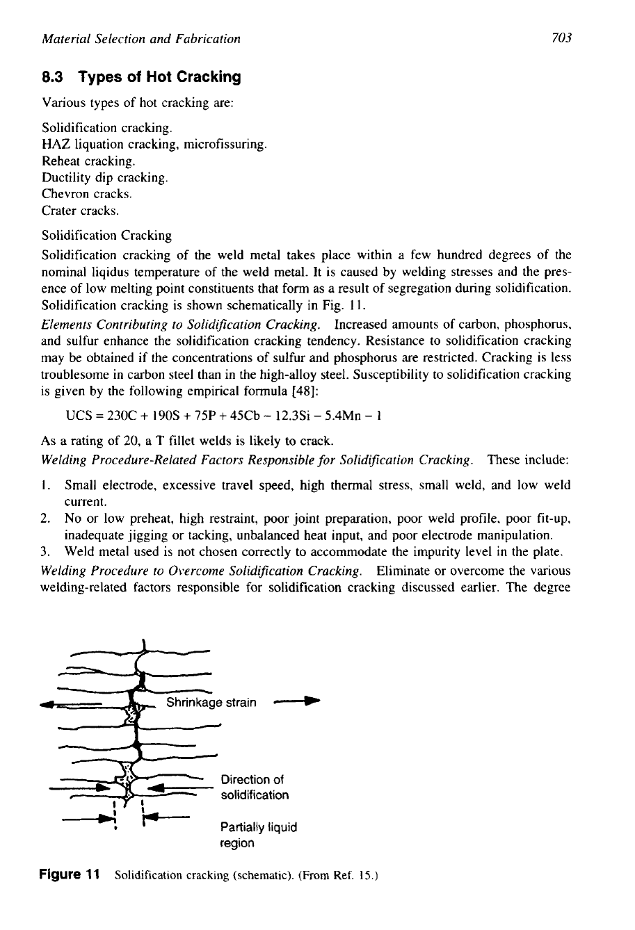
Solidification Cracking
Solidification cracking of the weld metal takes place within a few hundred degrees of the
nominal liqidus temperature of the weld metal. It is caused by welding stresses and the pres-
ence of low melting point constituents that form as a result
of
segregation during solidification.
Solidification cracking is shown schematically in Fig. 1
1.
Elements Contributing to Solidification Cracking.
Increased amounts of carbon, phosphorus,
and sulfur enhance the solidification cracking tendency. Resistance to solidification cracking
may be obtained if the concentrations of sulfur and phosphorus are restricted. Cracking is less
troublesome in carbon steel than in the high-alloy steel. Susceptibility to solidification cracking
is given by the following empirical formula [48]:
UCS
=
230C
+
190s
+
75P
+
45Cb
-
12.3Si
-
5.4Mn
-
1
As
a rating of 20, a T fillet welds is likely
to
crack.
Welding Procedure-Related Factors Responsible
for
Solidification Cracking.
These include:
1.
Small electrode, excessive travel speed, high thermal stress, small weld, and low weld
current.
2.
No
or low preheat, high restraint, poor joint preparation, poor weld profile, poor fit-up,
inadequate jigging or tacking, unbalanced heat input, and poor electrode manipulation.
3.
Weld metal used is not chosen correctly to accommodate the impurity level in the plate.
Welding Procedure to Overcome Solidification Cracking.
Eliminate or overcome the various
welding-related factors responsible for solidification cracking discussed earlier. The degree
Shrinkage strain
4
Direction
of
k.
'-
Partially liquid
region
Figure
11
Solidification cracking (schematic).
(From
Ref.
15.)