Kuppan T. Heat Exchanger Design Handbook
Подождите немного. Документ загружается.

I34
Chapter
3
Enhanced version of TEMA specification sheet
Condensing details
Vaporization details
Warning and messages on any design, fabrication, or operation considerations or problems
3.2
Thermal Design Program-AEROTRAN
The salient features of the AEROTRAN program for the thermal design
of
air coolers are
given in Tables
3
and
4.
4
HEAT EXCHANGER DESIGN PROBLEMS
In
a broad sense, the design
of
a new heat exchanger means the selection of exchanger con-
struction type, flow arrangement, tube and fin material, and the physical size
of
an exchanger
to meet the specified heat-transfer and pressure-drop requirements. Two most common heat
exchanger design problems are the rating and sizing. For an existing exchanger, the perfor-
mance evaluation problem is referred to as the rating problem. The sizing problem is
also
referred to as the design problem. Rating and sizing problems are discussed here. For more
details on the rating and sizing problems, refer to Refs.
2
and
5
and Bell
[6].
4.1 Rating
Determination of heat-transfer and pressure-drop performance of either an existing exchanger
or an already sized exchanger is referred to as a rating problem. Inputs to the rating problem
include
[
11: (1) heat exchanger construction details,
(2)
flow arrangement,
(3)
overall dimen-
sions,
(4)
material details,
(5)
surface geometries and surface characteristics
(j
and
f
factors),
(6)
fluid flow rates,
(7)
inlet temperatures, and
(8)
fouling factors. The designers’s task
is
to
predict the fluid outlet temperatures, total heat-transfer rate, and pressure drop on each side.
Rating of a Compact Exchanger
The rating problems for a two-fluid direct-transfer type compact heat exchanger that has gas
as a worlung fluid at least on one side is discussed briefly here, and the detailed rating of a
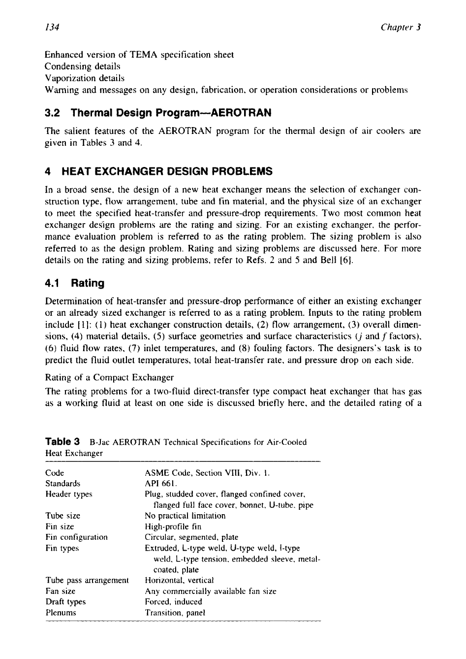
Table
3
B-Jac AEROTRAN Technical Specifications for Air-cooled
Heat Exchanger
Code ASME Code, Section
VIII,
Div.
1.
Standards
API
66
1.
Header types
Plug, studded cover, flanged confined cover,
flanged full face cover, bonnet, U-tube, pipe
Tube size
No practical limitation
Fin size
High-profile fin
Fin configuration
Circular, segmented, plate
Fin types
Extruded, L-type weld, U-type weld, I-type
weld, L-type tension, embedded sleeve, metal-
coated, plate
Tube pass arrangement
Horizontal, vertical
Fan size
Any
commercially available fan size
Draft types
Forced, induced
Plenums
Transition, panel
--
Heat Exchanger Thermal Design
I35
Table
4
B-Jac AEROTRAN Output
Optimization path
Design summary
Performance evaluation
Heat-transfer coefficients
MTDLMTD, heat flux
Pressure drop
Construction
of
bundle
Fan details
Heat exchanger specification sheet
Recap
of
designs
Condensing details
Warnings and messages
crossflow and counter-crossflow exchanger is described separately. Customarily, the E-NTU
method is employed for compact heat exchangers. Hence, the solution procedure is outlined
here using the E-NTU method. The basic steps involved in the analysis of a rating problem are
the determination of:
1.
Surface geometrical parameters
2.
Thermophysical fluid properties
3.
Reynolds numbers
4.
Surface characteristics,
j
and
f
5.
Corrections to the temperature-dependent fluid properties
6.
Heat-transfer coefficients
7.
Fin
effectiveness and overall surface effectiveness
8.
Thermal resistance due to conduction wall
9.
Overall heat-transfer coefficient
10.
NTU,
C*,
and exchanger effectiveness
E
11.
Heat transfer rate, outlet temperatures, and pressure drop on each side
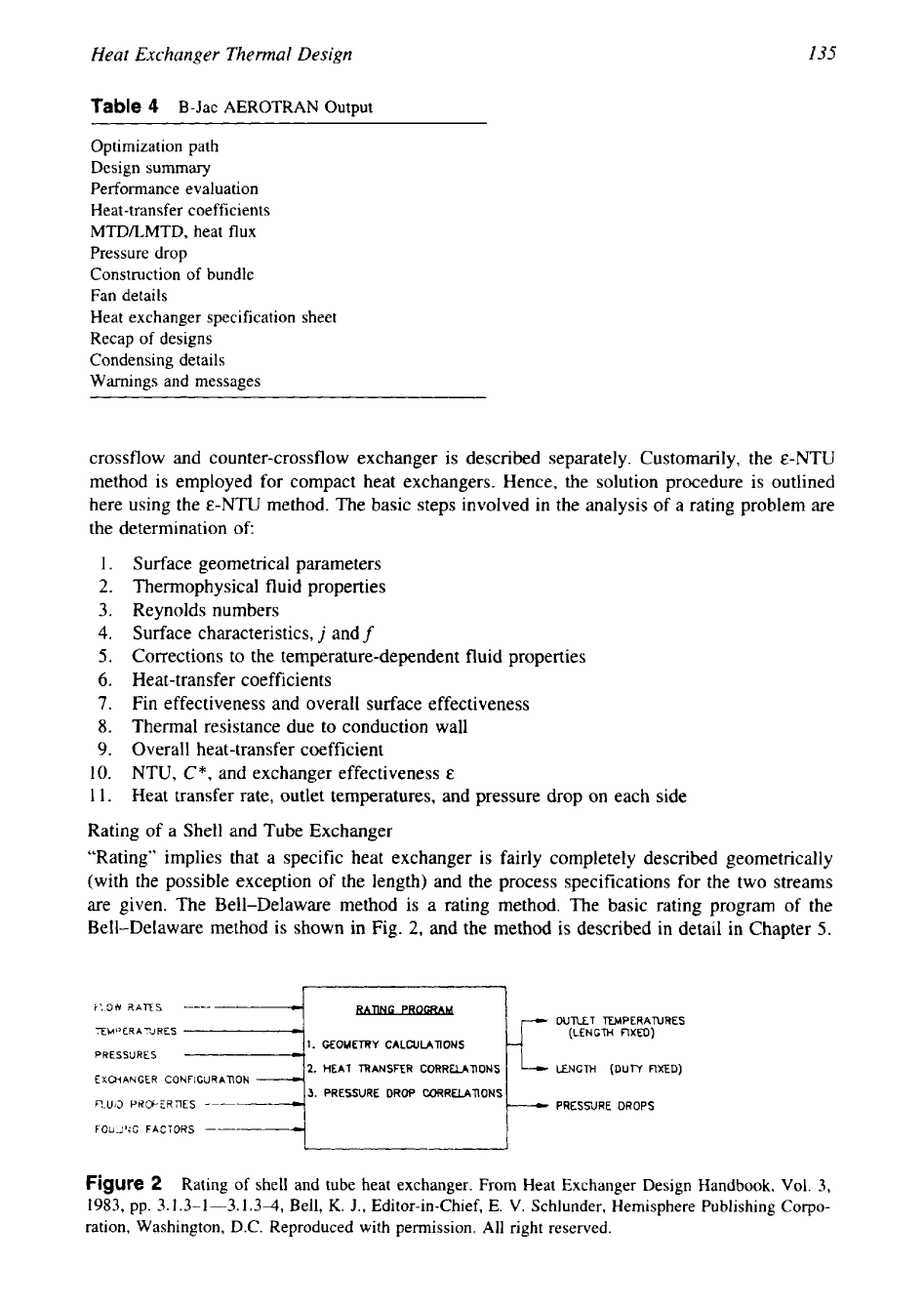
Rating of a Shell and Tube Exchanger
“Rating” implies that a specific heat exchanger is fairly completely described geometrically
(with the possible exception of the length) and the process specifications for the two streams
are given. The Bell-Delaware method is a rating method. The basic rating program
of
the
Bell-Delaware method
is
shown in Fig.
2,
and the method
is
described in detail in Chapter
5.
-
FLOW
RATES
EMPERAXRES
I=j
PRESSURES
1.
GEOMETRY
CALCULATIONS
OUTLET
TUvlPERATURES
(LENGTH
FIXED)
2.
HEAT
TRANSFER CORRELATIONS
EXCHANGER
CONFIGURATION
3.
PRESSURE DROP CORRELATIONS
fl.UID
PRWERTlES
PRESSURE
DROPS
FOULING
FACTORS
-
I
Figure
2
Rating
of
shell and tube heat exchanger. From Heat Exchanger Design Handbook, Vol.
3,
1983,
pp.
3.1.3-1-3.1.3-4,
Bell,
K.
J., Editor-in-Chief,
E.
V.
Schlunder, Hemisphere Publishing
Corpo-
ration, Washington, D.C. Reproduced with permission. All right reserved.
17
136
Chapter
3
1
2
3
4
1
6
7
8
9
10
11
12
13
14
IS
16
17
18
19
20
21
22
23
24
25
26
27
28
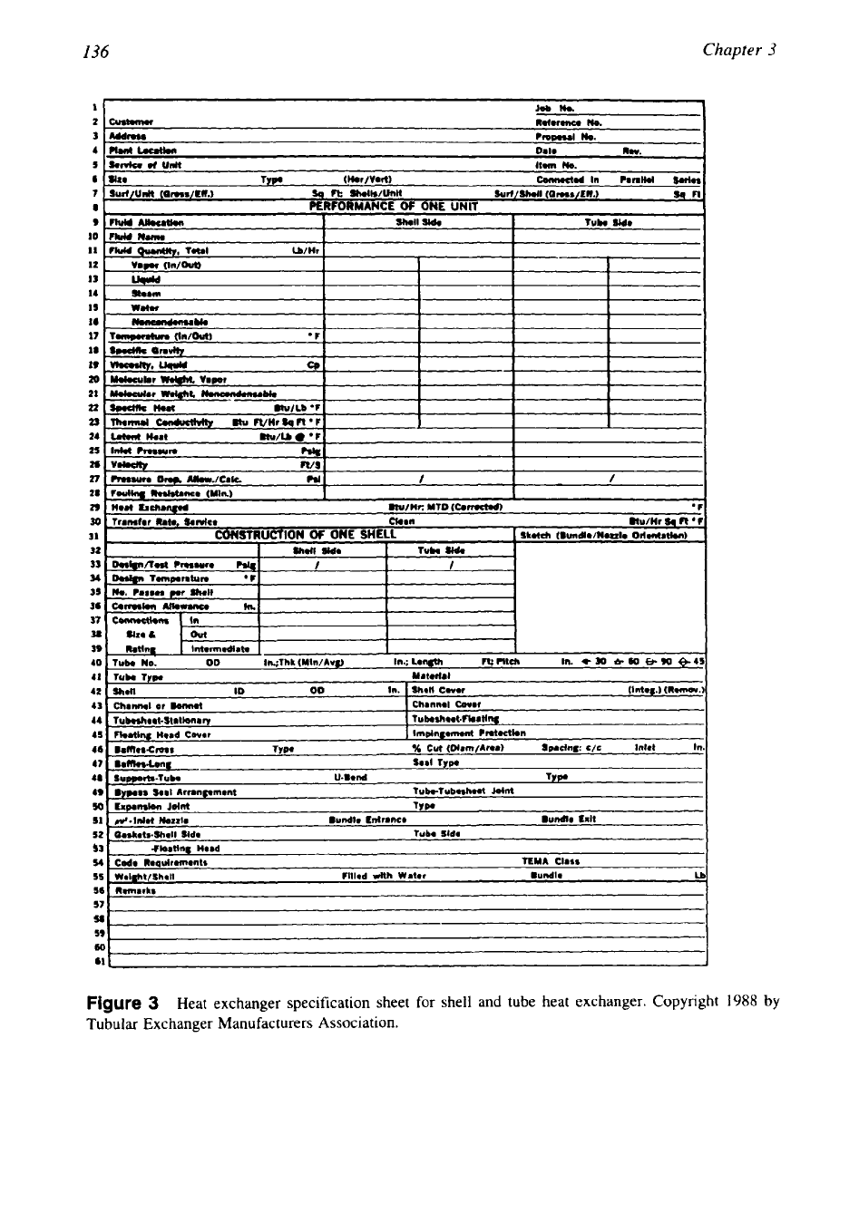
Figure
3
Heat exchanger specification sheet for shell and tube heat exchanger. Copyright
1988
Tubular Exchanger Manufacturers Association.
Heat Exchanger Them1 Design
137
(I.II~NT
JOIJ.
NO
L(
)(’All
ON
Dcsipn
Diitii
Shcct
ITEM
NO.
I%IIC
Fin
I
lcnl
Exchnnpr
2
No.
of
process
strcarndhlcrk
Flow:
cros~countcrlcms~-countcr
No.
blncks
scrlpar
pcr
train
3
DATA
FOR
ONE
TRAIN
4
Strciiin Iticntificiiiim
I
Units
I
A
I
t 3 I
c 1
U 1
E l
F
5
Fluid
Nnnic
1 1 1
1
I
I
I
I I
I I
43
JJ
Wcipht’Plock
-
dry
-
operating
\VciphtrTr;itn
-
operating
-
max
Inr
shipping
I
ti
i
I
I
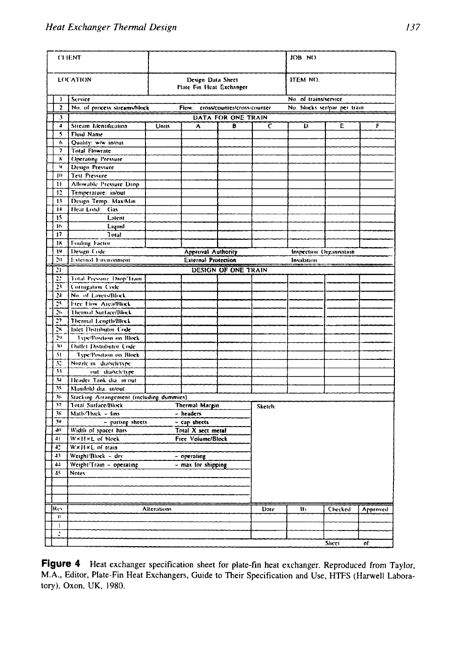
Figure
4
Heat exchanger specification sheet for plate-fin heat exchanger. Reproduced from Taylor,
M.A.,
Editor, Plate-Fin Heat Exchangers, Guide to Their Specification and Use, HTFS (Harwell Labora-
tory), Oxon,
UK,
1980.
I38
Chapter
3
4.2
Sizing
In a sizing problem, we determine the physical size (length, width, height, and surface area on
each side) of an exchanger. Inputs to the sizing problem are the fluid inlet and outlet tempera-
tures, flow rates, fouling factors, and the pressure drop on each side. The designer’s task is to
select construction type, flow arrangement, materials, and surface geometry on each side. With
the selection of construction types and surface geometries on each side, the problem then
reduces to the determination of the core dimensions for the specified heat-transfer and pressure-
drop performance. However, one can reduce the sizing problem to the rating problem by tenta-
tively specifying the dimensions, then predict the performance
[
11.
If the computed results do
not agree with the specified values, a new size
is
assumed and the calculations are repeated.
Size
of
a Heat Exchanger
For a given heat duty, the size of the heat exchanger is a function of the following parameters:
1.
Thermal effectiveness
2.
Fluid flow rate
3.
Secondary surface area per unit volume
4. Heat-transfer surface performance parameters
5.
Heat-transfer augmentation devices, if any
6,
Conductance ratio of the process fluids
Sensitivity Analysis
In a sizing problem, sometimes one is interested
in
determining the sensitivity of certain vari-
ables individually. For example, how does the heat transfer
vary
when changing the fin density
in
a compact heat exchanger with secondary surface? In such a case, one inputs a series of
values of fin densities at one time, runs the performance (rating) calculations, obtains a series
of results, and analyzes them.
Sizing of a Compact Heat Exchanger
The principle of compact heat exchanger sizing is discussed in Chapter
4,
Compact Heat
Exchanger Design.
Sizing of a Shell and Tube Heat Exchanger
Shell and tube heat exchanger design or sizing is based upon
(1)
design conditions, that is,
fluid flow rates, terminal temperatures, thermophysical fluid properties, and allowable pressure
drop;
(2)
assumptions, heat-transfer surface area, overall heat-transfer coefficient, or size,
length, or number of tubes; and
(3)
pressure
drop
across the heat exchanger
[7].
The design
conditions are fixed by overall plant design and determine the expected performance
of
the
exchanger, Trial-and-error calculations of the film coefficients area used to check the assump-
tions, which are also checked by an overall heat balance. Finally, the pressure drop is calculated
and compared with the allowable values. If the calculated pressure drop is too high, a new set
of assumptions
is
made and rechecked as before.
Heat Exchanger Optimization
The solution to the sizing problem in general is not adequate for the design of a new exchanger,
since other constraints in addition to pressure drop are imposed on the design, and the objective
of the design is to minimize the weight, volume, and heat-transfer surface, and minimum
pumping power, pressure drop, or other considerations in addition to meeting the required heat
transfer. This is achieved by heat exchanger optimization. Shah et al.
[8]
reviewed various
methods used in the literature for heat exchanger optimization and described numerical nonlin-
ear programming techniques.
Heat Exchanger Thermal
Design
139
4.3
Solution to the Rating and Sizing
Problem
Now let
us
discuss the basic steps involved in the solution of the two design problems, the
rating and sizing.
Rating
The basic steps involved
in
the solution to the rating problem are as follows
[9].
E-NTU Method.
1.
Compute
C*
and NTU from the input specifications.
2.
Determine
E
for known NTU,
C*,
and the flow arrangement,
3.
Compute
q
from
and outlet temperatures from
and compare with those of step
2.
LMTD Method.
1.
Compute
R
from
R
=
C,/C,.
2.
Assume the outlet temperatures to determine
P,
or assume
P
and calculate outlet tempera-
tures. Also calculate LMTD.
3.
Determine LMTD correction factor,
F.
4.
Determine q from
q
=
UAF(LMTD).
5.
Evaluate the outlet temperatures from known
q,
C,,
and
C,,,
and compare with those of
step
2.
6.
Repeat steps
2-5
until the desired convergence is achieved.
Solution to the Sizing Problem
In a sizing problem,
U,
C,,
Ch,
and the terminal temperatures are specified, and the surface
area
A
is to be determined. Or
U
may be calculated from the specified convective film coeffi-
cients and the fouling resistances. The basic steps involved in sizing
by
the
E-NTU
and LMTD
methods are as follows
[9].
E-NTU Method.
1.
Compute
E
from the specified inlet and outlet temperatures and calculate
C*.
2.
Determine NTU from known
E,
C*,
and the flow arrangement,
3.
Calculate the required surface area
A
from
A
=
(NTU)C,,,/U and from terminal tempera-
tures.
LMTD Method.
1.
Compute
P
and
R
from the specified inlet and outlet temperatures.
2.
Determine
F
from
F-P
curves for known
P, R,
and the flow arrangement.
3.
Calculate the heat transfer rate q and LMTD.
4.
Calculate
A
from
A
=
q/[U
F(LMTD)].
A trial-and-error approach is needed for the solution of the rating problem by the LMTD
method.

140
Chapter
3
5
COMPUTER-AIDED
THERMAL
DESIGN
In the present computer era, thermal design is almost exclusively performed by industry using
computers. Chenoweth et al.
[
101, Bell
[
111, and Palen
[
121 discuss computer-aided design
methods for shell and tube exchangers. Shah [13] discusses in detail the computer-aided ther-
mal design methodology for both compact and shell and tube exchangers. Although there are
similarities in the overall structure of the computer programs, the details
vary
significantly
between compact and shell and tube exchangers. In the following subsections, we discuss the
structure of a computer design method for thermal design of (1) compact heat exchangers and
(2)
shell and tube heat exchangers. Salient features of this computer program are discussed.
5.1
Overall Structure
of
a
Thermal Design Computer Program
The overall structure of a thermal design computer program for a compact heat exchanger (Fig.
5),
consists at a minimum of these subroutines [13]: (1) input subroutines,
(2)
geometry subrou-
tine,
(3)
fluid properties subroutine,
(4)
surface characteristics subroutine,
(5)
fin efficiency
subroutine,
(6)
E-NTU subroutine,
(7)
pressure drop subroutine,
(8)
rating problem subroutine,
(9)
sizing problem subroutine, (10) optimization subroutines, and (1 1) output subroutines.
Input Subroutines.
These serve (1) to feed the problem specifications/process data, and
(2)
to convert the given unit from one system to other. The input subroutine should be structured
to verify whether the input data is within normal ranges and to give a warning message if
any
inconsistency is found.
Geometry Subroutine.
The geometry subroutine calculates the various surface geometrical
parameters for commonly used surfaces. For uncommon surfaces, calculated values are fed
through the input subroutine or the terminal.
Fluid Properties Subroutine.
This subroutine provides fluid properties for commonly used
fluids in the form of specific or generalized correlations together with heat release/added curve.
For others, they may be transferred through input data. Methods or correlations should
be
incorporated for evaluating properties of fluid mixtures.
Surface Characteristics Subroutine.
For common surfaces,
j
and
f
versus Reynolds number
data may be stored in the subroutine, or correlations may be built in. For uncommon surfaces,
such information may be transferred through the input subroutine or through the terminal.
Fin Eficiency Subroutine.
This subroutine calculates the fin efficiency and overall surface
effectiveness for various types of extended surfaces.
E-NTU
Subroutine.
E-NTU formulas for all flow arrangements of interest are built into this
subroutine. The subroutine could be used for solving both the rating and sizing problems. That
means, for a rating problem, it computes
E
when NTU and
C*
are given, and for a sizing
problem it computes NTU when
E
and
C*
are given.
Pressure
Drop
Subroutine.
The friction factor
f
is fed through the surface characteristic sub-
routine. Provisions must be made to compute the pressure drop in manifolds, headers, turns,
or sudden area changes at manifold/header inlet/outlet sections.
Rating Problem Subroutine.
Since outlet temperatures are not known initially, they are there-
fore guessed, and the solution to the rating problem is iterated on the fluid properties once or
twice until the desired convergence is achieved.
Sizing Problem Subroutine.
All of the subroutines (except the rating problem subroutine)
discussed so far are used in sizing problem. The sizing problem is solved by first determining
Heat Exchanger Thermal Design
141
an approximate mass velocity
G
that accounts for both specified heat transfer and pressure
drop. The sizing problem is iterated on
G
until the desired convergence is met.
Optimization Subroutines.
In a sophisticated computer program, not only are the options of
solving straightforward rating and sizing problems available, but also optimization procedures
are incorporated. Such a program logically searches among feasible solutions and arrives at an
optimum objective function.
Output Subroutines.
These serve to print all the output results in the desired units along with
the desired input data and error messages. All important output results should be verified for
their basic validity.
Guidelines on Program Logic
Shah
[
131 lists several points that should be taken into account in the initial organization and
writing of the program:
1. The program should be written in a modular form containing many subroutines rather than
one big main program. This allows flexibility in thorough debugging and modification of
the program while running the program.
2.
Error messages subroutines should
be
inbuilt that monitor the warning and minor and
major errors for the input data and throughout the problem execution.
3.
All of the iterative calculations should have a maximum number of iterations specified.
4.
For a sophisticated computer program to be good, it must satisfy the requirements of
individuals with diverse yet specific interests. The program should provide correct answers
and ease of use, and it will be viable only as long its developers provide user support
[
101.
5.2
Program Structure for a Shell and Tube Exchanger
For a shell and tube exchanger, most of the structure of the subroutines mentioned
so
far are
common but the contents slightly
vary
as follows:
1.
Geometry subroutine: This should include the auxiliary calculations on the shell side and
a range of geometries including the shell type, number
of
shells
in
series, number
of
shells
in parallel, shell diameter, tube length, baffles and baffle cut, various shell-side clearances,
tube count, and nozzles.
2.
Various shell-side correction factors calculated for heat transfer and pressure drop.
3.
The thermal effectiveness subroutine:
P-NTU,
relations should be built in for all possible
flow arrangements and TEMA shells, including the check for “temperature cross.”
6
PRESSURE-DROP ANALYSIS, TEMPERATURE-DEPENDENT
FLUID PROPERTIES, PERFORMANCE FAILURES, FLOW
MALDISTRIBUTION, FOULING, AND CORROSION
6.1
Heat Exchanger Pressure-Drop Analysis
The term “pressure drop” refers to the pressure loss that is not recoverable in the circuit. The
determination of pressure drop in a heat exchanger is essential for many applications for at
least two reasons [9]:
1.
The operating cost of a heat exchanger is primarily the cost of the power to run fluid-
moving devices such as pumps, fans, and blowers. This pumping power,
P,,,
is proportional
to the exchanger pressure drop as given by
142
Chapter
3
P,
-MAP
-
__
P
where
M
is the mass flow rate,
Ap
is
the pressure drop, and
Q
is the fluid density.
2.
The heat-transfer rate can be significantly influenced
by
the saturation temperature change
for a condensing/evaporating fluid for a large pressure drop.
The principle
of
pressure-drop analysis for a heat exchanger is described by Kays
[14}
and is extended to all types of heat exchangers. In this section, pressure-drop analysis for
various types
of
heat exchangers as per Ref.
9 is
discussed.
Pressure Drop Evaluation for Heat Exchangers
The pressure drop associated with a heat exchanger may be considered as having two major com-
ponents:
(1)
pressure drop associated with the core or matrix, and
(2)
pressure drop in inlet and
outlet headers, manifolds, nozzles, or ducting due
to
change in flow area, flow turning, etc. In this
section, core pressure drop for extended surface exchangers, regenerators, and tubular exchangers
is presented, followed by the pressure drop associated with bends and flow turnings.
Pressure Drop Through a Heat Exchanger
The pressure drop on any one side consists
of
pressure losses due to sudden contraction at the
core inlet,
Ap,.?,
core pressure drop,
Ap2-3,
and the pressure rise due to sudden expansion at
the core outlet,
Ap3.+
Therefore, the total pressure drop on any one side of the exchanger
is
given by
Ap
=
ApI.2
+
Ap2.7
-
Ap7-j
(2)
Pressure drop through a heat exchanger is schematically shown in Fig.
6.
This figure is based
on Ref.
14.
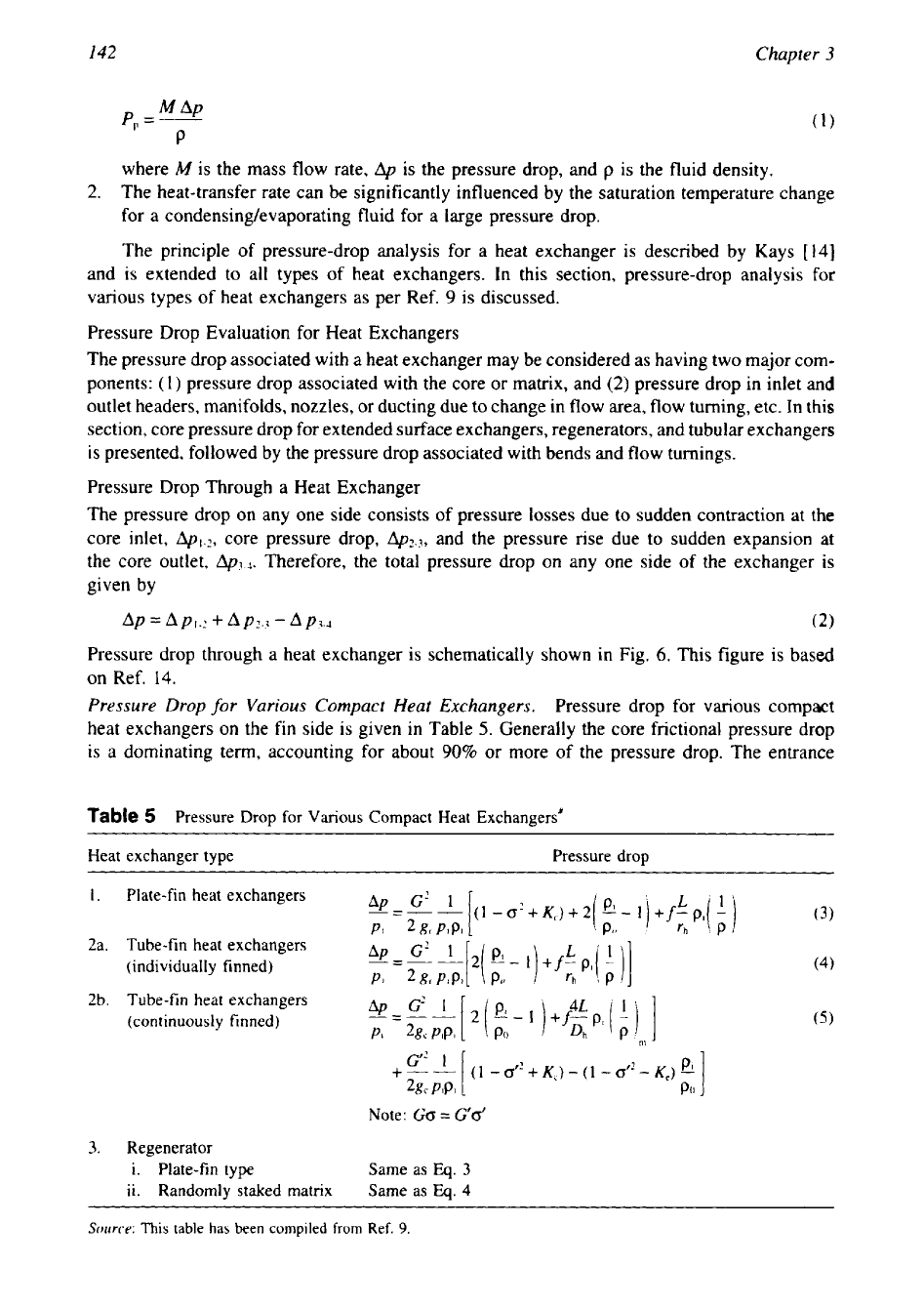
Pressure Drop for Various Compact Heat Exchangers.
Pressure drop for various compact
heat exchangers on the fin side is given in Table
5.
Generally the core frictional pressure drop
is a dominating term, accounting for about
90%
or more of the pressure drop. The entrance
Table
5
Pressure Drop
for
Various Compact Heat Exchangers’
Heat exchanger type Pressure drop
1.
Plate-fin heat exchangers
(3)
2a. Tube-fin heat exchangers
(individually finned)
(4)
2b. Tube-fin heat exchangers
(continuously finned)
PI
2gc
PIP1
4L
Note:
Go
=
G’d
3.
Regenerator
i.
Plate-fin type Same as
Eq.
3
ii. Randomly staked matrix
Same as
Eq.
4
Source:
This
table
has
been compiled from Ref.
9.
143
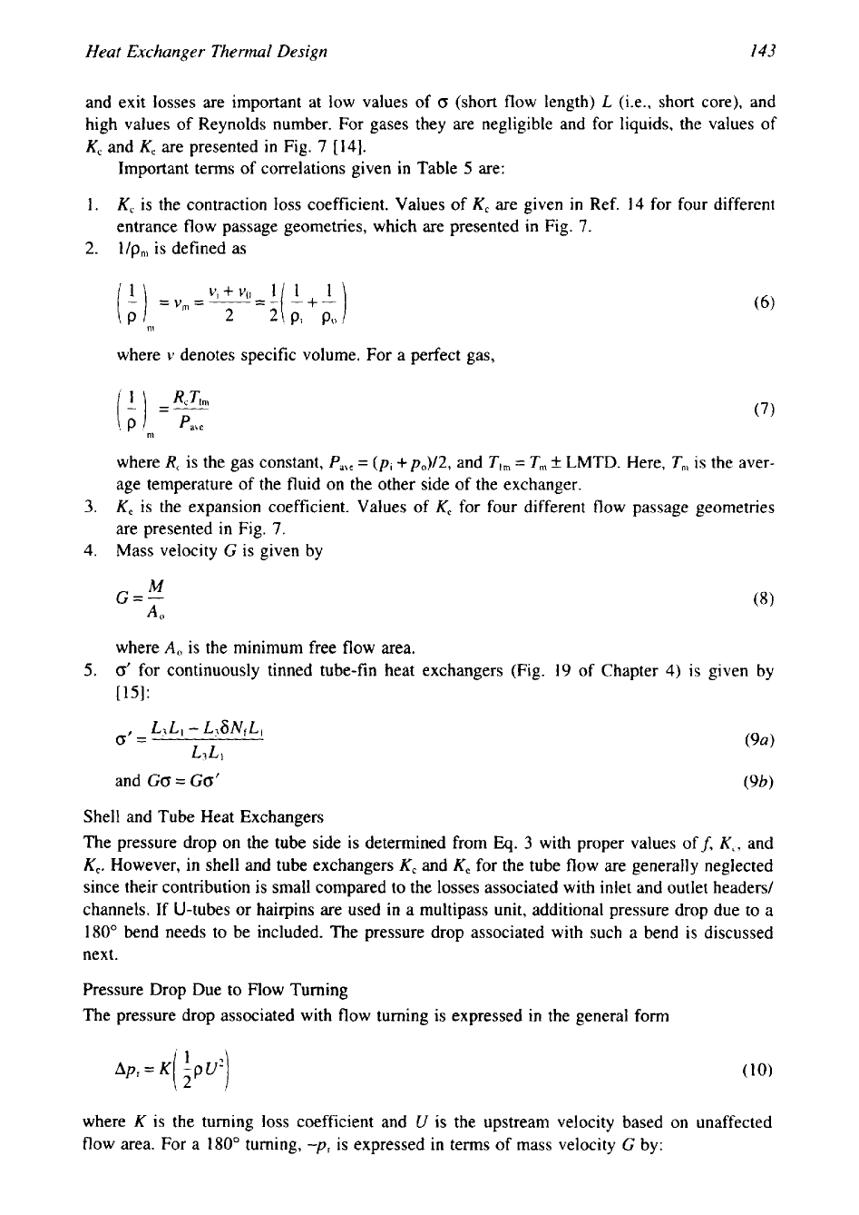
Heat Exchanger Thermal Design
and exit losses are important at low values of
0
(short flow length)
L
(i.e., short core), and
high values of Reynolds number. For gases they are negligible and for liquids, the values of
K,
and
K,
are presented in Fig.
7
[
141.
Important terms of correlations given in Table
5
are:
1.
K,
is the contraction loss coefficient. Values of
K,
are given in Ref.
14
for four different
entrance flow passage geometries, which are presented in Fig.
7.
2.
l/p,,,
is defined as
where
v
denotes specific volume. For a perfect gas,
(7)
where
R,
is the gas constant,
Pabe
=
(p,
+po)/2,
and
Tlm
=
T,,,
k
LMTD. Here,
T,
is the aver-
age temperature
of
the fluid on the other side of the exchanger.
3.
K,
is the expansion coefficient. Values of
K,
for four different flow passage geometries
are presented in Fig.
7.
4.
Mass velocity
G
is given by
where
A,
is the minimum free flow area.
5.
0'
for continuously tinned tube-fin heat exchangers (Fig.
19
of Chapter
4)
is given by
[15]:
Shell and Tube Heat Exchangers
The pressure drop on the tube side is determined from
Eq.
3
with proper values off,
K,,
and
K,.
However, in shell and tube exchangers
K,
and
K,
for the tube flow are generally neglected
since their contribution
is
small compared to the losses associated with inlet and outlet headers/
channels. If U-tubes or hairpins are used in a multipass unit, additional pressure drop due
to
a
180"
bend needs to be included. The pressure drop associated with such a bend is discussed
next.
Pressure Drop Due to mow Turning
The pressure drop associated with flow turning is expressed in the general form
where
K
is the turning loss coefficient and
U
is the upstream velocity based
on
unaffected
flow area. For a
180"
turning,
-pr
is
expressed in terms of mass velocity
G
by: