Kuppan T. Heat Exchanger Design Handbook
Подождите немного. Документ загружается.

0
d,
..n
a
CQ
m
CQ
a
c
CQ
3
I-
2
115
Heat Exchanger Therrnohydraulic Fundamentals
f0
09
08
0.7
0.6
05
0.4
0.3
0.2
0.1
0.0
NTU
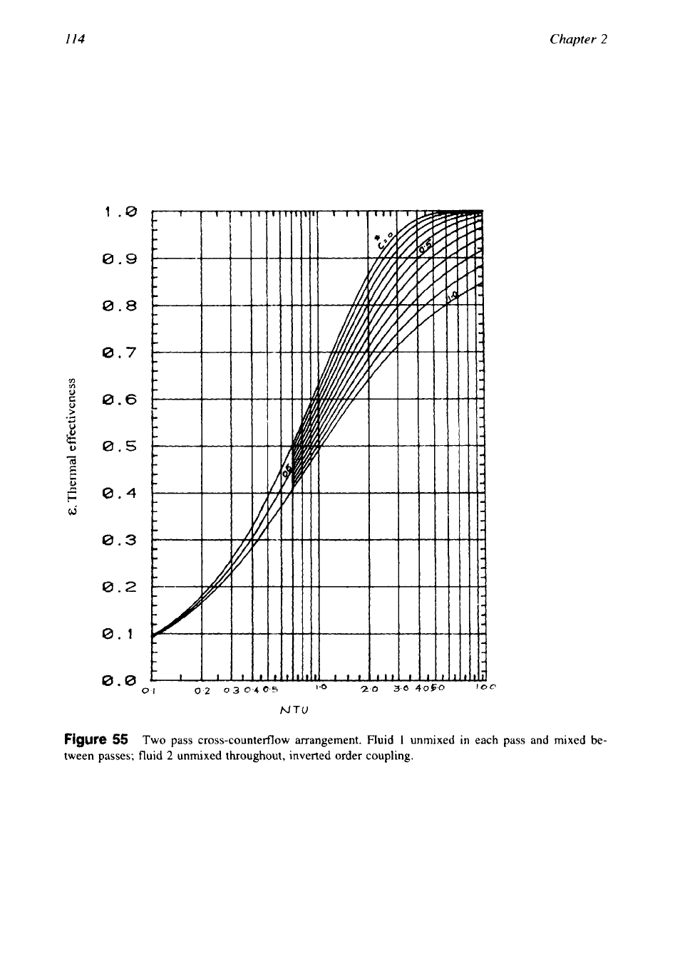
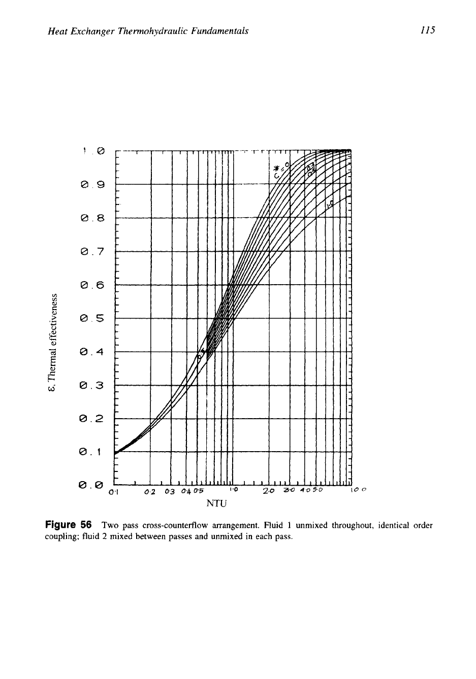
Figure
56
Two pass cross-counterflow arrangement. Fluid
1
unmixed throughout, identical order
coupling; fluid
2
mixed between passes and unmixed
in
each pass.
c
(D
U)
b
L
8
8
6)
E,
Thermal effectiveness
3
E.
a
c.
3
E.
Q
t4
0
118
Chapter
2
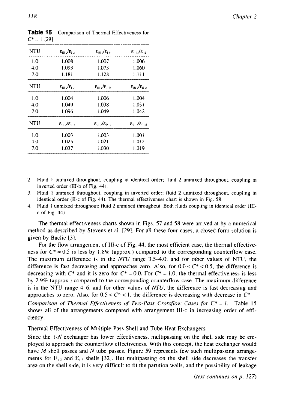
Table
15
Comparison of Thermal Effectiveness for
C*=
1
[29]
1
.o
1.008 1.007 1.006
4.0
1.093
1.073
1.060
7.0
1.181
1.128
1.1 11
1
.O
1.004 1.006
I
.004
4.0
1.049 1.038 1.03
1
7.0
1.096 1.049 1.042
1
.0 1.003 1.003 1.001
4.0
1.025
1.02
1
1.012
7.0 1.037 1.030 1.019
2.
Fluid
1
unmixed throughout, coupling in identical order; fluid
2
unmixed throughout, coupling in
inverted order
(111-b
of
Fig.
44).
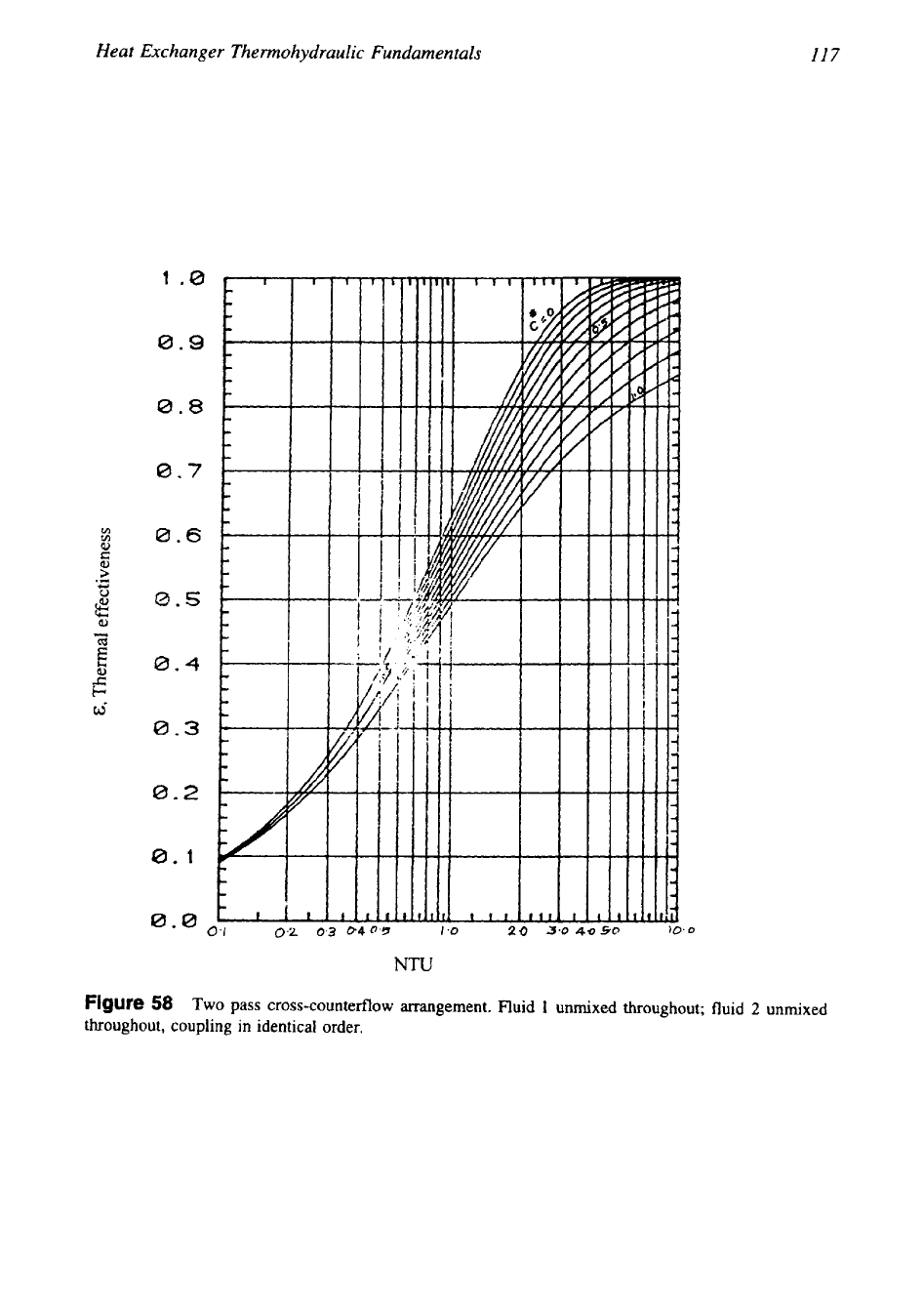
3.
Fluid
1
unmixed throughout, coupling in inverted order; fluid
2
unmixed throughout, coupling in
identical order
(11-c
of Fig.
44).
The thermal effectiveness chart is shown in Fig.
58.
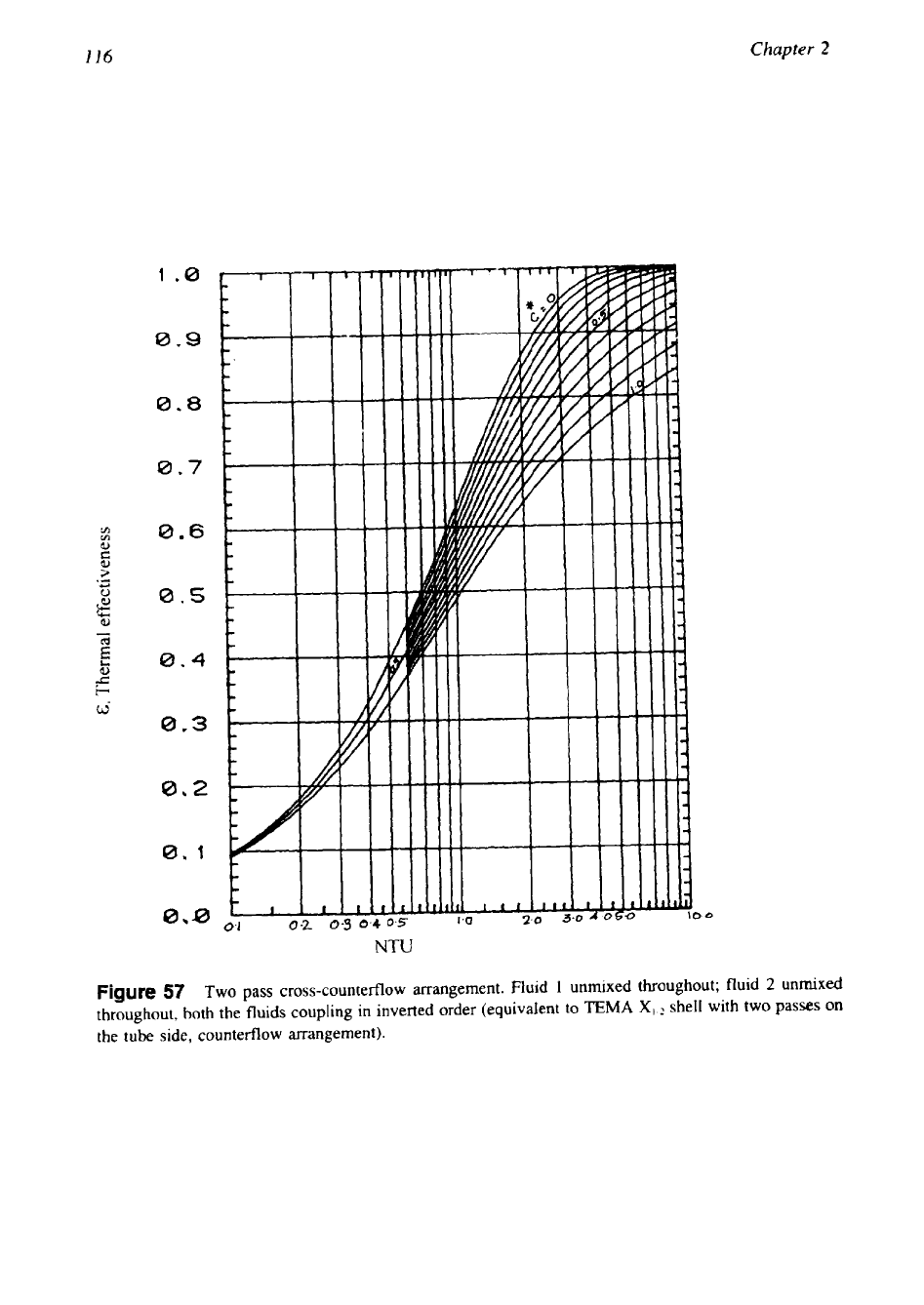
4.
Fluid
1
unmixed throughout; fluid
2
unmixed throughout. Both fluids coupling in identical
order
(111-
c
of Fig.
44).
The thermal effectiveness charts shown in Figs.
57
and
58
were arrived at by a numerical
method as described by Stevens et al. [29]. For all these four cases, a closed-form solution is
given by Baclic
[3].
For the flow arrangement of 111-c of Fig.
44,
the most efficient case, the thermal effective-
ness for
C*
=
0.5
is less by
1.8%
(approx.) compared to the corresponding counterflow case.
The maximum difference
is
in
the
NTU
range 3.5-4.0, and for other values of
NTU,
the
difference is fast decreasing and approaches zero. Also, for
0.0
<
C*
<
0.5,
the difference is
decreasing with
C*
and
it
is zero for
C*
=
0.0.
For
C*
=
1.0,
the thermal effectiveness is less
by 2.9% (approx.) compared to the corresponding countefflow case. The maximum difference
is
in
the NTU range
4-6,
and for other values of
NTU,
the difference is fast decreasing and
approaches to zero. Also, for
0.5
<
C*
<
1,
the difference is decreasing with decrease
in
C*.
Comparison
of
Thermal EfScuctiveness
of
Two-Pass Crossflow Cases
for
C*
=
1.
Table
I5
shows all of the arrangements compared with arrangement 111-c
in
increasing order of effi-
ciency.
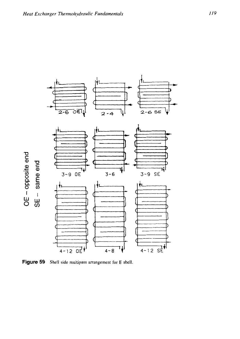
Thermal Effectiveness of Multiple-Pass Shell and Tube Heat Exchangers
Since the
1-N
exchanger has lower effectiveness, multipassing on the shell side may
be
em-
ployed to approach the counterflow effectiveness. With this concept, the heat exchanger would
have
M
shell passes and
N
tube passes. Figure
59
represents few such multipassing arrange-
ments for
E,.?
and
E,.i
shells [32]. But multipassing on the shell side decreases the transfer
area on the shell side,
it
is very difficult to fit the partition walls, and the possibility of leakage
(text continues
on
p.
127)
119
c
Heat Exchanger The
nno
h
y
dra
u
1
ic
Fundamen ta
Is
m
2-6
U
-+I
3-6
--+I
3-9
OE
3-9
SE
-7
+I
4-12
SE
Figure
59
Shell
side
multipass
arrangement
for
E
shell.
-4
120
Chapter
2
I
i
I t
I 1
I I
I
i
WELLS
EE2-?
SHELLS
I
I I
SHELLS
I
L)
I
SHELLS
I
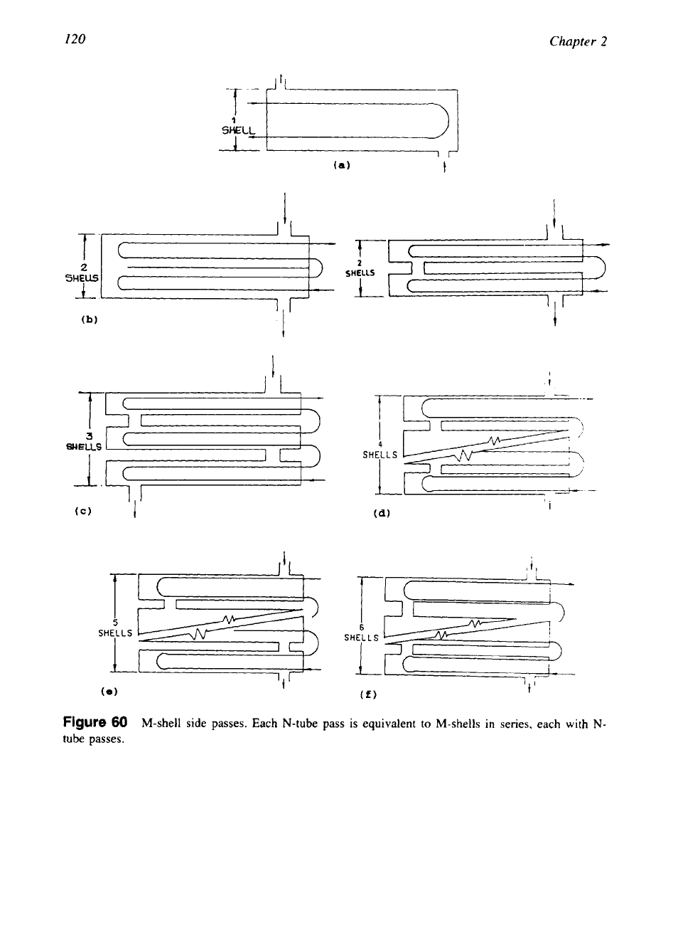
Figure
60
M-shell side passes. Each
N-tube
pass
is
equivalent
to
M-shells
in
series, each
with
N-
tube
passes.
Heat Exchanger Thermohydraulic Fundamentals
121
I
.e
8.8
8.5
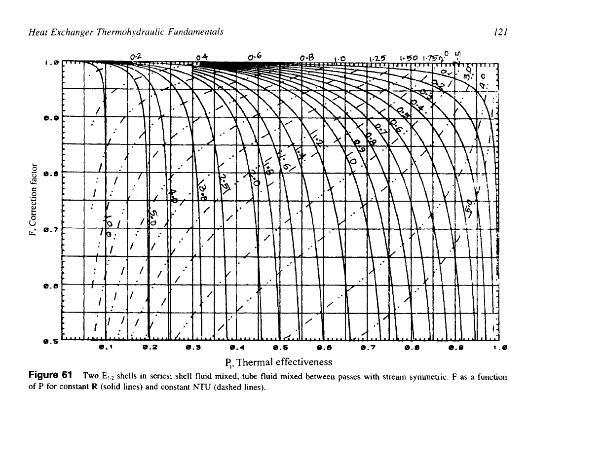
Figure
of
P
for
I22
Chapter
2
c
U
E
li
0.2
0.6
e.7
0.0
8.8
c,
Thermal effectiveness
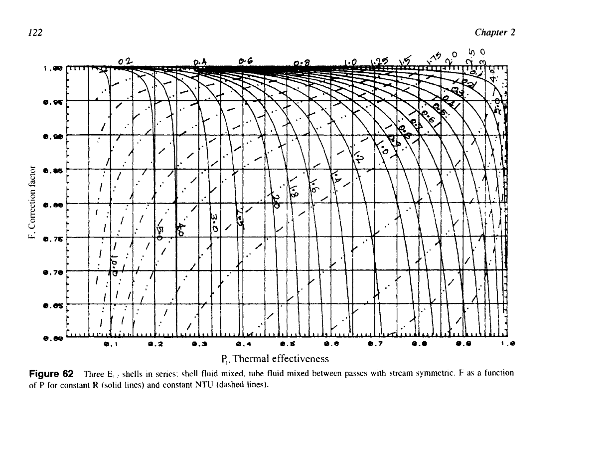
Figure
62
Three
E,
shells in series; shell fluid mixed, tube fluid mixed between passes with stream symmetric.
F
as
a function
of
P
for
constant
R
(solid lines) and constant
NTU
(dashed lines).
123
Heat Exchanger Thennohydraulic Fundamentals
0.0s
8.80
0.
e3
0.m
8.75
0.7e
0.6S
0.60
8.1
8.2
8.3
8.4
0.5
0.6
0.7
0.8
8.9
1
.e
pl.
Thermal effectiveness
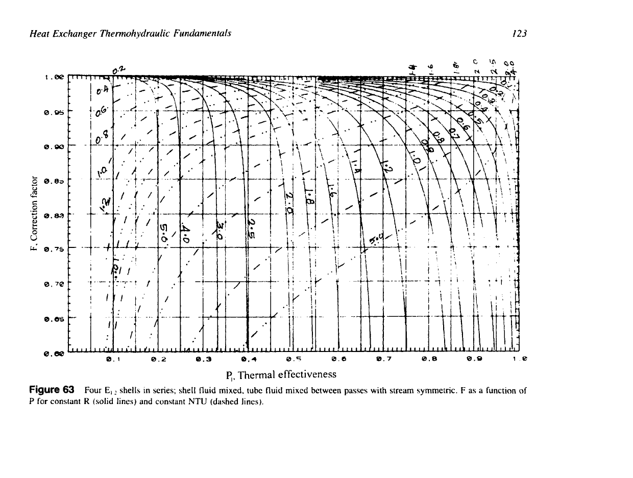
Figure
63
Four
E,
shells in series; shell fluid mixed,
tube
fluid mixed between
passes
with
stream
symmetric.
F
as
a function of
P
for constant
R
(solid lines) and constant
NTU
(dashed lines).