Kristiansen Svein. Maritime Transportation: Safety Management and Risk Analysis
Подождите немного. Документ загружается.

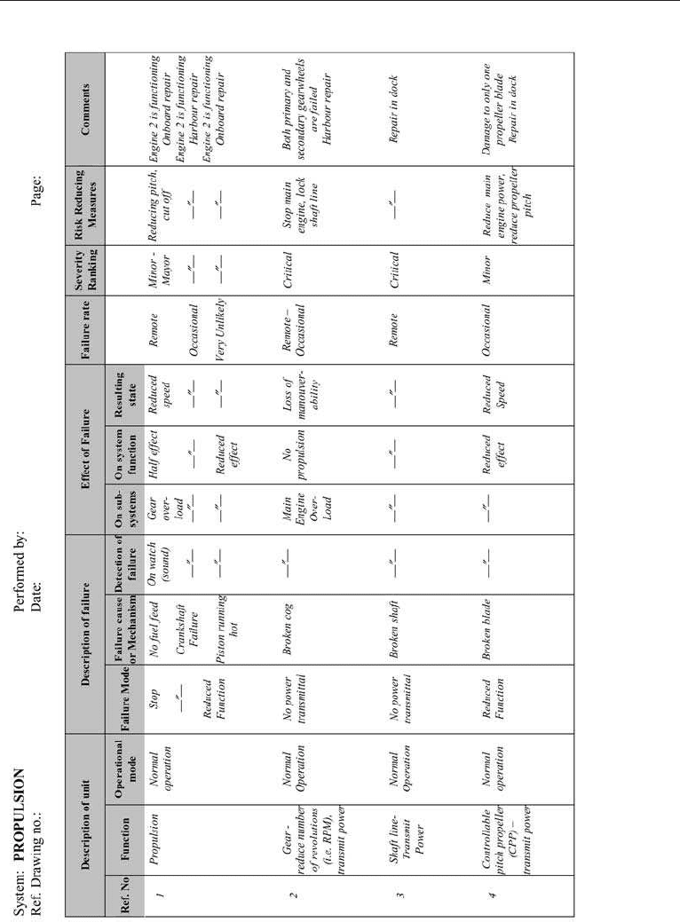
Figure 8. 9. FMECA form.
226 CHAPTER 8 RISK ANALYS IS TECHNI QU ES
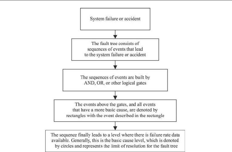
the causes of the event (e.g. the failure of a certain engine component) is visualized. The
method assumes binary operational modes, which means that an event either occurs or it
does not (e.g. a failure alarm is given or not given). Hence, degraded operations or events
are not analysed in fault trees.
The logical diagram used in an FTA consists of a set of gate symbols that describe the
relationship betw een causes, and event symbols that characterize the causes. These gate
and event symbols are described later in this section. The main principles of the fault tree
analysis method are illustrated in Figure 8.10.
8.7.2 Approach
A fault tree can be analysed both qualitatively and quantitatively. Thes e approaches are
described in more detail later.
8.7.3 Elements
The fault tree is a visualization of the relationship between the failures of the analysed
system (see Figure 8.10). This visualization is based on logical gates and symbols. The
most common fault tree gate symbols and event symbols are presented in Tables 8.11 and
Figure 8.10. Principles of a fault tree.
8.7 FAULT TREE ANALY S IS ( FTA) 227
8.12, respectively. The use of the most frequently used gate and event symbols will be
illustrated by an exampl e later in this section.
8.7.4 Qualitative Approach: Construction
The first task of a fault tree analysis is to describe the system and its components/
subsystems down to a sufficient level of detail (see Sectio n 8.3 of this chapter). The next
task is to construct the fault tree for a particular unwanted system failure using this
system description. It is important that all the failures in the fault tree are given precise
definitions. The unwanted event or accident target for the analysis is referred to as the top
event of the fault tree. The description of the top event should give answers to what the
event is, where it occurs and when it occurs.
The occurrence of the top event is always dependent on two or more conditions
or failures on a more detailed, i.e. lower, level. The main task in the FTA approach is to
systematically define and structure the conditions or causes that directly lead to the top
event. These events should be defined in such a way that only a limited number of causes
lead to the top event. Some literature recommends only defining two causes on the lower
level at a time, but for some complex system failures this may not be realist ic. The causes
directly leading to the top event are at the second level in the fault tree.
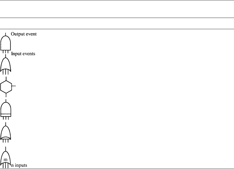
Ta b l e 8 . 11. Fault tree gate symbols
Gate symbol Gate name Casual relation
AND gate Output event occurs if all input events occur
simultaneously
OR gate Output event occurs if any one of the input events occurs
Inhibit gate Input produces output when conditional events occur
Priority AND gate Output event occurs if all input events occur in the order
from left to right
Exclusive OR gate Output event occurs if one, but not more than one, input
events occur
m out of n gate Output event occurs if m out of n input events occur
228 CHAPTER 8 RISK ANALY SIS TECHN IQU ES
When the events are defined and structured, the next task is to assess the logical
relation between the causes. Generally, either the top event is dependent on a simultaneous
occurrence of these causes on the second level, or only one of the causes may lead to the
top event. In the first case an AND gate is used and in the last case an OR gate is used (see
Table 8.11). This procedure is then repeated to establish the logical relations between the
causes on the third level of the fault tree, and so on. When the causes are described in such
a detail that failure data (i.e. failure frequency) is available, the fault tree construction is
finished and ready for quantitative analysis.
8.7.5 Qualitative Approach: Minimal Cut Sets
The objective of qualitative FTA is to establish a general view and understanding of the
fault tree construction. This can be achieved by establishing sets of events that have
special characteristics. A set of basic events in the fault tree that triggers the top event by
occurring simultaneously is called a cut set of the fault tree. For illustration purposes,
a simple fault tree for the top and unwanted event of an initiation of fire can be studied
(see Figure 8.11). Based on basic fire theory, a fire can occur only if three basic conditions
are satisfied. These three basic conditions are the presence of a combustible material
(e.g. wood, oil, etc.), oxygen, and an ignition source (e.g. flame, heat, friction, a spark,
etc.). By distinguishing between combustible substances and gases, the following simplified
fault tree can be constructed.
As shown in the fault tree, a fire can occur if the following set of causes are occurri ng:
{Combustible substance present, Combustible gas present, Oxygen present, Heat or ignition
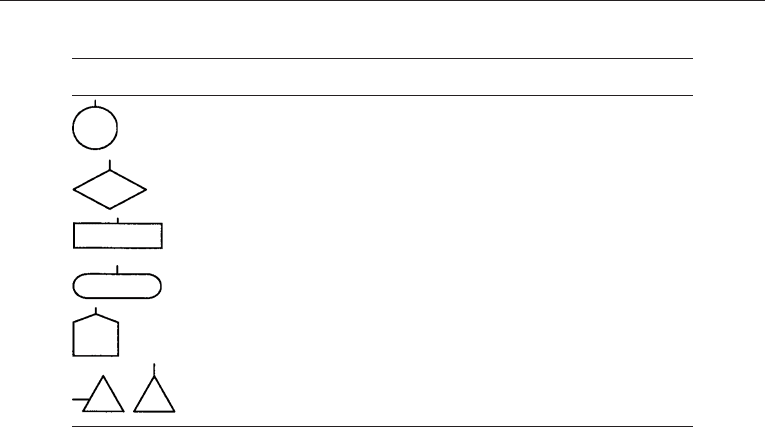
Ta b l e 8 .1 2 . Fault tree event symbols
Event symbol Meaning of symbol
Basic event with sufficient data
Undeveloped event
Event represented by a gate
Conditional event used with inhibit gate
House event. Either occurring or not occurring
Transfer symbol
8.7 FAULT TREE ANALY S IS ( FTA) 229
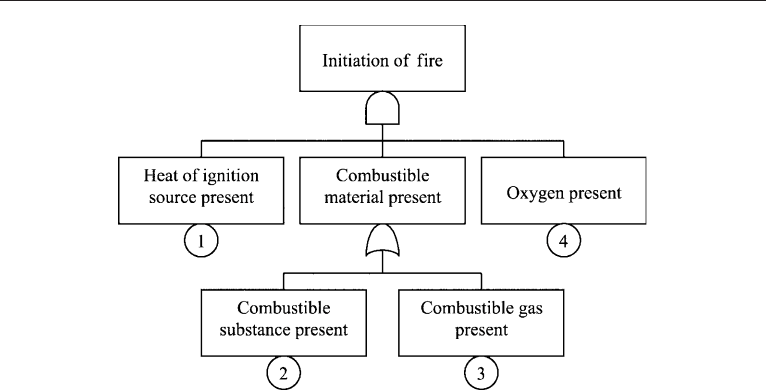
source present}. This is a cut set for this fault tree because the simultaneous occurrence of
the four cau ses results in the occurrence of the top event {Initiation of fire}.
A Minimal cut set is a set of causes where none of the included causes can be excluded
without the causes losing their status as a cut set. Hence, the following two sets of causes
are minimal cut sets: {Combustible material present, Oxygen present, Heat or ignition
source present} and {Combustible gas present, Oxygen present, Heat or ignition source
present}.
To establish the cut sets of a fault tree a systemized algorithm called MOCUS –
Method of Obta ining Cut Sets – can be applied. The MOCUS algorithm is represented by
four steps:
1. Consider the top event.
2. Replace the event with the events on the second level according to the following
criteria: If the events on the lower level are connected through an OR gate they are
written in separate rows. If they are connected through an AND gate they are written
in separate columns.
3. Perform step 2 successively for all events that are not basic events (see Table 8.12).
4. When all events are basic events the events in each row constitute a cut set.
The fault tree in Figure 8.11 can be used to illustrate the use of the MOCUS algorithm.
The starting point of the algorithm is the top event according to step 1. In the fault tree in
Figure 8.11 this is the following event:
fInitiation of fireg
Figure 8.11. Simplified fault tree for a fire.
230 CHAPTER 8 RISK ANALYSIS TECH NIQ UES

This event is then replaced by the events on the lower level according to step 2. Because the
events on the second level of the fault tree are connected through an AND gate, they
replace the top event in three columns:
Cause 1 Combustible material present Cause 4
The causes 1 and 4 are basic events and are not treated any further, according to step 2
in the MOCUS algorithm. However, the event of {Combustible material present}
needs another loop of the MOCUS algorithm in order to complete the cut sets. Because
the gate beyond this event is an OR gate, the causes on the third level are written in
separate rows. Hence according to the MOCUS algorithm the cut sets after the second
loop are:
K
1
Cause 1 Cause 2 Cause 4
K
2
Cause 1 Cause 3 Cause 4
According to step 4 of the algorithm, each row constitutes a cut set, and hence there
are two cut sets, K
1
and K
2
, for the fault tree in Figure 8.11. Consequently, the general
conditions for a fire, i.e. the event {Initiation of fire}, are satisfied when, for example,
Cause 1, Cause 2 and Cause 4 occur simultaneously. Because none of the causes in the two
cut sets can be removed without them losing their status as cut sets, both K
1
and K
2
are minimal.
Another important term in the fault tree terminology is the so-called path set. A path
set assembles a set of causes with the characteristic that non-occurrence of the causes in
the path sets ensure that the top event does not occur. For the fault tree in Figure 8.11
the non-occurrence of Cause 1 {Heat or ignition source present} ensures that the top event
does not occur. Hence Cause 1 is a path set.
Both the minimal path sets and the minimal cut sets give important information
about the properties of the system. The number of elements in the minimal cut sets should
be as large as possible to avoid tri ggering of the top event due to a few causes. Barriers
may be built into the system to achieve this. The number of path sets should be large
because this implies that the system is designed to have multiple ways of avoiding the
top event.
8.7.6 Quantitative Approach: Calculation
The quantitative analysis of the fault tree uses the failure probability q
i
of the basic events
and the fault tree gates to calculate the probability of the top event Q
0
. This calculation is
quite straightforward. For basic events combined through an OR gate the series structure
8.7 FAULT TREE ANALY S IS ( FTA) 231

equation established in Section 8.3 of this chapter is used. For events combined through
an AND gate the parallel structure equation is used (when using these equations it
must be remembered that the reli ability p
i
¼1 q
i
, where q
i
is the failure probability).
Consequently it is easier to trigger events combined through an OR gate than events
combined through an AND gate. Conditional probabilities (i.e. AND gates in fault trees)
are generally very common in fault tree calculations.
8.7.7 Q uantitative Appr oach: Assessment
In the qualitative analysis the minimal cut sets of the fault tree are established. Each of
these cut sets includes one unique set of basic events, whi ch by occurring simultaneously
trigger the top event. Consequently it is important to prevent the occurrence of a basic
cause (or basic event) that is present in several cut sets in order to reduce the likelihood of
top event occurrence. Because the basic causes are present in several cut sets, this may be
applied to calculate a measure of importance for each basic cause. A common importance
measure applied on fault trees is the Vessley-Fussell measure of importance, I
VF
. This
is the probability that at least one minimal cut set that contains the basic event i is failed at
time t, given that the top event is triggered at time t. This can be calculated by the
following equation:
I
VF
ði jtÞ¼PðAt least one of the cut sets containing the basic event i is
failed at time t jThe system is failed at time tÞ
Hence:
I
VF
ði jtÞ¼
Q
Ki
ðtÞ
Q
0
ðtÞ
ð8:5Þ
where Q
Ki
¼the probability that one minimal cut set containing the basic cause i is failed
at time t,andQ
0
¼probability of occurrence for the top event.
The m minimal cut sets in which the basic cause i is present are not independent
because the same basic causes may be present in more than one cut set. However, by
assuming that the m cut sets are independent, the higher limit of Q
Ki
can be estimated
using the I
VF
(i | t) equation above and the parallel structure equation presented earlier.
This assumption is implemented in the following equation:
I
VF
ði jtÞ
1
Q
m
j¼1
ð1 Q
Ki, j
ðtÞÞ
Q
0
ðtÞ
ð8:6Þ
where m ¼number of minimal cut sets where basic cause i is present.
232 CHAPTER 8 RISK ANALYSIS TECH NIQ UES

Exam p le
Problem
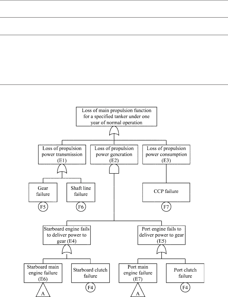
The failure modes of a tanker’s main propulsion system have been established earlier in
the chapter using a FMECA analysis. The connections and relations between the failures
are unknown, and must therefore be modelled in a fault tree. Construct a fault tree where
the top event is loss of propulsion power for the tanker. Then perform a qualitative and
quantitative fault tree analysis using the algorithms and methods described in this chapter.
Solution
It is assumed that the information shown in Table 8.13 is commonly available and known.
Q ualitative approach: fault tree construction
The top event is already defined as ‘loss of propulsion for the tanker’. A simple way to
break down the propulsion system is to emphasize on power transition in the main
propulsion system. There are three independent events that may result in the top event.
These are the ‘loss of propulsion power transmission’ in the shaft lines or gear, ‘loss of
propulsion power generation’ from the engines, and ‘loss of propulsion power
consumption’ due to propeller failure. Only one of these events has to occur in order to
trigger the top event. Hence these three events have to be combined by an OR gate.
The fault tree can be structured as shown in Figure 8.12.
The ‘loss of propulsion power transmission’ event in Figure 8.12 can be caused by gear
failure and/or shaft line failure (see FMECA in Figure 8.9), and must therefore be
combined through the use of an OR gate. The ‘loss of propulsion power consumpt ion’
event only includes the event of controllable pitch propeller (CPP) failure. In terms of the
event of ‘loss of propulsion power generation’, both the starb oard and port engines must
fail to deliver power to the gear. An AND gate must therefore be used for these two
events. There are two ways each engine can fail to deliver power to the gear: by failure of
the clutch and by failure of the engine itself. An OR gate must be used for these events
because one is sufficient for the engine to fail to deliver power to the gear. The events of
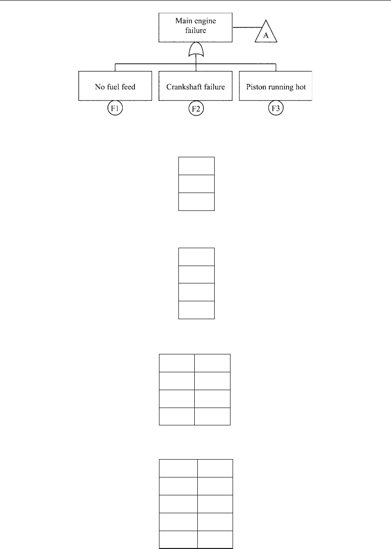
main engine failure (both starboard and port engines) in Figure 8.12 need to be treated
in further detail. According to the FMECA, the causes or basic failure events 1, 2 and 3
(see Table 8.13) are all gathered in the ‘main engine failure’ event, and these have to be
combined through the use of an OR gate since one of the causes is enough for the main
engine to fail. The main engine failure modes can be arranged/modelled in a fault tree
as shown in Figure 8.13.
Q uali tative approach: establ ishi ng mi nimal cut sets
The MOCUS algorithm is applied (subscript s ¼Starboard, subscript p ¼Port):
MOCUS step 1:
‘Loss of main propulsion power for a specified tanker under one year of normal operation.’
8.7 FAULT TREE ANALY S IS ( FTA) 233
Ta b l e 8 . 13 . Failure data calculated for a sailing operation of one year (336 days)
Failure Failure description Reliability
probability p
Failure
probability q
F1 No fuel feed 0.730 0.270
F2 Crankshaft failure 0.973 0.027
F3 Piston running hot 0.984 0.016
F4 Clutch failure 0.948 0.052
F5 Gear failure 0.764 0.236
F6 Shaft line failure 0.971 0.029
F7 CCP failure 0.813 0.187
Figure 8.12. Fault t ree for the top event of ‘ loss of propulsion for the tanke r ’.
234 CHAPTER 8 RISK ANALYSIS TECH NIQ UES
MOCUS step 2:
E1
E2
E3
MOCUS step 3.1 – for the ‘loss of propulsion power transmission’ event (i.e. E1 in the
fault tree):
F5
F6
E2
E3
MOCUS step 3.2 – for the ‘loss of propulsion power generat ion’ event (i.e. E2 in the
fault tree):
F5
F6
E4 E5
E3
MOCUS step 3.3 – for the event that ‘starboard engine fails to deliver power to gear’
(i.e. E4 in the fault tree):
F5
F6
A
s
E5
F4
s
E5
E3
Figure 8.13. Main engine failure modes.
8.7 FAULT TREE ANALY S IS ( FTA) 235