Jones D.S.J., Pujado P.R. Handbook of Petroleum Processing
Подождите немного. Документ загружается.

150 CHAPTER 3
11
HGO
10
10
8 9
LGO
7 Kero 7
6
5
4
4
3
Temp°F3
2
1
Naphtha
0
0 10 20 30 40 50 60 70 80 90 100
%Volume Distilled
800
700
600
500
400
200
100
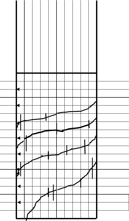
Figure 3.17. Product curves and narrow range components.

THE ATMOSPHERIC AND VACUUM CRUDE DISTILLATION UNITS 151
Table 3.2. Cut characteristics
Component %vol on crude SG @ 60
◦
F Wt factor Mol wt Mol factor
Overheads cut from gas to 375
◦
F TBP cut point (25 vol% on crude)
C2 0.11 0.374 0.411 30 0.014
C3 0.84 0.508 4.267 44 0.1
Ic4 0.40 0.563 2.252 58 0.039
nC4 1.53 0.584 8.935 58 0.154
C5’s 3.02 0.629 18.996 72 0.264
C6 3.60 0.675 24.300 86 0.286
C7 4.50 0.721 32.445 100 0.324
Comp 1 3.50 0.743 26.005 114 0.228
2 3.77 0.765 28.841 126 0.229
3 2.41 0.776 18.702 136 0.138
4 1.32 0.788 10.402 152 0.068
TOTAL 25.0 0.702 175.556 95.2 1.884
Kerosene cut range 375–480
◦
F (10 %vol on crude)
2 4.0 0.765 30.6 126 0.24
3 14.0 0.776 108.64 136 0.80
4 22.0 0.788 173.36 152 1.14
5 24.0 0.799 191.76 165 1.16
6 21.0 0.810 170.10 177 0.96
7 13.0 0.825 107.25 190 0.56
8 2.0 0.839 16.78 205 0.08
TOTAL 100.0 0.798 798.49 161.6 4.94
Light gas oil cut range 480–610
◦
F (12 %vol on crude)
6 2.0 0.810 16.2 177 0.09
7 9.0 0.825 74.25 190 0.39
8 38.5 0.839 323.02 205 1.58
9 40.5 0.848 343.44 238 1.51
10 10.0 0.860 86.00 250 0.34
TOTAL 100.0 0.843 842.91 215.6 3.91
Heavy gas oil cut range 610–680
◦
F (7.0 %vol on crude)
9 6.0 0.848 50.88 228 0.22
10 33.0 0.860 283.80 250 1.14
11 61.0 0.887 540.77 287 1.88
TOTAL 100.0 0.875 875.45 270.2 3.24
Neglect the pressure drop for fittings and piping—this will be quite small for a properly
designed unit.
Then total tower top pressure is 12 psig.
Assume 40 valve trays in the section of the tower between flash zone and tower top.
Let the pressure drop per tray be 0.25 psi. Then pressure drop in this section of the
tower is 10 psi.

152 CHAPTER 3
Table 3.3. The material balance
Cut Cum
Stream range %vol %vol BPSD GPH SG #/Gal lbs/hr %wt Mol wt Mol/hr
Whole – 100.0 100.0 30,000 52,500 0.8685 7.23 379,575 100.0 225.3 1,684.8
crude
O/head IBP 25.0 25.0 7,500 13,125 0.702 5.84 76,650 20.2 95.2 805.1
−360
Kero −480 10.0 35.0 3,000 5,250 0.798 6.64 34,860 9.2 161.6 215.7
LGO −610 12.0 47.0 3,600 6,300 0.843 7.02 44,226 11.7 215.6 205.1
HGO −690 7.0 54.0 2,100 3,675 0.875 7.28 26,754 7.0 270.2 99.0
Resid +690 46.0 100.0 13,800 24,150 0.957 8.16 197,085 51.9 547.6 359.9
The flash zone material balance
O/flash −725 3.0 57.0 900 1,575 0.891 7.4 11,655 3.0 295 39.5
Prod
vapor
−690 54.0 54.0 16,200 28,350 0.773 6.43 182,490 48.1 137.7 1,324.9
Total
vap
−725 57.0 57.0 17,100 29,925 0.780 6.49 194,145 51.1 142.3 1,364.4
Resid* +725 43.0 43.0 12,900 22,575 0.988 8.22 185,430 48.9 578.7 320.4
Total 100.0 100.0 30,000 52,500 0.8685 7.23 379,575 100.0 225.3 1,684.8
∗
Does not include liquid overflow from bottom wash tray.
Total flash zone pressure is 12 psig + 10 psi = 22 psig. Call it 25 psig (40 psia) for
design purposes.
Calculate the partial pressure of the hydrocarbon vapor at the flash zone
Take the quantity of stripping steam as 1.2 lbs/gal of residue (from Figure 3.10).
The lbs/hr of stripping steam is 1.2 × 24,150 = 28,980 lbs/hr.
= 1,610 moles/hr
The partial pressure of the hydrocarbon vapor therefore is:
Moles HC vapor
Total moles vapor
× Total pressure =
1,364.4
1,364.4 + 1,610
× 40 psia = 18.35 psia.
Calculate the EFV curve of whole crude at atmospheric pressure
From the crude TBP curve, the slope of the whole curve is 11.8
◦
F/%vol (10–70 %vol
on TBP temperatures divided by 60). From the Maxwell curves the slope of the flash
reference line slope is 8.5
◦
F/%vol. (See Chapter 1 of this Handbook.)
T
50%
(DRL − FRL) = 40
◦
F
T
50%
DRL = 667
◦
F
Then T
50%
FRL = 667 − 40 = 627
◦
F

THE ATMOSPHERIC AND VACUUM CRUDE DISTILLATION UNITS 153
Table 3.4. Flash curve at atmospheric pressure
TBP EFV
%vol Curve,
◦
F DRL T Ratio T
1
FRL Flash,
◦
F
0 −127 75 −202 0.24 −48 200 152
10 190 190 0 0.4 0 285 285
30 420 430 −10 0.34 −3 450 447
50 645 667 −22 0.34 −8 627 619
70 900 900 0 0.34 0 795 795
90 1,235 1,140 95 0.34 32 915 947
100 2,192 1,250 942 o.34 320 1,040 1,360
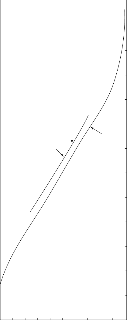
Table 3.4 defines the flash curve at atmospheric pressure.
The flash curve calculated above is that at atmospheric pressure. To plot this at any
other pressure take the 50 %vol temperature, and using the vapor pressure curves
for hydrocarbons (see Figure 1.A.1 in the appendix) read off the temperature at the
desired pressure. Draw the EFV curve through this new temperature parallel to the
atmospheric curve. The flash zone temperature is the temperature at the % distilled
on the partial pressure curve.
Flash zone temperature = 720
◦
F
The EFV curve is shown in Figure 3.18.
Calculate total heat in the crude at the flash zone conditions
See Table 3.5 for the calculation of total heat in the crude at the flash zone conditions.
Please note: The enthalpy data used here are taken from the author’s private files. It
is recommended that the data given in Maxwell’s Hydrocarbon Data or The GPSA
Engineering Data Book be used for these heat balance calculations.
The tower heat balances
To calculate the temperature of the residue product leaving the tower
Consider the heat balance over the residue stripper as shown by the envelope in Fig-
ure 3.1.11. The product residue is 197,085 lbs/hr (from the material balance). The
strip out vapor from the top stripping tray is 6% (from Figure 3.10) = 1,449 gals/hr.
Assume the SG of the strip out is 7.5 lbs/gal (about the same as the overflash) and the
mol wt is 305. Then the heat balance can be written as follows (see also Table 3.6):
Heat in = Heat out
197,085x + 45,404,000 = 119,916,000
x = 378 Btu/lb
EFV
@
29.67 Psia
EFV @
Atmos Press
Flash Zone
Temp
1100
1000
900
800
700
600
500
Temp °F
400
300
200
100
01020304050
% Vol
60 70 80 90 100
Figure 3.18. EFV curve for whole crude at flash zone conditions.

THE ATMOSPHERIC AND VACUUM CRUDE DISTILLATION UNITS 155
Table 3.5. Calculation of total heat in the crude at the flash zone conditions
Stream V/L
◦
API K
◦
F Weight, lbs/hr Btu/lb mmBtu/hr
Crude vapor V 5.0 11.8 720 194,145 528 102.509
Crude liquid L 11.5 11.5 720 185,430 396 73.43
Total 379,575 175.939
From enthalpy tables this equates to 704
◦
F.
To calculate the side stream draw-off temperatures
The steam rates to be used for side stream stripping will be:
All strippers will have three theoretical trays.
Both gas oil streams will use 0.5 lbs/gal respectively.
The Kero stripper will use 0.65 lbs/gal of steam.
Steam used is as follows:
Heavy gas oil = 3,675 × 0.5 = 1,838 lbs/hr
Light gas oil = 6,300 × 0.5 = 3,150 lbs/hr
Kero = 5,250 × 0.65 = 3,413 lbs/hr
r
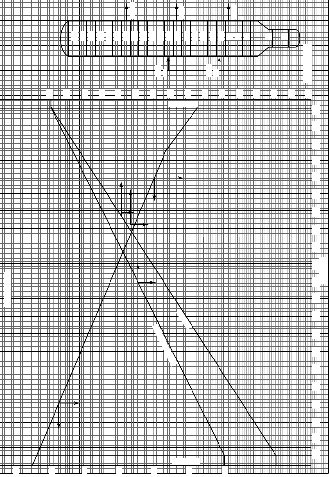
Tower pressure profile.
There will be 40 fractionating trays in the main tower (trays above the flash zone)
and four residue stripping trays (trays below the flash zone). These trays will be
numbered from the bottom to the top. Thus, the bottom residue stripping tray will
be tray 1. The tower top tray will be tray 45. The pressure profile is shown in Fig-
ure 3.1.19.
Table 3.6.
Enthalpy
Temp, Weight,
Stream V/L
◦
API K
◦
F lbs/hr Btu/lb mmBtu/hr
IN
Residue L 13 11.5 720 197,085 396 78.046
Stripout L 25.5 11.5 720 10,868 410 4.456
Steam V 450 28,980 1,290 37.384
Total in 236,923 119.916
OUT
Residue L 13 11.5 t 197,085 x 197,085x
Stripout V 25.5 11.5 715 10,868 490 5.325
Steam V 715 28,980 1,383* 40.079
Total out 236,933 45.404 + 197,085x
∗
At partial pressure of the flash zone = 13.53 psig.
25
45
43
41
39
37
35
33
KERO
LGO
BOT
PA
TOP
PA
HGO
31
29
27
25
23
21
19
17
15
13
11
9
7
5
4
1
24
23
22
21
20
19
18
17
16
15
14
13
12
11
10
579111315171921232527293133353739414345
Tray N°
Flash Zone
Press Psig
800
700
600
500
400
300
200
Tow e r To p
Tower Profile
Corrected Profile
1st Trial
Figure 3.19. Tower pressure profile.

THE ATMOSPHERIC AND VACUUM CRUDE DISTILLATION UNITS 157
r
Establish draw-off tray location
Allow six wash trays above the flash zone to the HGO draw off. The HGO and
bottom pumparound will be drawn from tray 10.
Allow two trays for the pumparound return. Thus the pumparound will return on to
tray 12.
Allow 10 trays from tray 12 to the LGO and the top pumparound draw off. The
draw-off tray will then be tray 22.
Again allow two trays for the pumparound return. This will be tray 24.
Allow 10 trays between top pumparound return and the Kero draw off. This locates
the Kero draw-off at tray 34. It leaves 12 trays between the Kero draw off and the
top tray (includes the draw-off tray and the top tray).
r
Summary of tray locations and total pressure (1st trial).
Tray no. Pressure (psig.)
HGO draw off 10 23.4
BPA return 12 22.7
LGO draw off 22 19.5
TPA return 24 18.8
Kero draw off 34 15.5
r
Calculate theoretical initial boiling points
The FRL for each cut is developed from the TBP cut. Thus:
HGO 50% TBP is 648
◦
F. Slope of TBP is 0.6
◦
F/%vol.
Slope of FRL is 0.2
◦
F/%. t50 (DRL – FRL) is 7
◦
F.
50% FRL is 641
◦
F. From FRL curve IBP is 626
◦
F.
LGO This is developed in the same manner as HGO and
the IBP of the FRL in this case is 527
◦
F.
Kero In the same way the Kero FRL has an IBP of 395
◦
F.
Now all these temperatures are at atmospheric pressure. It is now required to relate
these temperatures to the partial pressure of the respective trays.
r
To calculate the approximate partial pressures and draw-off temperatures
Assumptions:
1.0 All vapor lighter than the product cut is considered inert.
2.0 Internal reflux is assumed as follows:
To HGO tray 290 mol/hr.
To LGO tray 250 mol/hr
To Kero tray 200 mol/hr

158 CHAPTER 3
HGO tray partial pressure =
Moles of HGO
Total moles HC vapor + Steam
× Total pressure
=
1, 614.9
3, 224.9
× 38.1 = 19.6 psia
From vapor pressure curves theoretical draw-off temperature is 720
◦
F.
From Figure 3.9:
Theoretical temperature − Actual temperature = 93
◦
F
Actual draw-off temperature is 720 −93 = 627
◦
F
Draw-off temperatures for the LGO and Kero are calculated in the same way and are:
LGO = 493
◦
F
Kero = 364
◦
F.
To calculate the tower top temperature
Set the reflux drum temperature and pressure. In this case these will be set at 10 psig
and 100
◦
F. Taking the pressure drop across the exchangers and piping the tower top
pressure will be 15 psig.
Fix the cold external reflux at 0.8 times the total moles overhead product;
The total moles HC in the overhead vapor is 1.8 × 805.1 = 1,449.18 moles/hr
Total moles steam in the overhead vapor is 2,076
Partial pressure of the hydrocarbons in the overhead vapor is:
1,449.19 × 29.7
3,525.18
= 12.2 psia
The tower overhead temperature is the dew point of the hydrocarbons at the partial
pressure and is shown in Table 3.7.
K
2
= K
1
× Sx = 0.135 × 0.984 = 0.133 = 246
◦
F which will be the tower top tem-
perature.
To calculate side stream stripper bottom temperatures
These are calculated by heat balances over the respective side stream strippers. The
following criteria are used in these calculations:

THE ATMOSPHERIC AND VACUUM CRUDE DISTILLATION UNITS 159
Table 3.7.
1st trial @ 250
◦
F Weight Volume
Comp Mol frac KX= y/K Mol wt factor SG @ 60 factor
C2 0.008 Neg Nil
C3 0.054 73.77 0.001 44 0.044 0.508 0.009
iC4 0.021 35.24 0.001 58 0.058 0.563 0.010
nC4 0.084 27.05 0.003 58 0.174 0.584 0.030
C5 0.143 11.80 0.012 72 0.864 0.629 0.137
C6 0.155 4.590 0.034 85 2.89 0.675 0.428
C7 0.175 2.213 0.079 100 7.90 0.721 1.100
Comp 1 0.124 1.066 0.116 114 13.224 0.743 1.780
Comp 2 0.124 0.557 0.223 126 28.098 0.765 3.673
Comp 3 0.075 0.311 0.241 136 32.776 0.776 4.224
Comp 4 0.037 0.135 0.274 152 41.648 0.788 5.285
Total 1.000 0.984 129.7 127.676 0.766 16.675
HGO LGO KERO
Total strip out % vol 5 8 8
Mol wt of strip out 230 180 120
SG of strip out 0.865 0.820 0.750
Only the heat balance calculation of the HGO stripper is given below (see also Table
3.8). The other two stripper calculations will be similar in form (Figures 3.20–3.22).
Solving for x: 26,754x = 8,997,000
x = 336 Btu/lb
From enthalpy tables = 615
◦
F
Table 3.8.
Stream V/L
◦
API K
◦
F lbs/hr Btu/lb mmBtu/hr
In
Feed ex Hgo L 30 11.5 627 26,754 347 9.284
Steam V – – 450 1,838 1,290 2.371
Strip out L 32 11.5 627 1,390 349 0.485
Total In 29,982 12.14
Out
Hgo L 30 11.5 t
◦
F 26,754 x 26,754x
Steam V 622 1,838 1,376* 2.529
Strip out V 32 11.5 622 1,390 442 0.614
Total out 29,982 3.143 + 26,754x
*At partial pressure of 36.3 psia.