John Campbell. Castings Practice:The Ten Rules of Castings.2004
Подождите немного. Документ загружается.

extremely effective in absorbing the energy of
the flow. In this respect its action resembles that
of a ceramic foam filter. To enable the device to
be used in routine casting production the energy
absorbing behaviour would require to be
quantified. There is no shortage of future tasks.
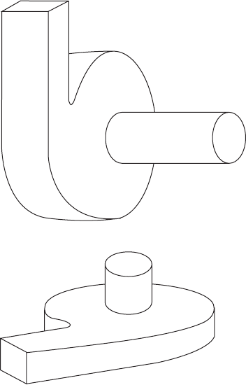
Vortex runner (the offset sprue)
The simple provision of an offset sprue causes
the runner to fill tangentially, the melt spinning
at high speed (Figures 2.19e and 2.45). The
technique is especially suited to a vertically
parted mould, where a rectangular cross-section
sprue, moulded on only one side of the parting
line, opens into a cylindrical runner moulded on
the joint. The consequential highly organized
filling of the runner is a definite improvement
over many poor runner designs, as has been
demonstrated by the Weibull statistics of
strengths of castings produced by conventional
in-line and offset (vortex) runners (Yang et al.
1998, 2000 and 2003). The technique produces
convincingly more reliable castings than con-
ventional in-line sprues and runner systems.
However, at this time it is not certain that the
action of the vortex runner is better than other
useful solutions such as the slot sprue/slot run-
ner, or the vortex well, but it has the great
benefit of simplicity. It promises to be valuable
for vertically parted moulds; it deals effectively
with the problem of high flow velocities in such
moulds because of the great fall heights often
encountered.
2.3.3 Horizontal transfer casting
The quest to avoid the gravity pouring of liquid
metals has led to systems employing horizontal
transfer and counter-gravity transfer. These
solutions to avoid pouring are clearly seen to be
key developments; both seem capable of giving
competitive casting processes that offer products
of unexcelled quality. The two major approaches
to the first approach, horizontal transfer, are
described below.
2.3.3.1 Level pour (side pour)
The `level pour' technique was invented by Erik
Laid (1978). At that time this clever technique
delivered castings of unexcelled quality. It seems
a pity that the process is not more generally
used. This has partly occurred as the result of
the process remaining commercially confidential
for much of its history, so that relatively little
has been published concerning the operational
details that might assist a new user to achieve
success. Also, the technique is limited to the type
of castings, being applied easily only to plate,
box or cylinder type castings where a long slot
ingate can be provided up the complete height of
the casting. In addition, of course, a fairly
complex casting station is required.
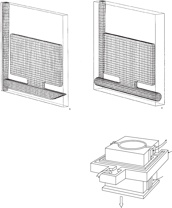
The arrangement to achieve the so-called
level filling of the mould is shown in Figure 2.46.
An insulated pouring basin connects to a hori-
zontal insulated trough that surrounds three of
the four sides of the mould (a distribution sys-
tem reminiscent of a Roman aqueduct). The
melt enters the mould cavity via slot gates that
extend vertically from the drag to the cope.
Either side of each slot gate are guide plates that
contain the melt between sliding seals as it flows
out of the (stationary) trough and into the
(descending) mould.
Casting starts with the mould sitting on the
fully raised mould platform, so that the trough
provides its first metal at the lowest level of the
drag. The mould platform is then slowly low-
ered while pouring continues. The rate of with-
drawal of the mould is such that the metal in
the slot gate has time to solidify prior to its
Figure 2.44 (a) Vortex well (with horizontal axis)
and (b) vortex gate (with vertical axis).
68 Castings Practice: The 10 Rules of Castings
(a)
(b)
appearance as it slides out below the level of the
trough.
In one of the rare descriptions of the use of the
process by Bossing (1982) the large area of melt
contained in the pouring basin and distribution
trough would materially help to smooth the
rate of flow from the point of pour to delivery
into the mould. Also in this description is
an additional complicated distribution system
inside the mould, in which tiers of runners are
provided to minimize feeding distances and
maximize temperature gradients. In general, such
sophistication would not be expected to be
necessary for most products.
2.3.3.2 Controlled tilt casting
It seems that foundrymen have been fascinated
by the intuition that tilt casting might be a
solution to the obvious problems of gravity
pouring. The result has been that the patent
literature is littered with re-inventions of the
process decade after decade.
Even so, the deceptive simplicity of the pro-
cess conceals some fundamental pitfalls for the
unwary. The piles of scrap seen from time to
time in tilt-pour foundries are silent testimony
to these hidden dangers. Generally, however,
the dangers can be avoided, as will be discussed
in this section.
Tilt casting is a process with the unique fea-
ture that, in principle, liquid metal can be
transferred into a mould by simple mechanical
means under the action of gravity, but without
surface turbulence. It therefore has the potential
to produce very high quality castings. This was
understood by Durville in France in the 1800s
and applied by him for the casting of aluminium-
bronze in an effort to reduce surface defects in
French coinage.
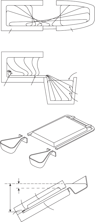
The various stages of liquid metal transfer
in the Durville Process are schematically
illustrated in Figure 2.47a. In the process as
Figure 2.45 (a) A conventional runner, and (b) a vortex runner, useful on a vertically parted mould (courtesy of X. Yang
and Flow 3-D).
Figure 2.46 Level pour technique.
Rule 2. Avoid turbulent entrainment 69
(a) (b)
Insulated
guide
plates
Insulated
distributio
n
trough
Frozen ingate
Mould platform (incorporating mould
clamping + lifting features)
lowered by electric motor drive
Mould
Liquid
metal
poured
from insulated
ladle
Core
originally conceived by Durville, the metal is
melted in the same crucible as is used for the tilt
machine. No pouring under gravity takes place at
all. Also, since he was casting large, open-ended
ingots for subsequent working, he was able to
look into the crucible and into the mould,
observing the transfer of the melt as the rotation
of the mould progressed. In this way he could
ensure that the rate of rotation was correct to
avoid any disturbance of the surface of the
liquid. During the whole process of the transfer,
careful control ensured that the melt progressed
by `rolling' in its skin of oxide, like inside a
rubber sack, avoiding any folding of its skin by
disturbances such as waves. The most sensitive
part of the transfer was at the tilt angle close to
the horizontal. In this condition the melt front
progresses by expanding its skin of oxide, while
its top surface at all times remains horizontal
and tranquil.
In the USA, Stahl (1961) popularized the
concept of `tilt pouring' for aluminium alloys
into shaped permanent mould castings. The
gating designs and the advantages of tilt pouring
over gravity top pouring have been reviewed
and summarized in several papers from this
source (Stahl 1963, 1986, 1989).
A useful `bottom-gated' tilt arrangement is
shown in 2.47c, d. Here the sprue is in the drag,
and the remainder of the running and gating
system, and the mould cavity, is in the cope.
Care needs to be taken with a tilt die to ensure
that the remaining pockets of air in the die can
vent freely to atmosphere. Also, the die side that
retains the casting has to contain the ejectors if
they are needed. The layout in Figure 2.47c illus-
trates a unique benefit enjoyed by tilt casting:
a single operator can fill both pouring cups from
a large ladle prior to starting the tilt. Static
gravity casting would require two pourers to fill
two pouring basins.
In an effort to understand the process in
some depth, Nguyen and Carrig (1986) simu-
lated tilt casting using a water model of liquid
metal flow, and Kim and Hong (1995) carried
out some of the first computer simulations of
the tilt casting process. They found that a
combination of gravity, centrifugal and Coriolis
forces govern tilt-driven flow. However, for the
slow rates of rotation such as are used in most
tilt casting operations, centrifugal and Coriolis
effects contribute less than 10 per cent of the
effects due to gravitational forces, and could
therefore normally be neglected. The angular
velocity of the rotating mould also made some
contribution to the linear velocity of the liquid
front, but this again was usually negligible
because the axis of rotation was often not far
from the centre of the mould.
However, despite these studies, and despite
its evident potential, the process has continued
to be perfectly capable of producing copious
volumes of scrap castings.
Figure 2.47 Tilt casting process (a) Durville;
(b) Semi-Durville; (c) twin-poured tilting die (adapted
from Nyamekye et al. 1994); and (d) outline of tilt
running system design at the critical moment that metal
reaches the far end of the `sprue'.
70 Castings Practice: The 10 Rules of Castings
Mould
Melting crucible
(a)
(b)
Metal level
too low
Metal on
brink of pour
Metal starts
pour at steep
angle of tilt
Persistent
oxide
flow
tube
Initial
surface
turbulence
(c)
h
1
h
2
(d)
Casting
Ingate
Cross
runner
Down-runner
or sprue
The first detailed study of tilt casting using
the recently introduced concepts of critical
velocity and surface turbulence was carried
out in the author's laboratory by Mi (2002).
In addition to the benefits of working within
the new conceptual framework, he had avail-
able powerful experimental techniques. He
used a computer controlled, programmable
casting wheel onto which sand moulds could be
fixed to produce castings in an Al±4.5%Cu
alloy. The flow of the metal during the filling
of the mould was recorded using video X-ray
radiography, and the consequential reliability
of the castings was checked by Weibull
statistics.
Armed with these techniques, Mi found that
at the slow rotation speeds used in his work the
mechanical effect of surface tension and/or
surface films on the liquid meniscus could not be
neglected. For all starting conditions, the flow
at low tilt speeds is significantly affected by
surface tension (most probably aided by the
effect of a strong oxide film). Thus below a
speed of rotation of approximately 7 degrees per
second the speed of the melt arriving at the end
of the runner is held back. Gravity only takes
control after tilting through a sufficiently large
angle.
As with most casting processes, if carried out
too slowly, premature freezing will lead to mis-
run castings. One interesting case was found
in which the melt was transferred so slowly into
the runner that frozen metal in the mouth
of the runner acted as an obstructing ski jump
to the remaining flow, significantly impairing
the casting. At higher speeds, however, although
ski jumps could be avoided, the considerable
danger of surface turbulence increased.
The radiographic recordings revealed that
the molten metal could exhibit tranquil or
chaotic flow into the mould during tilt casting,
depending on (i) the angle of tilt of the mould at
the start of casting, and (ii) the tilting speed. The
quality of the castings (assessed by the scatter in
mechanical properties) could be linked directly
to the quality of the flow into the mould.
We can follow the progress of the melt during
the tilt casting process. Initially, the pouring
basin at the mouth of the runner is filled. Only
then is the tilting of the mould activated. Three
starting positions were investigated:
(i) If the mould starts from some position in
which it is already tilted downward, once
the metal enters the sprue it is immediately
unstable, and runs downhill. The melt
accelerates under gravity, hitting the far
end of the runner at a speed sufficient to
cause splashing. The splash action entrains
the melt surface. Castings of poor reliability
are the result.
(ii) If the mould starts from a horizontal posi-
tion, the metal in the basin is not usually
filled to the brim, and therefore does not
start to overflow the brim of the basin and
enter the runner until a finite tilt angle has
been reached. At this stage the vertical fall
distance between the start and the far end of
the runner is likely to be greater than the
critical fall distance. Thus although slightly
better castings can be made, the danger
of poor reliability remains. This unsatisfac-
tory mode of transfer typifies many tilt
casting arrangements, particularly the so-
called Semi-Durville type process shown in
Figure 2.47b.
(iii) If, however, the mould is initially tilted
slightly uphill during the filling of the basin,
there is a chance that by the time the change
of angle becomes sufficient to start the
overflow of melt from the basin, the angle
of the runner is still somewhat above the
horizontal. The nature of the liquid metal
transfer is now quite different. At the start
of the filling of the runner the meniscus is
effectively climbing a slight upward slope.
Thus its progress is totally stable, its
forward motion being controlled by addi-
tional tilt. If the mould is not tilted further
the melt will not advance. By extremely
careful control of the rate of tilt it is possible
in principle to cause the melt to arrive at the
base of the runner at zero velocity if
required. (Such drastic reductions in speed
would, of course, more than likely be
counter-productive, involving too great a
loss of heat, and are therefore not recom-
mended.) Even at quite high tilting speeds
of 30 degrees per second as used by Mi in his
experimental mould, the velocity of the melt
at the end of the runner did not exceed the
critical value 0.5 m s
ÿ1
, and thus produced
sound and repeatable castings.
The unique feature of the transfer when started
above the horizontal in this way (mode iii
above) is that the surface of the liquid metal is
close to horizontal at all times during the
transfer process. Thus in contrast to all other
types of gravity pouring, this condition of tilt
casting does not involve pouring (i.e. a free
vertical fall) at all. It is a horizontal transfer
process. It will be seen that in the critical region
of tilt near to the horizontal, the nature of the
transfer is the same as that employed originally
by Durville.
Thus the optimum operational mode for tilt
casting is the condition of horizontal transfer.
Rule 2. Avoid turbulent entrainment 71
Horizontal transfer requires the correct choice
of starting angle above the horizontal, and the
correct tilting speed.
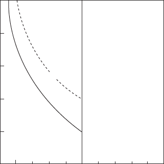
An operational map was constructed
(Figure 2.48), revealing for the first time a
window for the production of reliable castings.
It is recognized that the conditions defined by
the window are to some extent dependent on the
geometry of the mould that is chosen. However,
the mould in Mi's experiments was designed to
be close to the size and shape of many industrial
castings, particularly those for automotive
applications. Thus although the numerical con-
clusions would require some adaptation for
other geometries, the principles are of general
significance and are clear: there are conditions,
possibly narrowly restricted, but in which hor-
izontal transfer of the melt is possible, and gives
excellent castings.
The problem of horizontal transfer is that it is
slow, sometimes resulting in the freezing of the
`ski jump' at the entrance to the runner, or even
the non-filling of the mould. This can usually be
solved by increasing the rate of tilt after the
runner is primed. This is the reason for the
extended threshold, denoted a marginal filling
condition, on the left of the window shown on
the process map (Figure 2.48). A constant tilt
rate (as is common for most tilt machines at this
time) cannot achieve this useful extension of the
filling conditions to achieve good castings.
Programmable tilt rates are required to achieve
this solution.
A final danger should be mentioned. At cer-
tain critical rates of rise of the melt against an
inclined surface, the development of the trans-
verse travelling waves seems to occur to give lap
problems on the cope surface of castings (illu-
strated later in Figure 2.60). In principle, such
problems could be included as an additional
threshold to be avoided on the operational
window map (Figure 2.48). Fortunately, this
does not seem to be a common fault. Thus in the
meantime, the laps can probably be avoided by
increasing the rate of tilt during this part of the
filling of the mould. Once again, the benefits of
a programmable tilt rate are clear.
Insummary,the conclusions fortiltcastingare:
1. If tilt casting is initiated from a tilt orienta-
tion at, or (even more especially) below the
horizontal, during the priming of the runner
the liquid metal runs downhill at a rate out of
the control of the operator. The accelerating
stream runs as a narrow jet, forming a
persistent oxide flow tube. In addition, the
velocity of the liquid at the far end of the
runner is almost certain to exceed the critical
condition for surface turbulence. Once the
mould is initially inclined by more than
10 degrees below the horizontal at the
initiation of flow, Mi found that it was no
longer possible to produce reliable castings
by the tilt casting process.
2. Tilt casting operations benefit from using a
sufficiently positive starting angle that the
melt advances into an upward sloping run-
ner. In this way its advance is stable and
controlled. This mode of filling is character-
ized by horizontal liquid metal transfer,
promoting a mould filling condition free
from surface turbulence.
3. Tilt filling is preferably slow at the early
stages of filling to avoid the high velocities at
the far end of the running system. However,
after the running system is primed, speeding
up the rate of rotation of the mould greatly
helps to prevent any consequential non-
filling of the castings.
2.3.4 Counter-gravity
There are some advantages to the use of gravity
to action the filling of moulds. It is simple, low
cost and completely reliable, since gravity has
never been known to suffer a power failure. It is
with regret, however, that the advantages finish
here, and the disadvantages start. Furthermore,
the disadvantages are serious.
Nearly all the problems of gravity pouring
arise as a result of the velocity of the fall. After a
trivial fall distance corresponding to the critical
fall height, gravity has accelerated the melt to its
critical velocity. Beyond this point there is the
Figure 2.48 Map of variables for tilt pouring, showing
the operational window for good castings (Mi et al. 2002).
72 Castings Practice: The 10 Rules of Castings
–20
0 0.5
Maximum velocity of
metal front in runner (m s
–1
)
10
–10
0
10
20
30
Reliable, filled
castings
Incomplete
filling
Initial angle of mould (degrees above horizontal)
Unreliable
castings
Marginal
filling
danger of entrainment defects. Because the
critical fall distance is so small, being only the
height of a sessile drop of the liquid, nearly all
actual falls exceed this limit. In other words the
energy content of the melt, when allowed to fall
even only relatively small distances under grav-
ity, is nearly always sufficiently high to lead to the
break-up of the liquid surface. (It is of little
comfort at this time to know that foundries on
the moon would fare better.)
A second fundamental drawback of gravity
filling is the fact that at the start of pouring, at
the time the melt is first entering the ingates, the
narrowest part of the mould cross-section where
volume flow rate should be slowest, the speed of
flow by gravity is highest. Conversely, at a late
stage of filling, when the melt is at its coldest
and approaching the top of the mould cavity,
and the melt needs to be fastest, the speed of
filling is slowest. Thus filling by gravity gives
completely the wrong filling profile.
Thus to some extent, there are always prob-
lems to be expected with castings poured by
gravity. The long section on filling system
design in this book is all about reducing this
damage as far as possible. It is a tribute to the
dogged determination of the casting fraternity
that gravity pouring, despite its severe short-
comings, has achieved the level of success that it
currently enjoys.
Even so, over the last 100 years and more, the
fundamental problems of gravity filling have
prompted casting engineers to dream up and
develop counter-gravity systems.
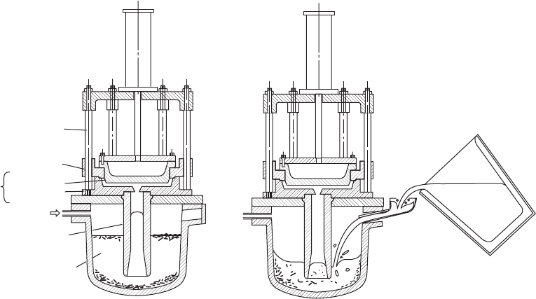
Numerous systems have arisen. The most
common is low-pressure casting, in which air or
an inert gas is used to pressurize an enclosed
furnace, forcing the melt up a riser tube and into
the casting (Figure 2.49). Other systems use a
partial vacuum to draw up the metal. Yet others
use various forms of pumps, including direct
displacement by a piston, by gas pressure
(pneumatic pumps), and by various types of
electromagnetic action.
Clearly, with a good counter-gravity system,
one can envisage the filling of the mould at
velocities that never exceed the critical velocity,
so that the air in the mould is pushed ahead of
the metal, and no surface entrainment occurs.
The filling can start gently through the ingates,
speed up during the filling of the main part of
the mould cavity, and finally slow down and
stop as the mould is filled. The final deceleration
is useful to avoid any final impact at the instant
the mould is filled. If not controlled in this way,
the transient pressure pulse resulting from the
sudden loss of momentum of the melt can cause
the liquid to penetrate any sand cores, open
mould joints to produce flash, and generally
impair surface finish.
When using a good counter-gravity system,
good filling conditions are not difficult to
achieve. In fact, in comparison with gravity
pouring where it is sometimes difficult to achieve
a good casting, counter-gravity is such a robust
technique that it is often difficult to make a bad
casting. This fundamental difference between
gravity and counter-gravity filling is not widely
Figure 2.49 (a) Low-pressure casting process, and (b) the usual poor filling technique.
Rule 2. Avoid turbulent entrainment 73
(a) (b)
Air cylinder
to open die
Gulde bars
Ejector
Gas pressure
Riser tube
Melt with
accumulated
oxides
Die
set
Top die
Bottom die
appreciated. In general, only those who have
suffered gravity filling and finally accepted
counter-gravity appreciate and are amazed by
the powerful benefits.
That is not to say that the technique is not
sometimes used badly. The usual failure is to
keep the metal velocity under control. However,
in principle it can be controlled, in contrast to
gravity pouring where, in principle, control is
often difficult or impossible.
A concern often expressed about counter-
gravity is that the adoption of filling speeds
below the critical speed of approximately
0.5 m s
ÿ1
will slow the production rate. Such
fears are groundless. For instance if the casting
is 0.5 m tall (a tall casting) it can, in principle, be
filled in one second. This would be a challenge!
In fact the unfounded fear of the use of low
velocities of the melt leading to a sacrifice of
production rate follows from the confusion of
(i) flow velocity (usually measured in m s
ÿ1
) and
(ii) melt volume flow rate (usually measured
in m
3
s
ÿ1
). For instance the filling time can be
kept short by retaining a slow filling velocity
but increasing the volume flow rate simply by
increasing the areas of the flow channels.
Worked examples to emphasize and clarify this
point further will be given in Section 2.3.7
dealing with the calculation of the filling system.
2.3.4.1 Programmable control
The varying cross-sectional areas of the metal as
it rises in the mould pose a problem if the fill
rate through the bottom gate is fixed (as is
approximately true for many counter-gravity
filling systems that lack any sophistication of
programmable control). Naturally, the melt
may become too slow if the area of the mould
increases greatly, leading to a danger of cold
laps or oxide laps. Alternatively, if the local
velocity is increased above the critical velocity
through a narrow part of the mould, the metal
may jet, causing entrainment defects.
Counter-gravity filling is unique in having
the potential to address this difficulty. In prin-
ciple, the melt can be speeded up or slowed
down as required at each stage of filling. Even
so, such programming of the fill rate is not easily
achieved. In most moulds there is no way to
determine where the melt level is at any time
during filling. Thus if the pre-programmed fill-
ing sequence (called here the filling profile) gets
out of step, its phases occurring either early or
late, the filling can become worse than that
offered by a constant rate system. The mis-
timing problems can easily arise from splashes
that happen to start timers early, or from
blockage in the melt delivery system causing the
time of arrival of the melt to be late.
2.3.4.2 Feedback control
The only sure way to avoid such difficulties is to
provide feedback control. This involves a sys-
tem to monitor the height of metal in the mould,
and to feed this signal back to the delivery sys-
tem, to force the system to adhere to a pre-
programmed fill pattern.
One system for the monitoring of height is
the sensing of the pressure of the melt in the melt
delivery system. This has been attempted by the
provision of a pocket of inert gas above the melt
contained in the permanent plumbing of the
liquid metal delivery system, and connected to a
pressure transducer via a capillary.
A non-contact system used by the Cosworth
sand casting process senses the change in capa-
citance between the melt and the mould clamp
plate when the two are connected as a parallel
plate condenser. Good feedback control solves
many of the filling problems associated with
casting production.
However, elsewhere, feedback control is little
used at this time. The lack of proper control in
counter-gravity leads to unsatisfactory modes of
filling that explain some of the problems with
the technique. The other problems relate to the
remainder of the melting and melt handling
systems in the foundry, that are often poor,
involving multiple pouring operations from melt
furnaces to ladles and then into the counter-
gravity holding vessel. A widespread re-charging
technique for a low-pressure casting unit is
illustrated in Figure 2.49b; much of the
entrainment damage suffered in such processes
usually cannot be blamed on the counter-gravity
system itself. The problem arises earlier because
of inappropriate metal handling in the foundry
before any casting takes place.
The lesson is that only limited success can be
expected from a foundry that has added a coun-
ter-gravity system on to the end of a badly
designed melting and melt-handling system.
There is no substitute for an integrated approach
to the whole production system. Some of the very
few systems to achieve this so far have been the
processes that the author has helped to develop;
the Cosworth Process (see description later under
Rule 7) and Alotech Processes. In these processes,
when properly implemented, the liquid metal is
never poured, never flows downhill, and is finally
transferred uphill into the mould.
Finally, the concept of an integrated approach
necessarily involves dealing with convection
during the solidification of the casting. This ser-
ious problem is usually completely overlooked.
74 Castings Practice: The 10 Rules of Castings
It has been the death of many otherwise good
counter-gravity systems, but is specifically
addressed in the Cosworth and Alotech systems.
The problem is highlighted by the author as
Rule 7.
The numerous forms of counter-gravity
techniques will be discussed in detail in Volume 3
`Casting Processes'.
2.3.5 Surface tension controlled filling
This section starts with the interesting situation
that the liquid may not be able to enter the
mould at all. This is to be expected if the pres-
sure is too low to force melt into a narrow
section. It is an effect due to surface tension. If
the liquid surface is forced to take up a sharp
curvature to enter a non-wetted mould then it
will be subject to a repulsive force that will resist
the entry of the metal. Even if the metal enters, it
will still be subject to the continuing resistance
of surface tension, which will tend to reverse the
flow of metal, causing it to empty out of the
mould if there is any reduction in the filling
pressure. These are important effects in narrow-
section moulds (i.e. thin-section castings) and
have to be taken into account.
We may usefully quantify our formulation of
this problem with the well-known equation
Pi ÿ Pe g1=r
1
1=r
2
(2.3)
where Pi, is the pressure inside the metal, and Pe
the external pressure (i.e. referring to the local
environment in the mould). The two radii r
1
and
r
2
define the curvature of the meniscus in two
planes at right angles. The equation applies to
the condition when the pressure difference
across the interface is exactly in balance with the
effective pressure due to surface tension. To
describe the situation for a circular-section tube
of radius r (where both radii are now identical),
the relation becomes:
Pi ÿ Pe 2g=r (2.4)
For the case of filling a narrow plate of thick-
ness 2r, one radius is, of course, r, but the radius
at right angles becomes infinite, so the recipro-
cal of the infinite radius equates to zero (i.e. if
there is no curvature there is no pressure dif-
ference). The relation then reduces to the effect
of only the one component of the curvature, r:
Pi ÿ Pe g=r (2.5)
We have so far assumed that the liquid metal
does not wet the mould, leading to the effect of
capillary repulsion. If the mould is wetted then
the curvature term g/r becomes negative, so
allowing surface tension to assist the metal to
enter the mould. This is, of course, the familiar
phenomenon of capillary attraction. The pores
in blotting paper attract the ink into them; the
capillary channels in the wick of a candle suck
up the molten wax; and the water is drawn up
the walls of a glass capillary. In general, how-
ever, the casting technologist attempts to avoid
the wetting of the mould by the liquid metal.
Despite all efforts to prevent it, wetting some-
times occurs, leading to the penetration of the
melt into sand cores and moulds.
Continuing now in our assumption that
the metal±mould combination is non-wetting,
we shall estimate what head of metal will be
necessary to force it into a mould to make a wall
section of thickness 2r for a gravity casting
made under normal atmospheric pressure. If the
head of liquid is h, the hydrostatic pressure at
this depth is rgh, where r is the density of
the liquid, and g the acceleration due to gravity.
The total pressure inside the metal is therefore
the sum of the head pressure and the atmo-
spheric pressure, Pa. The external pressure is
simply the pressure in the mould due to the
atmosphere Pa plus the pressure contributed by
mould gases Pm. The equation now is
Pa rgh ÿ Pa Pm > g=r (2.6)
giving immediately
rgh ÿ Pm > glr (2.7)
The back-pressure due to outgassing in the
mould lowers the effective head driving the
filling of the mould. It is good practice, there-
fore, to vent narrow sections, reducing this
resistance to practically zero if possible.
It is also clear from the above result that,
provided the mould is permeable and/or well
vented, atmospheric pressure plays no part in
helping or resisting the filling of thin sections in
air, since it acts equally on both sides of the
liquid front, cancelling any effect. Interestingly,
the same equation and reasoning applies to
casting in vacuum, which, of course, can be
regarded as casting under a reduced atmo-
spheric pressure. Clearly, a vacuum casting is
therefore not helpful in overcoming the resist-
ance to filling provided by surface tension
(although, to be fair, it may help by reducing Pm
by outgassing the mould to some extent prior to
casting, and it will help where the permeability
of the mould is low, where residual gases may be
compressed ahead of the advancing stream.
Vacuum casting may also help to fill the mould
by reducingÐbut not eliminatingÐthe effect of
the surface film of oxide or nitride).
The case of vacuum-assisted filling (not
vacuum casting) is quite different, since the
Rule 2. Avoid turbulent entrainment 75
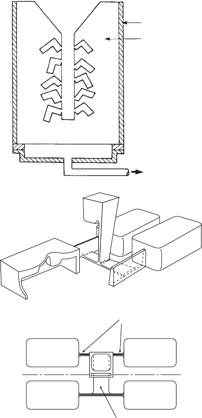
vacuum is not now applied to both the front and
back of the liquid meniscus, thus cancelling any
benefit as above, but applied only to the
advancing front as illustrated in Figure 2.50.
This application of a reduced pressure to one
side of the meniscus creates a differential
pressure that drives the flow. The differential
pressure acts by atmospheric pressure continu-
ing to apply to the liquid metal via the running
system, but the atmospheric pressure in the
mould is reduced by applying a (partial) vacuum
in the mould cavity. This is achieved by drawing
the air out either through the permeable mould,
or through fine channels cut through to the
section required to be filled (as is commonly
applied to the trailing edge of an aerofoil blade
section). In this way Pm is guaranteed to be zero
or negligible, and Pa remains a powerful pres-
sure to assist in overcoming surface tension as
the equation indicates:
Pa rgh > g=r (2.8)
It is useful to evaluate the terms of this equation
to gain a feel for the size of the effects involved.
Taking, roughly, g as 10 m s
ÿ2
, and the liquid
aluminium density r as 2500 kg m
ÿ3
and g as
1.0 N m
ÿ1
(for steels and high-temperature
alloys the corresponding values are approxi-
mately 7000 kg m
ÿ3
and 2.0 N m
ÿ1
), the resist-
ance term g/r works out to be 2 kPa for a 1 mm
section (0.5 mm radius) and 10 kPa for a 0.1 mm
radius trailing edge on a turbine blade.
For a head of metal h 100 mm the head
pressure rgh is 2.5 kPa, showing that the 1 mm
section might just fill. However, the 0.1 mm
trailing edge has no chance; the head pressure
being insufficient to overcome the repulsion of
surface tension. However, if vacuum assistance
were applied (NB not vacuum casting, remem-
ber) then the additional 100 kPa of atmospheric
pressure normally ensures filling. In practice it
should be noted that the full value of atmo-
spheric pressure is not easily obtained in
vacuum-assisted casting; in most cases a value
nearer half an atmosphere is more usual. Even
so, the effect is still important: one atmosphere
pressure corresponds to 4 m head of liquid alu-
minium, and approximately 1.5 m head of denser
metals such as irons, steels and high-temperature
alloys. In modest-sized castings of overall height
around 100 mm or so, these valuable pressures to
assist filling are not easily obtainable by other
means. The pressure delivered by a feeder placed
on top of the casting may only apply the addi-
tional head corresponding to its height of per-
haps 0.1 to 0.4 m; only one tenth of the pressures
that can be applied by the atmosphere.
For those castings that have sections of only
1 or 2 mm or less, the surface tension wields
strong control over the tight radius of the front.
Filling is only possible by the operation of
additional pressure, such as that provided by the
jeweller's centrifuge, or the application of
vacuum assistance. Filling can occur upwards or
downwards without problems, being always
Figure 2.50 (a) A plaster mould encased in a steel box
using vacuum-assisted filling through the base of the
mould. No formal running system is required for such
small thin-walled castings. (b) Sand mould to make four
cover castings, using narrow slot filling system to max-
imize benefits from surface tension and wall friction.
76 Castings Practice: The 10 Rules of Castings
Gates 50 × 4
tapered to 2
Runner 25 × 5
(Steel container)
(Permeable
plaster mould)
(a)
(b)
Vacuum
under the control of the surface tension, which is
effectively so strong in such thin sections that it
keeps the surface intact. Surface turbulence is
thereby suppressed. The liquid has insufficient
room to break up into drops, or to jet or splash.
The integrity of the front is under the control of
surface tension at all times. This special feature
of the filling of very thin-walled castings means
that they do not require formal running systems.
In fact, such thin-walled investment castings are
made successfully by simply attaching wax
patterns in any orientation directly to a sprue
(Figure 2.50). The metal flows similarly with
either gravity or counter to gravity, and no
`runner' or `gate' is necessary.
To gain an idea of the head of metal required
to force the liquid metal into small sections,
from Equation 2.8 we have:
rgh g=r
h g=rrg (2.8a)
Using the values for aluminium and steel given
above, we can now quickly show that to pene-
trate a 1 mm section we require heads of at least
80 and 60 mm respectively for these two liquids.
If the section is halved, the required head for
penetration is, of course, doubled. Similarly, if
the mould shape is not a flat section that
imposes only one curvature on the meniscus, but
is a circular hole of diameter 1 mm, the surface
then has an additional curvature at right angles
to the first curvature. Equation 2.4 shows the
head is doubled again.
In general, because of the difficulty of pre-
dicting the shape of the liquid surface in com-
plex and delicate castings, the author has found
that a safety factor of 2 is not excessive when
calculating the head height required to fill thin
sections. This safety factor is quickly used up
when allowances for errors in the wall thickness,
and the likely presence of surface films is taken
into account.
The resistance to flow provided by surface
tension can be put to good effect in the use of
slot-shaped filling systems. In this case the slots
are required to be a maximum thickness of only
1 or 2 (perhaps 3 at the most) mm for engi-
neering castings (although, clearly, jewellery
and other widget type products might require
even thinner filling systems). Figure 2.50b shows
a good example of such a system. A similar
filling system for a test casting designed by the
author, but using a conical basin (not part of the
author's original design!), was found to perform
tolerably well, filling without the creation of
significant defects (Groteke 2002). It is quite
evident, however, when filling is complete such
narrow filling channels offer no possibility of
significant feeding. This is an important issue
that should not be forgotten. In fact, in these
trials, this casting never received the proper
attention to feeding, and as a consequence suf-
fered surface sinks and internal microporosity
(the liquid alloy was clearly full of bifilms that
were subsequently opened by the action of
solidification shrinkage).
Finally, however, in some circumstances
there may be fundamental limitations to the
integrity of the liquid front in very thin sections.
(i) There is a little-researched effect that the
author has termed microjetting (Castings
2003). This phenomenon has been observed
during the filling of liquid Al±7Si±0.4Mg
alloy into plaster moulds of sections be-
tween 1 and 3 mm thickness (Evans et al.
1997). It seems that the oxide on such small
liquid areas temporarily restrains the flow,
but repeatedly splits open, allowing jets of
liquid to be propelled ahead of the front. The
result resembles advancing spaghetti. The
mechanical properties are impaired by
the oxide films around the jets that become
entrained in the maelstrom of progress of
the front. Whether this unwelcome effect
is common in thin-walled castings is un-
known, and the conditions for its formation
and control are also unknown. Very thin
walled castings remain to be researched.
(ii) In pressure die-castings a high velocity v of
the metal through the gate is necessary to
fill the mould before too much heat is lost to
the die. Speeds of between 25 and 50 m s
ÿ1
are common, greatly exceeding the critical
velocity of approximately 0.5 m s
ÿ1
that
represents the watershed between surface
tension control and inertial control of the
liquid surface. The result is that entrain-
ment of the surface necessarily occurs on a
huge scale. The character of the flow is now
dictated by inertial pressure, proportional
to v
2
, that vastly exceeds the restraining
influences of gravity or surface tension.
This behaviour is the underlying reason
for the use of PQ
2
diagrams as an attempt to
understand the filling of pressure die cast-
ings. In this approach a diagram is con-
structed with vertical axis denoting pressure
P, and horizontal axis denoting flow rate Q.
The parabolic curves are linearized by
squaring the scale of the Q values on the
horizontal axis. The approach is described
in detail in much of the pressure die-casting
literature (see, for instance, Wall and Cocks
1980). In practice, it is not certain how valu-
able this technique is, now that computer
Rule 2. Avoid turbulent entrainment 77