John Campbell. Castings Practice:The Ten Rules of Castings.2004
Подождите немного. Документ загружается.

simulation is beginning to be accepted as an
accurate tool for the understanding of the
process.
2.3.6 Inclusion control: filters and traps
The term `inclusion' is a shorthand generally
used for `non-metallic inclusion'. However, it is
to be noted that such defects as tungsten drop-
lets from a poor welding technique can appear
in some recycled metals; these, of course, con-
stitute `metallic inclusions'. Furthermore, one of
the most common defects in many castings is the
bubble, entrained during pouring. This con-
stitutes an `air inclusion' or `gas inclusion.'
The fact that bubbles are trapped in the
casting from the filling stage is remarkable in
itself. Why did the bubble not simply rise to the
surface, burst and disappear? This is a simple
but important question. In most cases the bub-
ble will not have been retained by the growth of
solid, because solid will, in general, not have
time to form. The answer in practically all cases
is that oxide films will also be present. In fact the
bubbles themselves are simply sections of the
oxide films that have not perfectly folded back
together. The bubbles decorate the double films,
as inflated islands in the folds. Thus many
bubbles, entangled in a jumble of films, never
succeed to reach the surface to escape. Even
those that are sufficiently buoyant to power
their way through the tangle may still not burst
at the surface because of the layers of oxide that
bar its final escape.
This close association of bubbles and films
(since they are both formed by the same turbu-
lent entrainment process; they are both entrain-
ment defects) is called by me bubble damage. We
need to keep in mind that the bubble is the
visible part of the total defect. The surrounding
region of bifilms to which it is connected act as
cracks, and can be much more extensive and
often invisible. However, the presence of such
films is the reason that cracks will often appear
to start from porosity, despite the porosity
having a nicely rounded shape that would not in
itself appear to be a significant stress raiser.
Whereas inclusions are generally assumed to
be particles having a compact shape, it is essen-
tial to keep in mind that the most damaging
inclusions are the films (actually always double,
unbonded films, remember, so that they act as
cracks), and are common in many of our com-
mon casting alloys. Curiously, the majority of
workers in this field have largely overlooked this
simple fact. It is clear that techniques to remove
particles will often not be effective for films, and
vice versa. The various methods to clean metals
prior to casting have been reviewed in Chapter 1
as a fulfilment of Rule 1. The various methods to
clean metals travelling through the filling sys-
tems of castings will be reviewed here.
2.3.6.1 Dross trap (or slag trap)
The dross trap is used in light alloy and copper-
based alloy casting. In ferrous castings it is
called a slag trap. For our purposes we shall
consider the devices as being one and the same.
It is good sense to include a dross trap in the
running system. In principle, a trap sited at the
end of the runner will take the first metal
through the runner and keep it away from the
gates. This first metal is both cold, having given
up much of its heat to the running system en
route, and will have suffered damage by oxide
or other films during those first moments before
the sprue is properly filled.
In the past, designs have been along the lines
of Figure 2.37a. This type of trap was sized with
a view to accommodating the total volume of
metal through the system until the down-runner
and horizontal runner were substantially filled.
This was a praiseworthy aim. In practice, how-
ever, it was a regular joke among foundrymen
that the best quality metal was concentrated in
the dross trap and all the dross was in the
casting! What had happened to lend more than
an element of truth to this regrettable piece of
folk-law?
It seems that this rather chunky form of trap
sets up a circulating eddy during filling. Dross
arriving in the trap is therefore efficiently
floated out again, only to be swept through the
gates and into the casting a few moments later!
Ashton and Buhr (1974) have carried out work
to show that runner extensions act poorly as
traps for dirt. They observed that when the first
metal reached the end of the runner extension it
rose, and created a reflected wave which then
travelled back along the top surface of the
metal, carrying the slag or dirt back towards the
ingates. Such observations have been repeated
on iron and steel casting by Davis and Magny
(1977) and on many different alloys in the
author's laboratory using real-time radiography
of moulds during casting. The effect has also
been simulated in computer models. It seems,
therefore, to be real and universal in castings of
all types. We have to conclude that this design of
dross trap cannot be recommended!
Figure 2.26b shows a simple wedge trap. It
was thought that metal flowing into the nar-
rowing section was trapped, with no rebound
wave from the end wall, and no circulating eddy
can form. However, video radiographic studies
have shown that such traps can reflect a back-
ward wave if the runner is sufficiently deep.
78 Castings Practice: The 10 Rules of Castings
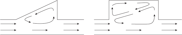
Also, of course, the volume of melt that they can
retain is very limited.
A useful design of dross trap appears to be a
volume at the end of the runner that is provided
with a narrow entrance (the extension shown in
broken outline in Figure 2.37b) to suppress any
outflow. It is a kind of wedge trap fitted with a
more capacious end. In the case of persistent
dross and slag problems, the trap can be exten-
ded, running around corners and into spare
nooks and crannies of the mould. If the entrance
section is less than the height of a sessile drop, it
will be filled by the entering liquid, thus being too
narrow to allow a reflected wave to exit. It should
therefore retain whatever material enters. In
addition, depending on the narrowness of the
tapered wedge entrance, to some extent the
device should be capable of filling and pressur-
izing the runner in a progressive manner akin to
the action of a gate. This is a useful technique to
reduce the initial transient momentum problems
that cause gates to fill too quickly during the first
few seconds. This potentially useful benefit has
yet to be researched more thoroughly so as to
provide useful guidelines for mould design.
The device can be envisaged to be useful in
combination with other forms of by-pass
designs such as those shown in 2.37d and e.
Slag pockets
For iron and steel castings the term `slag pocket'
is widely used for a raised portion of the runner
that is intended to collect slag. The large size of
slag particles and their large density difference
with the melt encourages such separation.
However, such techniques are not the panacea
that the casting engineer might wish for.
For instance the use of traps of wedge-shaped
design, Figure 2.51, is expected to be almost
completely ineffective because the circulation
pattern of flow would take out any material that
happened to enter. On the other hand, a rectan-
gular cavity has a secondary flow into which
buoyant material can transfer if it has sufficient
time, and so remain trapped in the upper
circulating eddy. This consideration again
emphasizes the need for relatively slow flow for its
effectiveness. Also, of course, none of these traps
can become effective until the runner and the trap
become filled with metal. Thus many filling
systems will have passed much if not all such
unwanted material before the separation mech-
anisms have a chance to come into operation. A
further consideration that causes the author to
hesitate to recommend such traps is that they
locally remove the constraint on the flow of the
metal, allowing surface turbulence. Thus the
traps might cause more problems than they solve.
Davis and Magny (1977) observed the filling
of iron and steel castings by video radiography.
They confirmed that most slag retention devices
either do not work at all, or work with only
partial effectiveness. These authors made cast-
ings with different amounts of slag, and tested
the ability of slag pockets sited above runners
to retain the slag. They found that rectangular
pockets were tolerably effective only if the
velocity of flow through the runner was below
0.4 m s
ÿ1
(interesting that this is precisely the
critical speed at which surface turbulence will
occur, and so cause surface phases to be tur-
bulently stirred back into the bulk liquid). For a
casting only 0.1 m high the metal is already
travelling four times too fast. For such reasons
the experience with slag pockets has been
somewhat mixed in practice.
In defence of the historical use of such traps it
must be borne in mind that they were tradi-
tionally used with pressurized filling systems,
heavily choked at the gate, so that the runner
was encouraged to fill as quickly as possible,
making the trap effective at an early stage of
filling. Also, if the choking action was suffi-
ciently severe the speed of flow in the runner
may be sufficiently slow to ensure slag entrap-
ment. However, this text does not recommend
pressurized filling systems mainly because of the
problems that follow from the necessarily high
ingate velocities.
Perhaps, therefore, the slag trap has come to
the end of its useful life.
Figure 2.51 Various designs of slag pockets: (a) relatively ineffective self-emptying wedge; (b) rectangular trap
stores buoyant phases in upper circulating flow.
Rule 2. Avoid turbulent entrainment 79
2.3.6.2 Swirl traps
The centripetal trap is an accurate name for this
device, but rather a mouthful. It is also known
as a whirl gate, or swirl gate, which is shorter,
but inaccurate since the device is not really a
gate at all. Choosing to combine the best of both
names, we can call it a swirl trap. This is con-
veniently short, and accurately indicates its
main purpose for trapping rubbish.
The idea behind the device is the use of the
difference in density between the melt and the
various unwanted materials which it may carry,
either floating on its surface or in suspension in
its interior. The spinning of the liquid creates a
centrifugal action, throwing the heavy melt
towards the outside where it escapes through the
exit, to continue its journey into the casting.
Conversely, the lighter materials are thrown
towards the centre, where they coagulate and
float. The centripetal acceleration a
c
is given by:
a
c
V
2
=r (2.9)
where V is the local velocity of the melt, and r is
the radius at that point. For a swirl trap of
50 mm radius and sprue heights of 0.1 m and
1 m, corresponding to velocities of 1.5 and
4.5 m s
ÿ1
respectively we find that accelerations
of 40 and 400 m s
ÿ2
respectively are experienced
by the melt. Given that the gravitational accel-
eration g is 9.81 m s
ÿ2
, which we shall approx-
imate to 10 m s
ÿ2
, these values illustrate that
the separating forces within a swirl trap can be
between 4 and 40 times that due to gravity. These
are, of course, the so-called `g' forces experienced
in centrifuges.
So much for the theory. What about the
reality?
Foundrymen have used swirl traps exten-
sively. This popularity is not easy to understand
because, unfortunately, it cannot be the result of
their effectiveness. In fact the traps have worked
so badly that Ruddle (1956) has recommended
not to use them on the grounds that their poor
performance does not justify the additional
complexity. One has to conclude that their
extraordinarily wide use is a reflection of the
fascination we all have with whirlpools, and an
unshakeable belief, despite all evidence to the
contrary, that the device should work.
Regrettably, the swirl trap is expected to be
completely useless for film-forming alloys where
inclusions in the form of films will be too slug-
gish to separate. Since some of the worst inclu-
sions are films, the swirl trap is usually worse
than useless, creating more films than it can
remove. Worse still, in the case of alloys of
aluminium and magnesium, their oxides are
denser than the metal, and so will be centrifuged
outwards, into the casting! Swirl traps are
therefore of no use at all for light alloys (how-
ever, notice that the vortex sprue base, although
not specifically designed to control inclusions,
might have some residual useful effect for light
alloys since the outlet is central). Finally, swirl
traps seem to be difficult to design to ensure
effective action. In the experience of the author,
most do much more harm than good.
The inevitable conclusion is that swirl traps
should be avoided.
The remainder of this section on swirl traps is
for those who refuse to give up, or refuse to
believe. It also serves as a mini-illustration of the
real complexity of apparently simple foundry
solutions. Such illustrations serve to keep us
humble.
It is worthwhile to examine why the tradi-
tional swirl trap performs so disappointingly.
On examination of the literature, the textbooks,
and designs in actual use in foundries, three
main faults stand out immediately:
1. The inlet and exit ducts from the swirl traps
are almost always opposed, as shown in
Figure 2.52a. The rotation of the metal as a
result of the tangential entry has, of course,
to be brought to a stop and reversed in
direction to make its exit from the trap. The
disorganized flow never develops its intended
rotation and cannot help to separate inclu-
sions with any effectiveness.
Where the inlet and exit ducts are arranged
inthecorrecttangentialsense,thenTrojanetal.
(1966) have found that efficiency is improved
in their model results using wood chips in
water. Even so, efficiencies in trapping the
chips varied between the wide limits of 50 and
100 per cent.
2. The inlet is nearly always arranged to be
higher than the exit. This elementary fault
gives two problems. First, any floating slag or
dross on the first metal to arrive is immedi-
ately carried out of the trap before the trap is
properly filled (Figure 2.52c). Second, as was
realized many years previously (Johnson and
Baker 1948), the premature escape of metal
hampers the setting up of a properly devel-
oped spinning action. Thus the trap is slow to
develop its effect, perhaps never achieving its
full speed in the short time available during
the pour. This unsatisfactory situation is also
seen in the work of Jirsa (1982), who describes
a swirl trap for steel casting made from
preformed refractory sections. In this design
the exit was again lower than the entrance,
and filling of the trap was encouraged merely
by making the exit smaller than the entrance.
80 Castings Practice: The 10 Rules of Castings
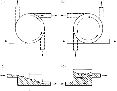
Much metal and slag almost certainly escaped
before the trap could be filled and become
fully operational. Since 90 per cent efficiency
was claimed for this design it seems probable
that all of the remaining 10 per cent which
evaded the trap did so before the trap was
filled (in other words, the trap was working
at zero efficiency during this early stage).
Jeancolas et al. (1971) report an 80 per cent
efficiency for their downhill swirl trap for
bronze and steel casting, but admit that the
trap does not work at all when only partly full.
3. In many designs of swirl trap there is
insufficient attention paid to providing ac-
commodation for the trapped material. For
instance, where the swirl trap has a closed top
the separated material will collect against the
centre of the ceiling of the trap. However,
work with transparent models illustrates
clearly how perturbations to the flow cause
the inclusions, especially if small, to ebb and
flow out of these areas back into the main
flow into the casting (Jeancolas et al. 1971;
Trojan et al. 1966). Also, of course, traps of
such limited volume are in danger of becom-
ing completely overwhelmed, becoming so
full of slag or dross that the flow into the
casting becomes necessarily contaminated.
Where the trap has an open top the parabolic
form of the liquid surface assists the con-
centration of the floating material in the central
`well' as shown in Figure 2.52d. The extra height
for the separated materials to rise into is useful
to keep the unwanted material well away from
the exit, despite variations from time to time in
flow rate. Some workers have opened out the
top of the trap, extending it to the top of the
cope, level with the pouring bush. This certainly
provides ample opportunity for slag to float well
clear, with no danger of the trap becoming
overloaded with slag. However, the author does
not recommend an open system of this kind,
because of the instability which open-channel
systems sometimes exhibit, causing surging and
slopping between the various components
comprising the `U'-tube effect between the
sprue, swirl trap and mould cavity.
It is clear that the optimum design for the
swirl trap must include the features:
(i) the entrance at the base of the trap;
(ii) the exit to be sited at a substantially higher
level;
(iii) both entrance and exit to have similar
tangential direction, and
(iv) an adequate height above the central axis to
provide for the accumulation of separated
debris.
In most situations the inlet will be moulded in
the drag, and the exit in the cope, which is the
most marginal difference in level between the
two. At the high speeds at which the metal can
be expected to enter the trap the metal will
surge over this small ledge with ease, taking
inclusions directly into the casting, particularly
if the inlet and outlet are in line as shown in
Figure 2.52b. This simplest form of cope/drag
parting line swirl trap cannot be expected to
work.
The trap may be expected to work somewhat
more effectively as the angle of the outlet pro-
gresses from 90±180 degrees. (The 270 degree
option would be more effective still, except that
some reflection will show it to be unmouldable
Figure 2.52 Swirl traps showing (a) incorrect
opposed inlet and exit ducts; (b) correct
tangential arrangements; (c) incorrect low exit;
(d) correct high exit.
Rule 2. Avoid turbulent entrainment 81
on this single joint line; the exit will overlay the
entrance ports! Clearly, for the 270 degree
option to be possible, the entrance and exits
have to be moulded at different levels, necessi-
tating a second joint line provided by a core or
additional mould part.)
When using preformed refractory sections, or
pre-formed baked sand cores, as is common for
larger steel castings, the exit can with advantage
be placed considerably higher than the entrance
(Figure 2.52d).
These simple rules are designed to assist the
trap to spin the metal up to full speed before the
exit is reached, and before any floating or
emulsified less-dense material has had a chance
to escape.
For the separation of particulate slag inclu-
sions from some irons and steels, Castings 1991
showed that a trap 100 mm diameter in the
running system of moulds 0.1 to 1 m high would
be expected to eliminate inclusions of 0.2 to
0.1 mm respectively. The conclusion was that,
when correctly designed, the swirl trap could be
a useful device to divert unwanted buoyant
particles away from ferrous castings.
We have to remember, however, that it is not
expected to work for film type inclusions.
Compared to particles, films would be expected
to take between 10 and 100 times longer to
separate under an equivalent field force. Thus
most of the important inclusions in a large
number of casting alloys will not be effectively
trapped. Thus the alloys that need the technique
most are least helped.
This damning conclusion applies to other
field forces such as electromagnetic techniques
that have recently been claimed to remove
inclusions from melts. It is true that forces can
be applied to non-conducting particles sus-
pended in the liquid. However, whereas com-
pact particles move relatively quickly, and can
be separated in the short time available while the
melt travels through the field. Films experience
the same force, but move too slowly because of
their high drag, and so are not removed.
In summary, we can conclude that apart
from certain designs of by-pass trap, other
varieties of traps are not recommended. In
general they almost certainly create more
inclusions than they remove.
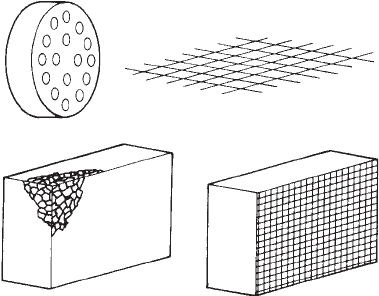
2.3.6.3 Filters
Filters take many forms: as simple strainers,
woven ceramic cloths, and ceramic blocks of
various types. Naturally, their effectiveness
varies from application to application, as is
discussed here.
Strainers
A sand or ceramic core may be moulded to
provide a coarse array of holes, of a size and
distribution resembling a domestic colander.
A typical strainer core might be a cylinder 30 to
50 mm diameter, 10 to 20 mm long, containing
10 or more holes, of diameter approximately
3±5 mm (Figure 2.53a). These devices are mainly
used to prevent slag entering iron castings. The
domestic colander is usually used to strain
aggregates such as peas. These represent solid
spherical particles of the order of 5 mm dia-
meter. Thus, when applied to most metal cast-
ings, the rather open design of strainers means
that they can hardly be expected to perform any
significant role as filters.
In fact, Webster (1967) has concluded that
the strainer works by reducing the rate of flow
of metal, assisting the upstream parts of the
filling system to prime, and thereby allowing the
slag to float. It can be held against the top
surface of the runner, or in special reservoirs
placed above the strainers to collect the retained
slag. Webster goes on to conclude that if the
strainer only acts to reduce the rate of flow, then
this can be carried out more simply and cheaply
by the proper design of the running system.
This may not be the whole story. The
strainer may be additionally useful to laminize
the flow (i.e. cause the flow to become more
streamlined).
However, whatever benefits the strainer may
have, its action to create jets downstream of the
strainer is definitely not helpful. The placing of a
strainer in a geometry that will quickly fill the
region at the back of the strainer would be a
Figure 2.53 Various filters showing (a) a strainer core
(hardly a filter at all); (b) woven cloth or mesh, forming a
two-dimensional filter; (c) ceramic foam and extruded
blocks, constituting three-dimensional filters.
82 Castings Practice: The 10 Rules of Castings
(c)
(a) (b)
great advantage. A geometry to suppress jetting
is provided by the tangential filter print to be
discussed later (Figure 2.56). The extruded or
pressed ceramic filters with their arrays of par-
allel pores are, of course, equivalent to strainers
with a finer pore size. They also benefit from the
tangential placement to the oncoming flow as
will be described.
Over the years there has been much work
carried out to quantify the benefits of the use
of filters. Nearly all of these have shown
measurable, and sometimes important, gains in
freedom from defects and improvements in
mechanical properties. These studies are too
numerous to list here, but include metals of all
types, including Al alloys, irons and steels. The
relatively few negative results can be traced to
the use of unfavourable siting or geometry of
the filter print. For positive and reliable results,
these aspects of the use of filters cannot be
overlooked. Special attention is devoted to them
in what follows.
Woven cloth or mesh
For light alloys, steel wire mesh or glass cloth
(Figure 2.53b) is used to prevent the oxides from
entering the casting. Cloth filter material has the
great advantage of low cost.
The surprising effectiveness of these rather
open meshes is the result of the most important
inclusions being in the form of films, which
appear to be intercepted by and wrap around
the strands of the mesh. Openings in the mesh or
weave are typically 1±2 mm; this gives good
results, being highly effective in retaining films
down to this size range. Significantly, it is also a
confirmation of the large size of the majority of
films that cause problems in castings, particu-
larly in light alloys.
The use of steel wire mesh is also useful to
retain films. The steel does not have time to go
into solution during the filling of aluminium
alloy castings, so that the material of the casting
is in no danger of contamination. However, of
course, the steel presents a problem of iron
contamination during the recycling of the run-
ning system. Even the glass cloth can sometimes
cause problems during the break-up of the
mould, when fragments of glass fibre can be
freed to find their way into the atmosphere of
the foundry, and cause breathing problems for
operators. Both materials therefore need care
in use.
Some glass cloth filters are partially rigidized
with a ceramic binder, and some by impregna-
tion with phenolic resin. (The outgassing of the
resin can cause the evolution of large bubbles
when contacted by the liquid metal. Provided
the bubbles do not find their way into the
casting the overall effect of the filters is defi-
nitely beneficial in aluminum alloys.) Both types
soften at high temperature, permitting the cloth
to stretch and deform.
A woven cloth based on a high silica fibre has
been developed to avoid softening at these
temperatures, and might therefore be very suit-
able for use with light alloys. In fact at the
present time its high-temperature performance
usually confines its use to copper-based alloys
and cast irons. There are few data to report on
the use of this material. However, it is expected
that its use will be similar to that of the other
meshes, so that the principles discussed here
should still apply.
Despite the attraction of low cost, it has to be
admitted that, in general, the glass cloth filters
are not easy to use successfully.
For instance, as the cloth softens and stret-
ches there is a strong possibility that the cloth
will allow the metal to by-pass the filter. It is
essential to take this problem into account when
deciding on the printing of the filter. Clearly, it
is best if it can be firmly trapped on all of its
edges. If it can be held on only three of its four
edges the vulnerability of the unsupported edge
needs careful consideration. For instance, even
though a cross-joint filter may be properly held
on the edges that are available, the filter is
sometimes defeated by the leading edge of the
cloth bending out of straight, bowing like a sail,
and thus allowing the liquid to jet past. All the
filters shown in Figure 2.54 show this problem.
It may be better to abandon cloth filtration if
there is any danger of the melt jetting around a
collapsing filter.
When sited at the point where the flow
crosses a joint as in Figure 2.54 a greensand
mould will probably hold the cloth successfully,
the sand impressing itself into the weave, pro-
vided sufficient area of the cloth is trapped in
the mould joint. In the case of a hard sand
mould or metal die, the cloth requires a shallow
print which must be deep enough to allow it
room if the joint is not to be held apart. Also, of
course, the print must not be too deep, other-
wise the cloth will not be held tight, and may be
pulled out of position by the force of the liquid
metal. Some slight crushing of a hard sand
mould is desirable to hold the cloth as firmly as
possible.
A rigidized cloth filter can be inserted across
the flow by simply fitting it into the pattern in a
pre-moulded slot across the runner and so
moulding it integral with the mould (Figure 2.54c).
However, this is only successful for relatively
small castings. Where the runner area becomes
large and the time and temperature become too
Rule 2. Avoid turbulent entrainment 83
high, the filter softens and bows in the force of
the flow. Even if it is not entirely pulled out of
position it may be deformed to sag like a fence
in a gale, so that metal is able to flow over the
top. This is the reason for the design shown in
Figure 2.54e. The edge of the filter crosses the
joint line, either to sit in a recess accurately
provided on the other half of the mould, or if the
upstand is limited to a millimetre or so, to be
simply crushed against the other mould half.
(The creation of some loose grains of sand is of
little consequence in the running system, as has
been shown by Davis and Magny (1977); loose
material in the runner is never picked up by the
metal and carried into the mould. The author
can confirm this observation as particularly true
for systems that are not too turbulent. The
laminizing action of the filter itself is probably
additionally helpful.)
If the filter is introduced at an earlier stage of
manufacture during the production of a sand
mould, it can be placed in position in a slot cut
in the runner pattern. When the sand is intro-
duced the filter is automatically bonded into
the mould (Figure 2.54d). Again, an upstand
above the level of the joint may be useful
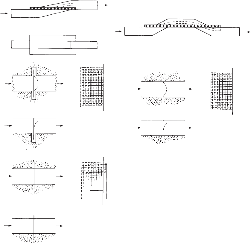
Figure 2.54 Siting of cloth filters (a) in the mould joint; (b) in a double crossing of the joint; (c) in a slot moulded across
the runner; (d) in a slot cut in the runner pattern; (e) with an additional upstand across the joint plane to assist sealing.
84 Castings Practice: The 10 Rules of Castings
(a) (b)
(c) (d)
(e)
(Figure 2.54e). In any case, when using filters
across runners, it also helps to arrange for the
selvage (the reinforced edge of the material) of
the cloth to be uppermost to give the unsup-
ported edge most strength; the ragged cut edge
has little strength, letting the cloth bend easily,
and allowing some, or perhaps all, of the flow to
avoid the filter. All the cloth filters used as
shown in Figure 2.54 are defeatable, since they
are held only on three sides. The fourth side is
the point of weakness. Failure of the filter by the
liquid overshooting this unsupported edge can
result in the creation of more oxide dross than
the filter was intended to prevent! Increasing the
trapped area of filter in the mould joint can
significantly reduce the problem.
Geometries that combine bubble traps (or
slag or any other low density phase) are shown
in Figure 2.55 for in-line arrangements, and for
those common occasions when the runner is
required to be divided to go in opposite direc-
tions. With shallow runners of depth of a few
millimetres there is little practical difference in
whether the metal goes up or down through the
filter. Thus several permutations of these geo-
metries can be envisaged. Much depends on the
links to the gates, and how the gates are to be
placed on the casting. In general, however,
I usually aim to have the runner exit from the
filter below the joint.
Cloth filters are entirely satisfactory where
they can be held around all four sides. This is the
case at the point where gates are taken vertically
upwards from the top of the runner. This is
a relatively unusual situation, where, instead of
a two-parted mould, a third mould part forms a
base to the mould and allows the runner system
to be located under the casting. Alternatively, a
special core can be used to create an extra joint
beneath the general level of the casting.
Another technique for holding the filter on
all sides is the use of a `window frame' of strong
paper or cardboard that is bonded or stapled to
the cloth. The frame is quickly dropped into its
slot print in the mould, and gives a low cost rigid
surround that survives sufficiently long to be
effective.
Ceramic block filters
Ceramic block filters of various types intro-
duced in about 1980 have become popular, and
have demonstrated impressive effectiveness in
many applications in running systems.
Unfortunately, much that has been written
about the mechanisms by which they clean up
the cast material appears to be irrelevant. This is
because most speculation about the filtration
mechanisms has considered only particulate
inclusions. As has become quite clear over recent
years, the most important and widespread
inclusions are actually films. Thus the filtration
mechanism at work is clearly quite different,
and, in fact, easily understood.
In aluminium alloys the action of a ceramic
foam filter to stop films has, in general, not been
recognized. This is probably because the films
are so thin (a new film may be only 20 nm thick,
making the doubled-over entrained bifilm still
only about 40 nm) that they cannot be detected
when wrapped around sections of the ceramic
filter. This explains part of the curious experi-
ence of finding that a filter has cleaned up a
casting, but on sectioning the filter to examine it
Figure 2.55 Uses of glass cloth filtration (a) for an in line
runner; (b) for transverse runners.
Rule 2. Avoid turbulent entrainment 85
(a)
Glass cloth
(b)
under the microscope, not a single inclusion can
be found.
The contributing effect, of course, is that the
filter acts to improve the filling behaviour of
the casting, so reducing the number of inclu-
sions that are created in the mould during the
filling process. This behaviour was confirmed
by Din et al. (2003) who found only about
10 per cent of the action of the filter was the
result of filtration, but 90 per cent was the
result of improved flow.
A further widespread foundry experience is
worth a comment. On occasions the quantity of
inclusions has been so great that the filter has
become blocked and the mould has not filled
completely. Such experiences have caused some
users to avoid the use of filters. However, in the
experience of the author, such unfortunate
events have resulted from the use of poor front
ends of filling systems (poor basin and sprue
designs) that create huge quantities of oxide
films in the pouring process. The filter has
therefore been overloaded, leading either to its
apparently impressive performance, or its fail-
ure by blockage. The general advice given to
users by filter manufacturers that filters will
only pass limited quantities of metal is seen to be
influenced by similar experience. The author has
not found any limit to the volume of metal that
can be put through a filter without danger of
blockage, provided the metal is sufficiently clean
and the front end of the filling system is
designed to perform well.
Thus the secret of producing good castings
using a filter is to team a good front end of the
filling system together with the filter. (If the
remainder of the filling system design is good, this
will, of course, help additionally.) Little oxide is
then entrained, so that the filter appears to do
little filtration. However,it is then fully enabled to
serve a valuable role as a flow rate control device.
The beneficial action of the filter in this case is
probably the result of several factors:
(i) The reduction in velocity of the flow
(provided an appropriately sized cross-
section area channel is provided down-
stream of course). This is probably the
single most important action of the filter.
However, there are other important actions
listed below.
(ii) Reduces the time for the back-filling of the
sprue, thereby reducing entrainment defects
from this source.
(iii) Smooths fluctuations in flow.
(iv) Laminizes flow, and thus aids fluidity a
little.
(v) The freezing of part of the melt inside the
filter by the chilling action of the filter (as
predicted for Al alloys in ceramic foam
filters by computer simulation and found
by experiment by Gebelin and Jolly 2003)
may be an advantage, because this may act
to restrict flow, and so to reduce delivery
from the filter in its early moments. The
subsequent re-melting of the metal as more
hot metal continues to pass through the
filter will allow the flow to speed up to its
full rate later during filling. (Interestingly,
this advantage did not apply to preheated
ceramic moulds where the preheat was
sufficient to prevent any freezing in the
filter).
There are different types of ceramic block filter.
(i) Foam filters made by impregnation of
open-cell plastic foams with a ceramic
slurry, squeezing out the excess slurry, and
firing to burn out the plastic and develop
strength in the ceramic. The foam structure
consists of a skeleton of ceramic filaments
and struts defining a network of intercon-
necting passageways.
(ii) Extruded forms that have long, straight,
parallel holes. They are sometimes referred
to as cellular filters.
(iii) Pressed forms, again with long, straight but
slightly tapered holes. The filters are made
individually from a blank of mouldable clay
by a simple pressing operation in a two-part
steel die.
(iv) Sintered forms, in which crushed and
graded ceramic particles are mixed with a
ceramic binder and fired.
In all types the average pore size can be con-
trolled in the range 2±0.5 mm approximately,
although the sintered variety can achieve at least
2±0.05 mm. Insufficient research (other than
that funded by the filter manufacturers!) has
been carried out so far to be sure whether there
are any significant differences in the perfor-
mance between them. An early result of Khan
et al. (1987) found that the fatigue strength of
ductile iron was improved by extruded cellular
filters, but that the foam filters were unpredict-
able, with results varying from the best to the
worst. Their mode of use of the filters was less
than optimum, being blasted by metal in the
entrance to the runner, and with no back pro-
tection for the melt. (We shall deal with these
aspects below.) The result underlines the prob-
able unrealized potential of both types, and
reminds us that both would almost certainly
benefit from the use of recent developments. In
general, we have to conclude that the published
comparisons made so far are, unfortunately,
often not reliable.
86 Castings Practice: The 10 Rules of Castings
For aluminium alloys the results are less
controversial, because the filters are highly
effective in removing films which have, of
course, a powerful effect on mechanical prop-
erties. Mollard and Davidson (1978) are typical
in their findings that the strength of Al±7Si±Mg
alloy is improved by 50 per cent, and elongation
to failure is doubled. This kind of result is now
common experience in the industry.
For some irons and steels, where a high
proportion of the inclusions will be liquid, most
filter materials are expected to be wetted by the
inclusion so that collection efficiency will be
high for those inclusions. Ali et al. (1985) found
that for alumina inclusions in steel traversing an
alumina filter, once an inclusion made contact
with the filter it became an integral part of the
filter. It effectively sintered into place; despite
the fact that both inclusion and filter are solid at
the temperature of operation, they behave as
though they are `sticky'. This behaviour is likely
to characterize many types of inclusion at the
temperature of liquid steel.
In contrast with this, Wieser and Dutta
(1986) find that whereas alumina inclusions in
steel are retained by an alumina filter, even up to
the point at which it will clog, deoxidation of
steel with Mn and Si produces silica-containing
products that are not retained by an extruded
zirconia spinel filter. These authors also tested
various locations of the filter, discovering that
placing it in the pouring basin was of no
use, because it was attacked by the slag and
dissolved!
Although these results might have been
influenced by the rapid flow rates that appear to
have been used in this work, it is a warning that
filtration efficiency is likely to be strongly
dependent on inclusion and filter types. Ali et al.
(1985) confirms this strong effect of velocity,
finding only at very low velocities measured in
mm s
ÿ1
was a high level (96 per cent) of filtra-
tion achieved in steel melts.
Block filters are more expensive than cloth
filters. However, they are easier to use and more
reliable. They retain sufficient rigidity to mini-
mize any danger of distortion that might result
in the by-passing of the filter. It is, however,
important to secure a supply of filters that are
manufactured within a close size tolerance, so
that they will fit immediately into a print in the
sand mould or into a location in a die, with
minimal danger of leakage around the sides of
the filter. Although all filter types have
improved in this respect over recent years, the
foam filter seems most difficult to control, the
extruded is intermediate, whereas the pressed
filter exhibits good accuracy and reproducibility
as a result of it being made in a steel die; residual
variation seems to be result of poor control of
shrinkage on firing.
Leakage control
It is essential to control the leakage past the
filter. There are various techniques.
(i) A seating of a compressible gasket of
ceramic paper. This approach is useful when
introducing filters into metal dies, where the
filter is held by the closing of the two halves
of the die. The variations in size of the filters,
and the variability of the size and fit of the
die parts with time and temperature, which
would otherwise cause occasional cracking
or crushing of the rather brittle filter, are
accommodated safely by the gasket.
(ii) Moulding the filter directly into an aggre-
gate (sand) mould. This is achieved simply
by placing the filter on the pattern, and
filling the mould box or core box with
aggregate in the normal way. The filter is
then perfectly held. In greensand systems or
chemically bonded sands the mould materi-
al seems not to penetrate a ceramic foam
filter more than the first pore depth. This is
a smaller loss than would be suffered when
using a normal geometrical print. However,
the technique often requires other measures
such as the moulding of the filter into a
separate core, or the provision of a loose
piece in the pattern to form the channel on
the underside of the filter.
There are other aspects of the siting of filters in
running systems that are worth underlining.
(i) Siting a filter so that some metal can flow by
(into a slag trap for instance) prior to
priming the filter is suggested to have the
additional benefit that the preheat of the
filter and the metal reduces the priming
problem associated with the chilling of the
metal by the filter (Wieser and Dutta 1986).
An example is seen in Figure 2.56d.
(ii) The area of the filter needs to be adequate.
There is much evidence to support the fact
that the larger the area (thereby giving a
lower velocity of flow through the filter) the
better the effectiveness of the filter. For
instance, if the filter area is too small in
relation to the velocity of flow then the filter
will be unable to retain foreign matter: the
force of the flow will strip away retained
films like sheets from the washing line in a
hurricane; particles and droplets will follow
a similar fate.
Rule 2. Avoid turbulent entrainment 87