Jenkins N., Strbac G., Ekanayake J. Distributed Generation
Подождите немного. Документ загружается.

A resistor in one side (primary or secondary) of the transformer circuit can be
referred to the other side by equating the energy dissipated in them as heat. For
example, the heat loss associated with R
1
(on the primary side) is I
2
1
R
1
. If that
resistor is transferred to the secondary side an equivalent resistance is R
0
1
, then:
I
2
2
R
0
1
¼ I
2
1
R
1
R
0
1
¼
I
1
I
2
2
R
1
ðIV:5Þ
Substituting for the current ratio from (IV.4) into (IV.5):
R
0
1
¼
N
2
N
1
2
R
1
ðIV:6Þ
The primary leakage reactance may also be referred to the secondary side in a
similar manner:
X
0
1
¼
N
2
N
1
2
X
1
ðIV:7Þ
Typically, the current through the magnetising branch of a transformer (X
m
and R
c
) is only about 3–5% of the full-load current. Therefore when considering a
loaded transformer, the magnetising branch is usually omitted. The equivalent
circuit of a loaded transformer where all the quantities are referred to the secondary
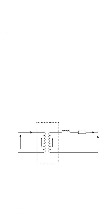
is shown in Figure IV.4.
E
2
N
1
:N
2
X
L
R
L
E
1
V
1
V
2
I
2
I
1
Ideal
transformer
Figure IV.4 Simplified circuit of a transformer
In Figure IV.4:
R
L
¼R
2
þ
N
2
N
1
2
R
1
X
L
¼X
2
þ
N
2
N
1
2
X
1
ðIV:8Þ
The windings of practical power transformers are usually tapped to allow
alteration of the number of turns in use and hence the turns ratio of the transformer.
Power systems 247
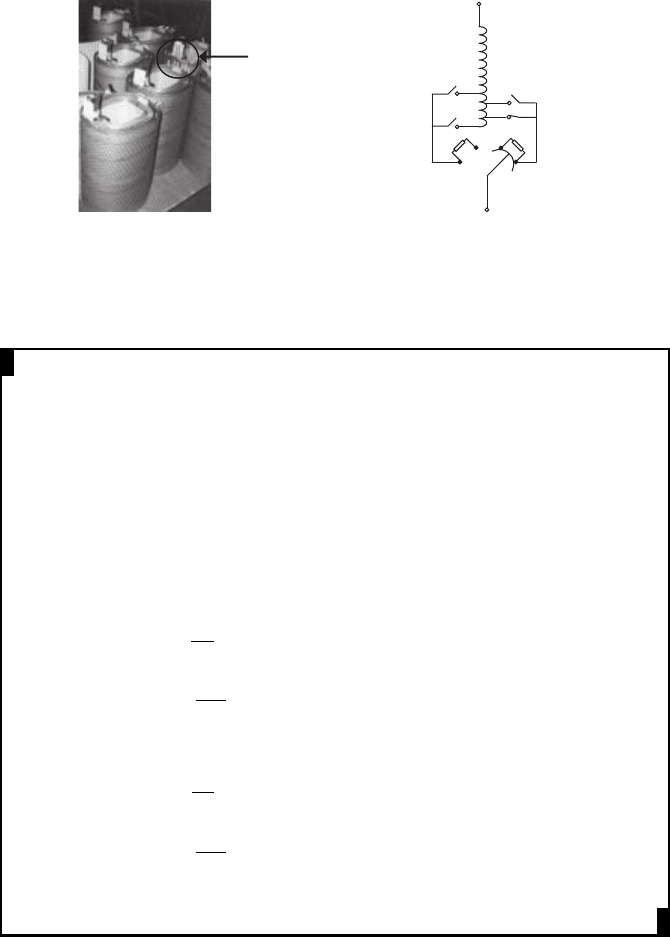
In this way the secondary voltage may be altered (with a constant primary voltage).
On load tap changers use a combination of diverter and selector switches to change
the transformer ratio while it passes current and is on load (Figure IV.5). Off load tap
changers can be operated with voltage on the transformer (but no current flowing),
while off circuit tap changers can only be operated when the transformer is isolated.
Transformer windings Arrangement typically used fo
r
chan
g
in
g
transformer taps
Taps taken out
for the tap
changer
connection
Figure IV.5 Transformer winding and tap changing arrangement
EXAMPLE IV.1
A 50 kVA transformer has 400 turns on the primary and 40 turns on the
secondary. The primary and secondary resistances are 0.3 W and 0.01 W
respectively, and the corresponding leakage reactances are j1.1 W and j0.035
W respectively. Calculate the equivalent impedance referred to the primary.
Answer:
Since the resistance and reactance are transformed from the secondary to the
primary, the transformation is based on the square of the primary to sec-
ondary turns ratio, thus if the equivalent impedance referred to the primary is
R
Lp
þ jX
Lp
:
R
Lp
¼ R
1
þ
N
1
N
2
2
R
2
¼ 0:3 þ
400
40
2
0:01
¼ 1:3 W
X
Lp
¼ X
1
þ
N
1
N
2
2
X
2
¼ 1:1 þ
400
40
2
0:035
¼ 4:6 W
248 Distributed generation

IV.3 Per-unit system
The power system has multiple voltage levels from 765 kV, down to 400 V or even
120 V and this makes circuit analysis rather confusing. By converting all the
quantities into dimensionless quantities, known as per-unit (pu) quantities, it is much
easier to analyse the power system. The pu quantity of any value is defined as the
ratio between the actual value of the quantity and the base or reference value in
the same unit. The per-unit system avoids confusion with transformers, where the
impedance of transformers depends on the side from which it is viewed, and elim-
inates the factor of
ffiffiffi
3
p
involved in line and phase voltage and current quantities. The
per-unit normalisation applies only to magnitudes and angles are not normalised.
The per-unit calculation starts with defining base values for power system
quantities. First, choose one base power (VA) for the entire power system being
studied. This value is arbitrarily chosen, normally appropriate for the size of the
system (a common choice for a large power system is 100 MVA). Second, one base
voltage is chosen for each voltage level. Usually this is the nominal voltage on each
side of the transformers; defined by the nominal turns ratio of the transformer.
Finally, other base values are calculated to get the same relationship between per-
unit quantities as between actual quantities.
For a distributed generator calculation, a suitable MVA base, S
b
, is first cho-
sen. The line-to-line voltages, V
L
, of the various voltage levels are selected as the
voltage bases (V
b
). The current and impedance base are then obtained as:
I
b
¼
S
b
ffiffiffi
3
p
V
b
ðIV:9Þ
Z
b
¼
V
b
=
ffiffiffi
3
p
I
b
¼
V
b
=
ffiffiffi
3
p
S
b
=
ffiffiffi
3
p
V
b
¼
½V
b
2
S
b
ðIV:10Þ
For example, if V
L
= 33 kV and S
b
= 100 MVA, Z
b
is given by:
Z
b
¼
ð33 10
3
Þ
2
100 10
6
¼ 10 :86 W
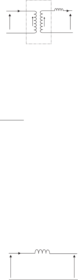
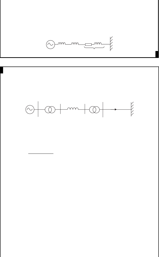
IV.3.1 Power transformers in per unit
For three-phase transformers in a power system, the resistances are much smaller
than reactances. Therefore, the per-phase transformer equivalent circuit shown in
Figure IV.4 is simplified by neglecting the resistance (Figure IV.6).
For a transformer two base voltages are defined: primary voltage, V
L1
, and the
secondary voltage, V
L2
.
From Figure IV.6:
E
1
¼ V
1
ðIV:11Þ
E
2
¼ V
2
þ jI
2
X
L
ðIV:12Þ
Power systems 249
By dividing (IV.11) by V
L1
=
ffiffiffi
3
p
(as the equation is a per-phase equation):
E
1;pu
¼ V
1;pu
¼ 1pu ðIV:13Þ
Similarly by dividing (IV.12) by V
L2
=
ffiffiffi
3
p
:
E
2;pu
¼ V
2;pu
þ
jI
2
X
L
ðV
L2
=
ffiffiffi
3
p
Þ
¼ 1pu ðIV:14Þ
From (IV.9) and (IV.10):
I
b
Z
b
¼ V
L2
=
ffiffiffi
3
p
ðIV:15Þ
Therefore, (IV.14) was rewritten as:
E
2;pu
¼ V
2;pu
þ jI
2;pu
X
L;pu
¼ 1pu ðIV:16Þ
From (IV.13) and (IV.16):
V
1;pu
¼ V
2;pu
þ jI
2;pu
X
L;pu
ðIV:17Þ
Therefore, the transformer is represen ted by the equivalent circuit shown in
Figure IV.7 in per unit.
X
L
, pu
V
1, pu
V
2, pu
I
1, pu
Figure IV.7 Transformer equivalent circuit in pu
The equivale nt leakage reactance of the transformer, X
L
, is normally defined
as a percentage on its own name-plate rating. For example a transformer impedance
of 6% on a 1 MVA transformer is simply: X
L
= 0.06 pu, S
b
= 1 MVA.
E
2
N
1
:N
2
X
L
E
1
V
1
V
2
I
1
I
2
Ideal
transforme
r
Figure IV.6 A simplified circuit of a power transformer
250 Distributed generation
IV.3.2 Generators
As discussed in Tutorial II, a generator also has an internal impedance where the
resistive component is very small compared to the inductive component. The
internal impedance of the generat or is generally represented by a percentage, which
is the internal reactance in pu on the machine base multiplied by 100.
IV.3.3 System studies
To study a system using the pu system, all quantities are expressed in a consistent
manner, that is on the same base power for the whole syst em being studied and the
same base voltage for all the components at a voltage level. In many case s, the
impedances of the transformers and generators are given on their own name-plate VA
bases. It is then necessary to convert these impedances into the common system base.
Assume that a pu impedance, Z
1
, is given on a power base of S
b1
. If the ohmic
value of the impedance is Z. Then from (IV.10):
Z
1
¼
Z
Z
b1
¼ Z
S
b1
V
2
L
ðIV:18Þ
The impedance Z can be translated to a per unit impedance, Z
2
, on a power
base of S
b2
as:
Z
2
¼
Z
Z
b2
¼ Z
S
b2
V
2
L
ðIV:19Þ
From (IV.18) and (IV.19):
Z
2
¼ Z
1
S
b2
S
b1
ðIV:20Þ
EXAMPLE IV.2
Using a 10 MVA base, change all the parameters in the following circuit into
per unit and draw the simplified equivalent circuit.
12.5:33 kV
15 MVA
15%
Distribution line
impedance = 10 + j 50 Ω
12.5 kV
10 MVA
35%
Answer:
Assume voltage bases of: 12.5 kV for the primary side of the transformer and
33 kV for the secondary side of the transformer.
On 10 MVA base, the generator reactance is 35% = j 0.35 pu.
The transformer impedance is equal to j 0.15 pu on a 15 MVA base.
From (IV.20), on a 10 MVA base it is equal to j 0.15 10/15 = j 0.1 pu.
Power systems 251
On 33 kV, 10 MVA, the base impedance is given by: Z
b
= (33 10
3
)
2
/
10 10
6
= 108.6 W
The per unit impedance of the distribution line is (10 þ j50)/108.6 =
0.092 þ j0.46 pu.
Then system in pu is drawn as:
0.092 +
j
0.46 1 pu
j 0.1
i 0.35
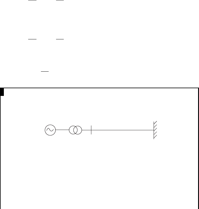
EXAMPLE IV.3
A schematic diagram of a radial network with a distributed generator is
shown here. Calculate the terminal voltage of the synchronous generator if
the voltage at busbar A at 30 kV. Use a 100 MVA base.
11:132 kV
50 MVA
X = 10%
132:33 kV
50 MVA
X = 12%
j 50 Ω
25 MW
0.8 pf lagging
V
s
Busbar A
Answer:
On V
b
= 132 kV and S
b
= 100 MVA, Z
b
is given by:
Z
b
¼
ð132 10
3
Þ
2
100 10
6
¼ 174: 24 W
The 11:132 kV transformer impedance on 100 MVA base = j0.1 (100/
50) = j0.2 pu.
The 132:33 kV transformer impedance on 100 MVA base = j0.12
(100/50) = j0.24 pu.
The line impedance (j 50 W) on 132 kV, 100 MVA base = j50/174.24 =
j0.287 pu.
Since cos f = 0.8, f = 36.87
Therefore, reactive power absorbed by the main system = (25/cos f)
sin f = (25/0.8) 0.6. = 18.75 MVAr
Load power in pu = (P þjQ)/S
b
= (25 þ j18.75)/100 = 0.25 þ j0.1875 pu.
As the voltage at busbar A is 30 kV, on a 33 kV base it is 30/33 pu =
0.909 pu. Defining this voltage as the reference voltage:
V
L
I
L
¼ 0:25 þ j0:1875
0:909 I
L
¼ 0:25 þ j0:1875
I
L
¼ 0:275 j0:206
252 Distributed generation
1
See Figure I.13 in Tutorial I.
Now for the radial distribution system, the following equation was written
in pu:
V
S
¼ V
L
þI
L
jð0:2 þ 0:24 þ 0:287Þ
¼ 0:909 þð0:275 j0:206Þj0:727
¼ 0:909 þ 0:15 þ j0:2
¼ 1:059 þ j0:2
¼ 1:08ff10:7
pu
On the 11 kV base, the generator terminal voltage = 1.08 11 = 11.88 kV.
IV.4 Symmetrical components
A three-phase system operating under balanced, symmetrical conditions was dis-
cussed in Tutorial I. However, unsymmetrical conditions often occur in the power
system due to unbalanced loading and asymmetrical faults (line–ground, line–line,
etc.). In order to analyse the power system under unsymmetrical conditions, the
system of symmetrical components is used. The basis is that any set of unbalanced
three-phase voltages or currents can be represented by three balanced sets of pha-
sors – positive, negative and zero – as shown in Figure IV.8.
The positive sequence phasor voltages have the same phase sequence
1
(ABC)
as the three-phase electrical power system. If the phase sequence of three voltages
is ACB, then these voltage components are called the negative sequence compo-
nents. The components where three voltages are equal in magnitude and phase are
called zero sequence components.
The phasor representation of the zero sequence voltages (subscript 0 refers to
zero sequence):
V
A0
¼ V
B0
¼ V
C0
¼ V
0
ff0
¼ V
0
e
j0
ðIV:21Þ
(
a
)
Positive sequence
(
b
)
ne
g
ative sequence
(
c
)
Zero sequence
V
A1
V
B1
V
C1
120°
120°
ω
V
A2
V
C2
V
B2
120°
120°
ω
V
A0
V
B0
V
C0
ω
Figure IV.8 Phasor representation of a three-phase voltage system
Power systems 253
The phasor representation of the positive sequence voltages (subscript 1 refers
to positive sequence):
V
A1
¼ V
1
ff0
¼ V
1
e
j0
V
B1
¼ V
1
ff120
¼ V
1
e
j2p=3
¼ V
1
e
j4p=3
V
C1
¼ V
1
ff240
¼ V
1
e
j4p=3
¼ V
1
e
j2p=3
ðIV:22Þ
Let l = e
j2p/3
, then:
V
B1
¼ V
A1
l
2
V
C1
¼ V
A1
l
ðIV:23Þ
The phasor representation of the negative sequence voltages (subscript 2 refers
to the negative sequence):
V
A2
¼ V
2
ff0
¼ V
2
e
j0
V
B2
¼ V
2
ff240
¼ V
2
e
j4p=3
¼ V
2
e
j2p=3
V
C2
¼ V
2
ff120
¼ V
2
e
j2p=3
¼ V
2
e
j4p=3
ðIV:24Þ
Then:
V
B2
¼ V
A2
l
V
C2
¼ V
A2
l
2
ðIV:25Þ
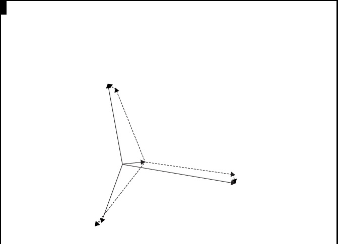
EXAMPLE IV.4
Using a phasor diagram show that the three unbalanced currents I
A
=
200 ff 10
, I
B
= 250 ff100
and I
C
= 150 ff200
can be represented by the
addition of positive, negative and zero sequence currents.
Answer:
I
A
I
B
I
A1
I
B1
I
C
I
C1
I
C2
I
B2
I
A2
I
A0
= I
B0
= I
C0
254 Distributed generation

As shown in the above diagram, the unbalanced currents can be repre-
sented by the addition of positive sequence currents (dashed lines) having a
magnitude of 196 A, where I
A1
leads I
A
by 22
, negative sequence currents
(dotted lines) having a magnitude of 19 A, where I
A2
leads I
A
by 57
, and
zero sequence currents (solid lines) having a magnitude of 54 A, where I
A0
lags I
A
by 85
.
As any unbalanced set of three-phase voltages or currents can be represented
by the addition of the zero, positive and negative sequence voltage or currents, for
voltages:
V
A
¼ðV
A0
þ V
A1
þ V
A2
Þ
V
B
¼ðV
B0
þ V
B1
þV
B2
Þ
V
C
¼ðV
C0
þ V
C1
þV
C2
Þ
ðIV:26Þ
Equation (IV.26) was rewritten by substituting from (IV.21), (IV.23) and
(IV.25):
V
A
¼ðV
A0
þ V
A1
þ V
A2
Þ
V
B
¼ðV
A0
þ l
2
V
A1
þ lV
A2
Þ
V
C
¼ðV
A0
þ lV
A1
þ l
2
V
A2
Þ
ðIV:27Þ
In matrix form:
V
A
V
B
V
C
2
4
3
5
¼
11 1
1 l
2
l
1 ll
2
2
4
3
5
V
A0
V
A1
V
A2
2
4
3
5
ðIV:28Þ
If V
A
, V
B
and V
C
are known then the three sequence component may be
found by:
V
A0
V
A1
V
A2
2
4
3
5
¼
11 1
1 l
2
l
1 ll
2
2
4
3
5
1
V
A
V
B
V
C
2
4
3
5
ðIV:29Þ
In order to find the inverse of
11 1
1 l
2
l
1 ll
2
2
4
3
5
;
11 1
1 l
2
l
1 ll
2
2
4
3
5
11 1
1 ll
2
1 l
2
l
2
4
3
5
Power systems 255
is considered:
11 1
1 l
2
l
1 ll
2
2
4
3
5
11 1
1 ll
2
1 l
2
l
2
4
3
5
¼
3 ð1 þl þl
2
Þð1 þl þl
2
Þ
ð1 þl þl
2
Þð1 þ2l
3
Þð1 þl
2
þl
4
Þ
ð1 þl þl
2
Þð1 þl
2
þl
4
Þð1 þ2l
3
Þ
2
4
3
5
ðIV:30Þ
Figure IV.9 shows how phasors are rotated with the l operator. From the figure it
may be seen that (1 þ l þ l
2
) = 0, (1 þ 2l
3
) = 3 and (1 þ l
2
þ l
4
)=0.
x
y
1
3
4
2
Figure IV.9 l operator
From (IV.30):
11 1
1 l
2
l
1 ll
2
2
4
3
5
11 1
1 ll
2
1 l
2
l
2
4
3
5
¼ 3
100
010
001
2
4
3
5
ðIV:31Þ
Therefore from matrix algebra:
2
11 1
1 l
2
l
1 ll
2
2
4
3
5
1
¼
1
3
11 1
1 ll
2
1 l
2
l
2
4
3
5
ðIV:32Þ
Thus from (IV.29):
V
A0
V
A1
V
A2
2
4
3
5
¼
1
3
11 1
1 ll
2
1 l
2
l
2
4
3
5
V
A
V
B
V
C
2
4
3
5
ðIV:33Þ
IV.5 Problems
1. A single-phase transformer has a primary/secondary turns ratio of 0.5. The
total resistance and reactance referred to the secondary side are 2.5 W and 10 W
2
[A] [B] = 3[I], [A] [B]/[A] = 3[I]/[A], [B] = 3[A]
1
, [A]
1
= 1/3[B]
256 Distributed generation