Jenkins N., Strbac G., Ekanayake J. Distributed Generation
Подождите немного. Документ загружается.

The relationship between the line and phase currents can be obtained by
assuming the three phase currents are balanced (i.e. the connected loads are equal).
From Figure I.15, the magnitude of the line current is equal to
ffiffiffi
3
p
times the mag-
nitude of the phase current.
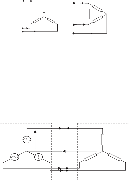
I.9 Connection of loads
Loads can also be connected in star or delta. If the loading on each phase is equal,
then that load is called a balanced three-phase load. Figure I.16(a) and (b) shows
balanced star-connected and delta-connected loads.
(
a
)
Star connection
(
b
)
Delta connection
I
A
I
B
I
C
Z∠
f
Z∠f
Z∠f
I
A
I
B
I
C
Z∠f
Z∠f
Z∠f
Figure I.16 Star and delta connection of loads
I.10 Three-phase four-wire system
A three-phase star-connected generation system is connected to a three-phase star-
connected load as shown in Figure I.17 to form a three-phase four-wire system.
Three-phase balanced star-
connected supply
I
A
I
B
I
C
I
N
V
AN
Z∠f
Z∠f
Z∠f
Three-phase balanced star-
connected load
Figure I.17 Configuration of the three-phase four-wire system
AC electrical systems 197
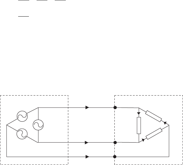
When the load is balanced, the current in the neutral wire is zero.
I
N
¼ I
A
þI
B
þI
C
¼
V
AN
Zfff
þ
V
BN
Zfff
þ
V
CN
Zfff
¼
V
m
Zfff
½sin wt þ sinðwt 2p=3Þþsinðwt 4p=3Þ ¼ 0
ðI:12Þ
However, when the loads are not balanced (i.e. the three loads are not equal),
then there will be a current flowing through the neutral wire.
I.11 Three-phase delta-connected three-wire system
Three-phase balanced
delta-connected load
I
A
I
B
I
C
I
1
I
2
I
3
Three-phase balanced
delta-connected source
Z∠f
Z∠f
Z∠f
Figure I.18 Three-phase delta-connected source and a load
A three-phase delta-connected generator is connected to a three-phase delta-con-
nected load as shown in Figure I.18 to form the three-phase, three-wire system. In
the figure I
A
, I
B
and I
C
are line currents, and I
1
, I
2
and I
3
are phase currents.
I
A
¼ I
1
I
3
; I
B
¼ I
2
I
1
and I
C
¼ I
3
I
2
ðI:13Þ
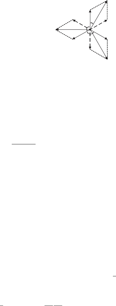
The corresponding phasor diagram of the system is shown in Figure I.19.
Defining the rms value of the magnitude of phase currents as I
p
and the rms value
of the magnitude of line currents as I
L
, and then from the phasor diagram, we get:
I
L
¼ 2 I
p
cos 30
I
L
¼
ffiffiffi
3
p
I
p
ðI:14Þ
198 Distributed generation
−I
3
30°
120°
I
A
I
B
I
C
I
3
I
1
−I
1
I
2
I
2
120°
Figure I.19 Phasor diagram of currents in a delta-connected load
I.12 Power in three-phase system
The power in a three-phase load is the sum of the power consumed in each phase.
Consider the load shown in Figure I.17.
For the load connected to the A phase:
v
AN
¼ V
m
sin wt
i
A
¼
V
m
sin wt
Zfff
¼ I
m
sinðwt fÞ
ðI:15Þ
where I
m
¼ V
m
=Z.
For the other phases:
v
BN
¼ V
m
sinðwt 2p=3Þ v
CN
¼ V
m
sinðwt 4p=3Þ
i
B
¼ I
m
sinðwt 2p=3 fÞ i
C
¼ I
m
sinðwt 4p=3 fÞ
ðI:16Þ
Instantaneous power in A phase ¼ v
AN
i
A
¼ V
m
I
m
sin wt sinðwt fÞ
Instantaneous power in B phase ¼ v
BN
i
B
¼ V
m
I
m
sinðwt 2p=3Þ
sinðwt 2p=3 fÞ
Instantaneous power in C phase ¼ v
CN
i
C
¼ V
m
I
m
sinðwt 4p=3Þ
sinðwt 4p=3 fÞ
By adding these equations, the total power consumed by the three-phase load is
obtained. It can be shown trigonometrically that
sin wt sinðwt fÞþsinðwt 2p=3Þsinðwt 2p=3 fÞ
þ sinðwt 4p=3Þsinðwt 4p=3 fÞ¼
3
2
cos f
Therefore, the total three-phase instantaneous power
¼
3
2
V
m
I
m
cos f ¼ 3
V
m
ffiffiffi
2
p
I
m
ffiffiffi
2
p
cos f ¼ 3V
p
I
p
cos f ðI:17Þ
AC electrical systems 199
When (I.17) is compared with (I.9) for a single-phase case, it can be seen that
the total three-phase instantaneous power is equal to the addition of active power in
the three phases. Therefore, the active power, P, measured in watt for a three-phase
circuit is given by:
P ¼ 3V
p
I
p
cos f ðI:18Þ
where cos f is the power factor of the load.
Similarly as defined for a single-phase circuit, the apparent and reactive
powers are defined for three-phase circuits.
Apparent power S ¼ 3V
p
I
p
ðI:19Þ
Reactive power Q ¼ 3V
p
I
p
sin f ðI:20Þ
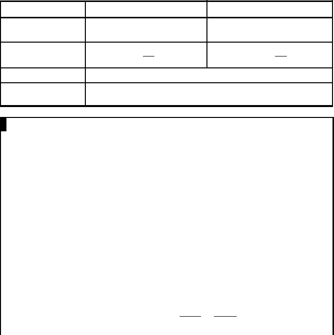
It is shown in Table I.2 that the power relationships for both star- and delta-
connected loads are equal.
Table I.2 Power relationships for star- and delta-connected loads
Load Star connected Delta connected
Current and voltage
relationship
V
L
¼
ffiffiffi
3
p
V
p
and I
L
¼ I
p
V
L
¼ V
p
and I
L
¼
ffiffiffi
3
p
I
p
Apparent power (VA) S ¼ 3V
p
I
p
¼ 3
V
L
ffiffiffi
3
p
I
L
¼
ffiffiffi
3
p
V
L
I
L
S ¼3V
p
I
p
¼3V
L
I
L
ffiffiffi
3
p
¼
ffiffiffi
3
p
V
L
I
L
Active power (kW)
P ¼ 3V
p
I
p
cos f ¼
ffiffiffi
3
p
V
L
I
L
cos f
Reactive power
(kVAr)
Q ¼ 3V
p
I
p
sin f ¼
ffiffiffi
3
p
V
L
I
L
sin f
EXAMPLE I.5
A three-phase, wye-connected generator is driven from a water turbine that
produces 15 kW mechanical shaft power . It is connected to a 500 V (V
L
),
three-phase, 60 Hz supply. The generator has an efficiency of 95% and
operates at a power factor of 0.85 lagging (exporting VArs). Calculate
(a) The output apparent power and hence the current in the connecting
circuit
(b) The active and reactive components of the current
(c) The reactive power
Answer:
(a) Output power = input power efficiency = 15 0.95 = 14.25 kW
Apparent power, S ¼
ffiffiffi
3
p
V
L
I
L
Active power, P ¼
ffiffiffi
3
p
V
L
I
L
cos f ¼ S cos f
Therefore, output apparent power ¼
P
cos f
¼
14:25
0:85
¼ 16 :76 kVA
200 Distributed generation
(b) The line current, I
L
¼
P
ffiffiffi
3
p
V
L
cos f
¼
14:25 10
3
ffiffiffi
3
p
500 0:85
¼ 19:36 A
Active componen t of the current = I
L
cos f ¼ 19:36 0:85 ¼ 16:45 A
Reactive component of the current = I
L
sin f ¼ 19:36 sinðcos
1
0:85Þ¼
10:2A
(c) Reactive power, Q ¼
ffiffiffi
3
p
V
L
I
L
sin f ¼
ffiffiffi
3
p
500 10:2 ¼ 8:83 kVAr
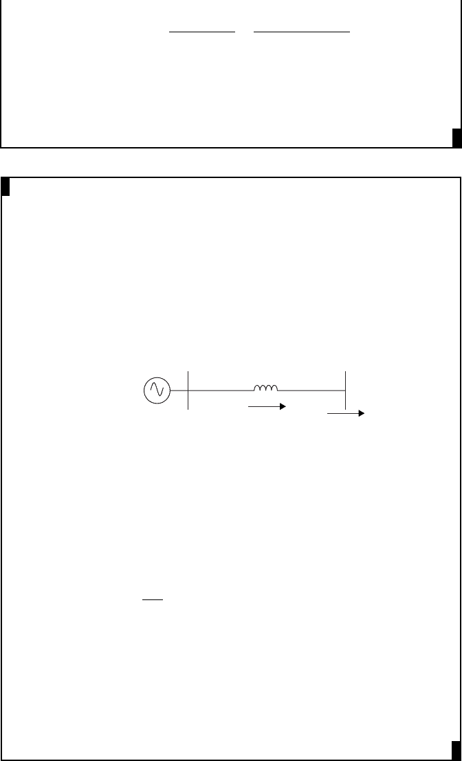
EXAMPLE I.6
A 60 Hz, wye-connected synchronous generator has a 0.5 W/phase synchro-
nous reactance and a negligible armature resistance. It is connected to a three-
phase 690 V (V
L
) system and is exporting 300 kW at a power factor of 0.85
lagging. Calculate the line current, the internal voltage and the power angle
of the generator.
Answer:
E
690 V
jX
S
I
L
Generator
300 kW
P ¼
ffiffiffi
3
p
V
L
I
L
cos f
300 10
3
¼
ffiffiffi
3
p
690 I
L
0:85
Therefore, the magnitude of the line current = I
L
¼ 295: 32 A
The angle of the line current = cos
1
0:85 ¼ 31:79
As the power factor is lagging I
L
¼ 295:32ff31:8
From the figure, assuming that 690 V bus voltage is the reference phasor:
E ¼ I
L
jX
s
þ
690
ffiffiffi
3
p
ff0
¼ 295: 32ff32:8
j0:5 þ 398:37
¼ 147: 66ff57:2
þ 398:37
¼ 80 þ j124 :12 þ 398:37
¼ 494: 2ff14:55
V
Internal voltage = 494.2 V
Power angle = 14.55
AC electrical systems 201
I.13 Problems
1. If v ¼ 10 sinðwt þ p=3Þ and i ¼ 2 sinðwt p=6Þ, find (a) the rms value of
voltage and current, (b) the phasor expression in polar form and (c) phase shift
between the current and voltage.
(Answers: (a) 7.07 V, 1.41 A; (b) 7:07ff60
,1:41ff30
and
(c) voltage leads the current by 90
)
2. A 60 mF loss-free capacitor is connected in parallel with a coil having an
inductance of 0.1 H and a resistance of 10 W. The network is connected across
an AC voltage V ¼ 10ff0
V at a frequency of 100 Hz. Draw the circuit and
calculate the value of the current in each branch and its phase relative to the
supply voltage. Sketch the calculated currents on a phasor diagram.
(Answers: Current through: capacitor 0:377 ff90
, coil 0:157 ff81
)
3. A load having a series connected resistor of 5 W and a reactor of 2 W is
connected across a 240 V AC supply.
(a) Find the active and reactive power consumption of the load and its power
factor.
(b) What is the value of power factor correction capacitor in Farad required
to improve the power factor to 0.95?
(Answers: (a) P = 9.93 kW, Q = 3.97 kVAr and power factor = 0.93;
(b) 0.26 F)
4. A star-connected load having 10 W resistance per phase is connected to a
three-phase 400 V supply. Calculate the current and power drawn by the load.
(Answers: I = 23.09 A; P = 5.33 kW)
5. A balanced delta-connected load of pure resistance of 10 W per phase is
connected in parallel with a balanced star-connected load having impedance
5 þ j2 W per phase. Both loads are connected to a 400 V three-phase supply.
Calculate the current drawn by each load and hence calculate the total current
drawn by the loads.
(Answers: current drawn by: delta load = 69:28ff0
,
star load = 42:88ff21:8
, total load = 110:26ff8:3
)
I.14 Further reading
1. Hughes E., Hiley J., Brown K., McKenzie-Smith I. Electrical and Electronic
Technology. Prentice Hall; 2008.
2. Grainger J.J., Stevenson W.D. Power System Analysis. McGraw-Hill; 1994.
3. Walls R., Johnston W. Introduction to Circuit Analysis. West Publishing
Company; 1992.
202 Distributed generation
Tutorial II
AC machines
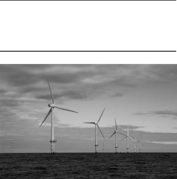
North Hoyle Offshore Wind Farm (60 MW)
This was the UK’s first major offshore wind farm and is located 4–5 miles off the
North Wales coast. Each turbine is 2 MW [RWE npower renewables]
II.1 Introduction
AC electrical machines can act as generators to convert mechanical energy into
electrical energy or motors to convert electrical energy into mechanical energy. For
example, in a hydro power station, the kinetic and potential energy in the water are
converted into mechanical rotational energy by the turbine and then into electricity
by a generator. On the other hand, an AC motor in a factory provides mechanical
energy when supplied with AC. In principle, an electrical machine of the same
construction can be used as either a motor or a generator.
There are two major types of AC machine, synchronous and asynchronous
(sometimes known as induction machines). In a synchronous machine, the rotor is
supplied by DC or has permanent magnets mounted on it. The stator carries a three-
phase winding. In an induction machine, both rotor and stator carry three-phase
windings.
II.2 Synchronous machines
II.2.1 Construction and operation
1. Rotor construction and its magnetic field
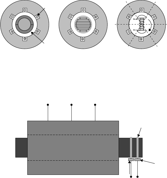
Three forms or rotor constructions are commonly used in synchronous machines:
permanent magnet, cylindrical rotor or salient pole, as shown in Figure II.1. The
rotors of the cylindrical rotor and salient pole synchronous machine carry a field
winding, which is fed from a source of DC. Even though a two-pole rotor structure
is shown in this figure, two, four or even more poles are often used.
(
a
)
Permanent ma
g
net
(
b
)
C
y
lindrical rotor
(
c
)
Salient pole
Stator
A
A
′
S
N
B
′
C
′
C
B
Armature
windings
Air gap
Axis of
phase –
A
Axis of
phase – B
Axis of
phase – C
A
A
′
S
N
B
′
C
′
C
B
A
A
′
S
N
B
′
C
′
C
B
Rotor
w
s
Figure II.1 Rotor construction of synchronous machines
In cylindrical rotor and salient pole machines, the rotor is fed with DC
through slip rings, as shown in Figure II.2.
A
B
C
⫹V
f
⫺
I
f
Three-phase AC
Slip rings
Brushes
Figure II.2 Schematic representation of a synchronous machine
204 Distributed generation
The DC on the rotor circuit (or the permanent magnets) produces a mag-
netic field, f
Rotor
, that is fixed to the rotor. As the rotor rotates at synchronous
speed (w
s
), the rotor magnetic field also rotates at the same speed.
2. Stator construction and its magnetic field
Figure II.1 also shows the stator of an AC machine. The stator core consists of
slotted ring shape laminations that are stacked and bolted together to form a
cylindrical core. The slots on this cylindrical structure carry the armature
winding. Even though only three armature winding s (A–A
0
, B–B
0
and C–C
0
)
are shown in Figure II.1 for simplicity, in a real machine the stator has several
armature coils in each phase.
When the rotor rotates, the magnetic field produced by the field winding
sweeps the three-phase armature windings. This in turn induces three voltages
in three windings, A–A
0
, B–B
0
and C–C
0
(initially assumed to be open circuit),
which are displaced by 120
. At the position shown in Figure II.1(c), the
induced voltage of the A phase is at its positive maximum and as the rotor
rotates its magnitude reduces. Once the rotor rotates by 180
the induced
voltage comes to its negative maximum. Hence, the frequency of the induced
voltage is directly proportional to the speed of rotation of the ro tor and is given
by f = w
s
/2p.
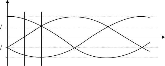
If the armature windings are connected to a balanced three-phase load, the
resulting three-phase currents are also displaced by 120
as shown in Figure II.3.
t 0 t
1
t
2
A
B
C
I
m
I
m
2
I
m
2
I
m
Time
Current
Figure II.3 Three-phase currents (t
1
= p/6w and t
2
= p/3w)
When t = 0 (Figure II.3) the current in phase A is I
m
and the currents in phases
B and C are equal to (I
m
/2). The currents in phases A, B and C produce compo-
nents of the stator magnetic field, f
A
, f
B
and f
C
. The magnitudes of these flux
components are proportional to the number of ampere-turns, NI
m
,NI
m
/2 and NI
m
/2
(where N is the effective number of turns of each phase of the stator winding) and act
along the axis of phases A, B and C (see Figures II.1(c) and II.4). These three
magnetic fields combine and produce a resultant stator magnetic field, f
Stator
,att =0
as shown in Figure II.4. The distribution of this flux in the air gap is also shown in
AC machines 205
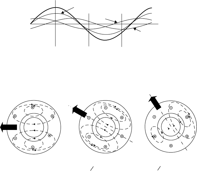
Figure II.5(a). Similarly, the resultant magnetic fields produced by the stator
current at t = t
1
and t
2
are shown in Figure II.5(b) and (c).
Axis of A
phase
Axis of B
phase
Axis of C
phase
A phase flux (
fA)
f
B
f
C
f
Stato
r
Figure II.4 Resultant stator magnetic field in the air gap at t = 0 (The x axis
shows the air gap, around the circumference of the machine.)
A
A
′
B
C
′
B
′
(a) At t = 0
(0 rad rotation)
6
(b) At t = t
1
(π rad rotation)
3
(c) At t = t
2
(π rad rotation)
A
A
′
B
′
C
′
C
B
A
A
′
B
′
C
′
C
C
B
Figure II.5 Illustration of the rotating stator magnetic field
During the time t
1
=(p/6w
s
), the flux waveform has moved by p/6. This is the
speed of the stator magnetic field and is equal to synchronous speed. In normal
operation the rotor, and hence the field winding, rotates synchronously with the
flux developed by the stator. The relative angle between the rotor flux axis and the
stator field, the rotor angle (sometimes known as the load angle), is determined by
the torque applied to the shaft.
II.2.2 Electrical and mechanical angle
In the case of a two-pole synchronous machine, for 180
of rotation of the rotor the
induced voltage changes by half a cycle or 180
electrical (P radians). Now con-
sider the four-pole machine shown in Figure II.6. At the rotor position shown, the
A phase induced voltage is at positive maximum. Once the rotor rotates by 90
,a
south pole comes immediately below the A phase and the induced voltage becomes
negative maximum. Hence, a 90
mechanical rotation corresponds to 180
electrical
variation in the induced voltage.
206 Distributed generation