Jenkins N., Strbac G., Ekanayake J. Distributed Generation
Подождите немного. Документ загружается.

The form V
j
¼ Vfff is called the polar form of phasor V
j
and V
j
¼ V½cos f þ
j sin f is called the rectangular or Cartesian form of phasor V
j
.
1
In this book,
phasors are given in bold ðV
j
Þ and their magnitude is given normal type (not bold)
ðV ¼jV
j
jÞ. The diagram representing phasor V
j
(by its magnitude V and angle f)
is shown in Figure I.4 (drawn using rms quantities) and is called the phasor diagram.
I.5 Resistors, inductors and capacitors on AC circuits
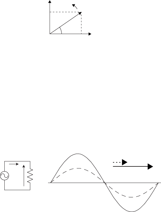
I.5.1 Resistance in an AC circuit
Figure I.5 shows a resistor, R, connected across an AC voltage source vðtÞ¼
V
m
sinðwtÞ. The current through the resistor is determined by Ohm’s law and is
given by: iðtÞ¼V
m
=R sinðwt Þ. If the voltage phasor is V and current phasor is I,
then V ¼ IR.
A
C
I
V
R
V
I
v
i
t
Figure I.5 Time domain and phasor representation of voltag e and current in R
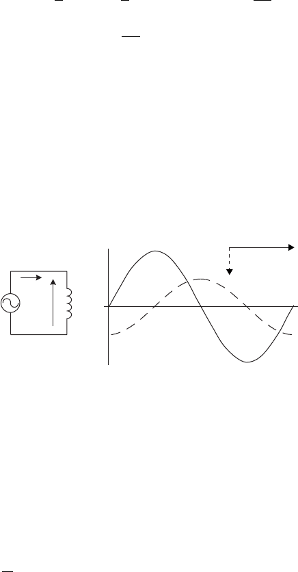
I.5.2 Inductance in an AC circuit
The relationship between current and voltage for a pure inductance is v ¼ Lðdi=dtÞ.
For an applied voltage v as shown in Figure I.6, the current can be obtained by
V
j
= V∠f
Vcosf
Vsinf
Re
I
m
f
w
Figure I.4 Phasor diagram of V
j
(shown on real and imaginary axes)
1
j is the imaginary operator ð
ffiffiffiffiffiffiffi
1
p
Þ and in polar form j ¼ 1ff90
.
AC electrical systems 187
integrating the voltage:
iðtÞ¼
1
L
Z
t
0
vdt ¼
1
L
Z
t
0
V
m
sinðwtÞdt ¼
V
m
wL
cos wt
¼
V
m
wL
sinðwt p=2Þ
The voltage and current waveforms for the inductive circuit are shown in
Figure I.6. The current through the inductor lags the voltage by 90
. If the voltage
phasor is V and current phasor is I, then V=I ¼ wLff90
¼ jwL. The quantity jwLis
the impedance of the inductor and has the unit of ohms. The magnitude of the
impedance, i.e. X
L
¼ wL, is referred to as inductive reactance, also with units of
ohms. When the inductor is represented by its reactance, then Ohm’s law can be
applied to the phasors of voltage and current.
V
I
v
i
t
A
C
I
V
L
Figure I.6 Time domain and phasor representation of voltage and current in L
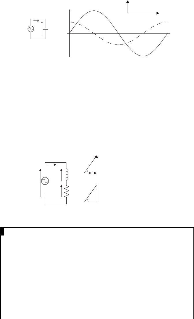
I.5.3 Capacitance in an AC circuit
The relationship between current and voltage for a pure capacitance is i ¼ Cðdv=
dtÞ. As shown in Figure I.7, if a sinusoidal vol tage v is applied across the capacitor,
the current through the capacitor is given by:
iðtÞ¼C
d
dt
ðV
m
sin wtÞ
¼ wCV
m
cos wt
¼ wCV
m
sinðwt þðp=2ÞÞ
ðI:4Þ
188 Distributed generation
AC
I
V
C
V
I
v
i
t
Figure I.7 Time domain and phasor representation of voltage and current in C
If the voltage phasor is V and the current phasor is I, V=I ¼ð1=wCÞff 90
¼
1=jwC. The quantity 1=jwC is the impedance of the capacitor and has the unit of
ohms. The magnitude of the impedance, i.e. X
C
¼ 1=wC, is referred to as the
capacitive reactance, again with the unit of ohms. When the capacitor is represented
by its reactance, then Ohm’s law can be applied to the phasors of voltage and current.
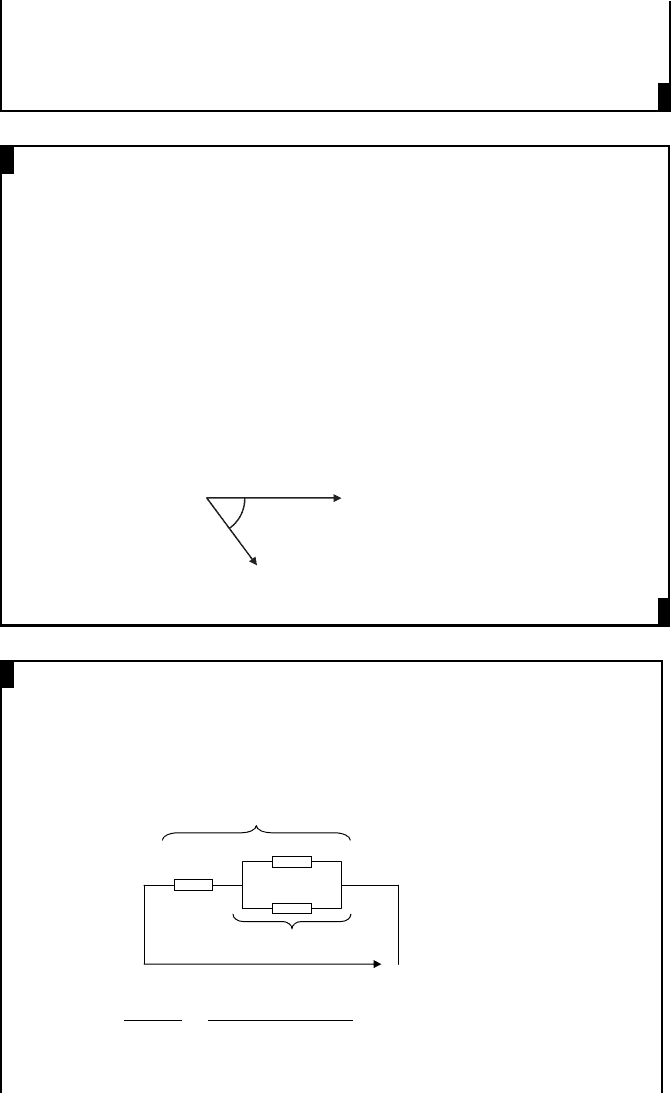
I.5.4 R–L in an AC circuit
A series R–L circuit is shown in Figure I.8. The current through the circuit is limited
by the impedance of the circuit, given by Z ¼R þ jX
L
. The phase angle between the
applied voltage and current is given by tan
1
ðwL=RÞ.
V
I
R
L
V
R
= IR
V
L
= jI X
L
V = V
R
+ V
L
V = I(R + j X
L
) = IZ
I
V
X
L
=
ω
L
Z
R
V
L
V
R
V
R
V
L
f
f
Figure I.8 Series R–L circuit, phasor and impedance diagrams
EXAMPLE I.1
Calculate the resistance and inductance or capacitance in series for each of
the following impedances, assuming the frequency to be 60 Hz:
(a) 50 þ j30 W
(b) 40ff60
W
Answer:
(a) 50 þ j30 W = R þ jwL
Comparing: R ¼ 50 W and wL ¼ 30 W
When the frequency is 60 Hz: w ¼ 2pf ¼ 2p 60 ¼ 377 rad=s
Therefore, L ¼ 30=377 ¼ 79:6 10
3
H ¼ 79:6mH
AC electrical systems 189
(b) 40ff60
¼ 20 j34:64 W ¼ R þð1= jwCÞ¼R ðj=wCÞ
Comparing: R ¼ 20 W and 1=wC ¼ 34:64 W
Since w ¼ 377 rad=s, C ¼ 1=ð377 34:64Þ¼76 :6 10
6
F ¼ 76:6 mF
EXAMPLE I.2
A voltage vðtÞ¼170 sinð377tÞ volts is applied acros s a winding having a
resistance of 2 W and an inductance of 0.01 H. Write down an expression for
the rms values of the voltage and current phasors in rectangular notation.
Draw the phasor diagram.
Answer:
R ¼ 2 W and L ¼ 0:01 H
Since the voltage is vðtÞ¼170 sinð377tÞ: w ¼ 377 rad=s
Voltage as a phasor = ð170=
ffiffiffiffiffi
2Þ
p
ff0
¼ 120: 2ff0
¼ 120: 2þj0V
wL ¼ 377 0:01 ¼ 3:77 W
Impedance of the winding = 2 þ j 3: 77 W ¼ 4:27ff62:05
W
Current as a phasor ¼ 120:2ff0
=4:27ff62:05
¼ 28 :13ff62:05
¼ 13 :18
j24.85 A
V = 120.2 ∠0°
V
I = 28.13 ∠62° V
Phasor dia
g
ram
62°
EXAMPLE I.3
An impedance of 2 þ j6 W is connected in series with two impedances of 10 þj4
W and 12 j8 W, which are in parallel. Calculate the magnitude and the phase
angle of the main current when the combined circuit is supplied at 200 V.
Answer:
Z
1
= 2 + j6Ω
Z
2
= 10 + j4Ω
Z
3
= 12 − j8Ω
200 V
Z
1
Z
3
Z
2
Z
p
Z
t
Z
p
¼
Z
2
Z
3
Z
2
þZ
3
¼
½10 þ j4½12 j8
10 þ j4 þ 12 j8
¼ 6:95 j0: 19
190 Distributed generation
Z
t
¼ Z
1
þZ
p
¼ 8:95 þ j5: 81 ¼ 10:67ff33
I ¼
200
10:67ff33
¼ 18 :74ff33
Magnitude of the current = 18.74 A
Angle of the current = 33
and lags the voltage
I.6 Power in AC circuits
Instantaneous power in an AC circuit is the product of instantaneous voltage and
current.
For a pure resistor vðtÞ¼R iðtÞ and the instantaneou s power, pðtÞ, is:
pðtÞ¼vðtÞiðtÞ¼vðtÞ
2
=R ¼ iðtÞ
2
R ðI:5Þ
If vðtÞ¼V
m
sin wt, the average power dissipation in the resistor is given by:
P
ave
¼
1
T
Z
T
0
pðtÞdt ¼
V
2
m
R T
Z
T
0
sin
2
wt dt ¼
V
2
m
R T
Z
T
0
1 cosð2wtÞ
2
dt
¼
V
2
m
2R
¼
V
2
R
¼ I
2
R ðI:6Þ
where V and I are rms quantities.
For a pure inductor vðtÞ¼LðdiðtÞ=dtÞ and the instantaneous power is:
pðtÞ¼vðtÞiðtÞ¼L iðtÞ
d
dt
iðtÞðI:7Þ
If iðtÞ¼I
m
sin wt, the average power dissipation in the inductor is given by:
P
ave
¼
wLI
2
m
T
Z
T
0
sin wt cos wt dt ¼ 0 ðI:8Þ
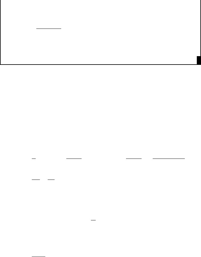
Figure I.9 shows the instantaneous power associated with two circuits one having
a pure resistor and the other having a pure inductor. In the circuit having a resistor, the
instantaneous power varies at double the frequency of the voltage and current with a
positive average value. The power of this circuit converts electrical energy into heat
and is called active power. In the circuit having an inductor, the instantaneous power
alternates with a zero average value. The power associated with energy oscillating in
and out of an inductor is called reactive power. The active power is measured in watt or
kilowatt, and the reactive power is measured in Var or kiloVar.
AC electrical systems 191
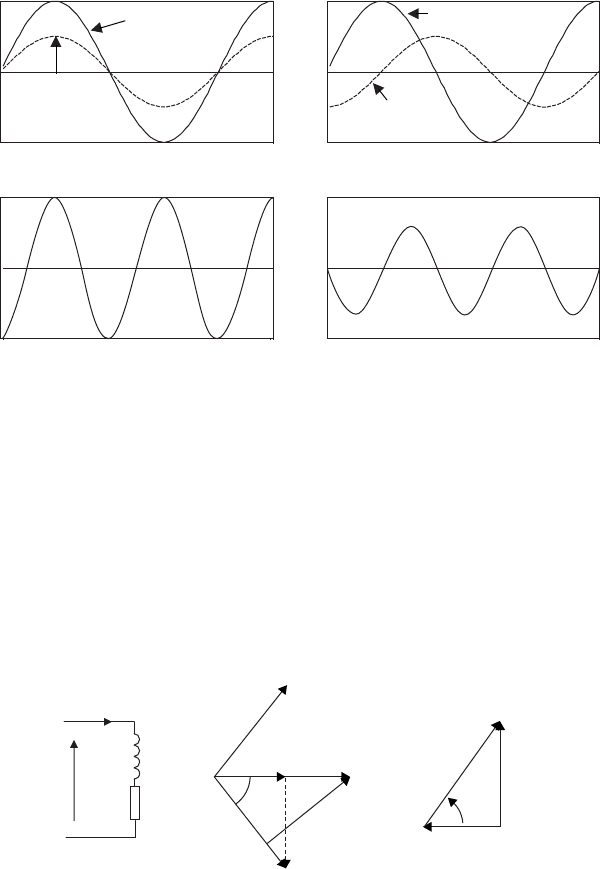
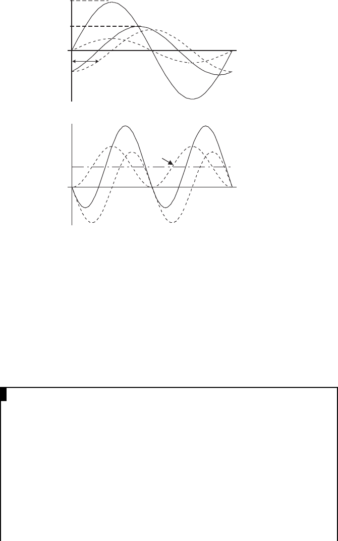
Now consider a resistor and an inductor connected across an AC voltage
source as shown in Figure I.10(a). The phasor diagram is shown in Figure I.10(b).
The instantaneous current can now be divided into two components: a component
in phase with the voltage, I
P
(which causes the active power), and a component
having 90
phase shift, I
Q
(which causes the reactive power). The instantaneous
power associated with this circuit and its active and reactive power components are
shown in Figure I.11.
From Figure I.10(c):
Active power; P ¼ V I
P
¼ VI cos f ðWÞðI:9Þ
Reactive power; Q ¼ V I
Q
¼ VI sin f ðVArÞðI:10Þ
0 0
0
Time
(
a
)
For a circuit with a pure resistor
(
b
)
For a circuit with a pure inductor
Instantaneous power
0
Time
Instantaneous power
Voltage
Voltage
Current
Current
Figure I.9 Instantaneous power for a circuit with a resistor and an inductor
(
c
)(
b
)(
a
)
L
R
V
I
I
R
IwL
V
I
φ
I
P
I
Q
I*
Q
P
S = VI*
f
Figure I.10 An R–L circuit (inductive load)
192 Distributed generation
It is conventional to define S, the apparent power, as VI* (see Figure I.10(b)
where I* is shown). In Figure I.10(c), S ¼
ffiffiffiffiffiffiffiffiffiffiffiffiffiffiffiffi
P
2
þ Q
2
p
¼ VI
. S is measured in volt-
ampere or kilovolt-ampere. The cosine of the angle f (cos f) is called the power
factor of the circuit.
Most industrial and large commercial electricity consumers have pre-
dominantly inductive loads. For a given applied voltage and real power load,
the current drawn is high if the power factor is low. This in turn increases the size of
the distribution cables required both within the consumer premises and on the uti-
lity side, the size of the transformers and losses in cables and transformers.
P
Active power
component
=
i
P
Reactive power
component =
i
Q
Instantaneous
power =
i
I
m
V
m
i
i
Q
i
P
i
P
= Active current component
i
Q
= Reactive current component
φ
wt
wt
Figure I.11 Active and reactive power associated with an inductive load
EXAMPLE I.4
A single-phase motor of 10 kW operates at a power factor of 0.8 lagging
when connected to a 230 V, 50 Hz supply. It is proposed to improve the
power factor to 0.9 lagging by connecting a capacitor across the load. Cal-
culate the kVAr rating of the capacitor.
Answer:
As shown in Figure I.7, for a capacitor f ¼ 90
and therefore from (I.9) and
(I.10), P ¼ 0 and Q ¼ VI; that is a capacitor acts as a source of reactive power.
Therefore, if a capacitor is connected across the motor, a part of the reactive
power drawn by the motor is supplied by the capacitor, thus reducing reactive
power drawn from the AC mains. This is called power factor correction.
AC electrical systems 193
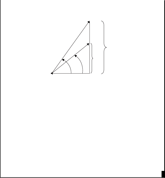
Power factor angle before correcting the power factor = cos
–1
0.8 = 36.87
Power factor angle after correcting the power factor = cos
1
0:9 ¼ 25:84
P = 10 kW
Q
1
36.87°
S = VI*
25.84º
Q
2
Reactive power drawn from the supply before power factor correction
2
Q
1
¼ 10 tan 36:87
¼ 7:5 kVAr
Reactive power drawn from the supply after power factor correction
Q
2
¼ 10 tan 25:84
¼ 4:84 kVAr
That is a capacitor connected across the motor should supply the reactive
power of ðQ
1
Q
2
Þ locally. Thus, the kVAr rating of the capacitor
¼ Q
1
Q
2
¼ 7:5 4:84 ¼ 2:66 kVAr
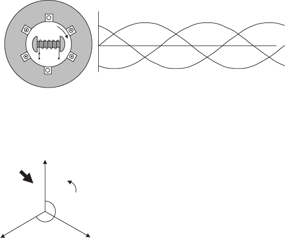
I.7 Generation of three-phase voltages
If three coils, shown in Figure I.12(a), which are physically displaced 120
are
supplied with a three-phase AC voltage, then the resultant voltage in each coil is
displaced in time by 120
as shown in Figure I.12(b).
In a three-phase system, the voltage in B phase lags the voltage in A phase by
120
(2p
=
3 rad) and the voltage in C phase lags the voltage in A phase by 240
(4p
=
3 rad). The three-phase system can be represented by the phasor diagram of
Figure I.13. The corresponding mathematical description of the three-phase system
is also given in that figure.
2
From (I.9) and (I.10), Q = p tan f.
194 Distributed generation
v
A
(t) = v
A
= V
m
sinwt
v
B
= V
m
sin (wt − 2p/3)
v
C
= V
m
sin (wt − 4p/3)
V
A
= V ∠ 0°
V
B
= V ∠ − 120°
V
C
= V ∠ − 240°
Phasor dia
g
ram Mathematical description Phasor description
V
A
V
B
V
C
120°
120°
w
Stationary
observer
Figure I.13 Different descriptions of the three-phase system (Instantaneous
values are given in the form of v (not in the form v(t)) in the
subsequent sections)
A stationary observer sees the phasor diagram in Figure I.13 will see coils A, B
and C passing him in time in that order. Therefore, the phase sequence of the supply
is ABC.
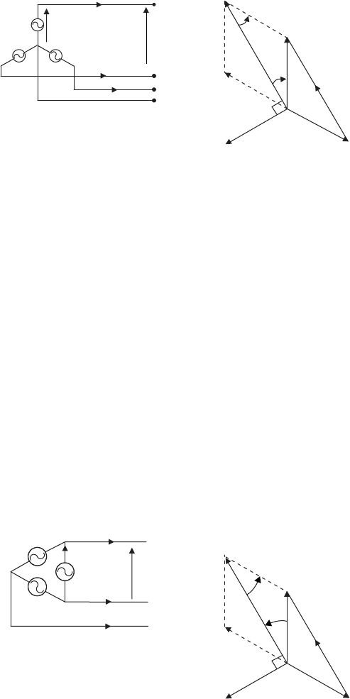
I.8 Connection of three-phase windings
The windings in the three phases of Figure I.12(a) are always connected together so
that three-phase voltages are carried on three or four wires. Three windings can be
connected in star (wye) or delta.
I.8.1 Star connection
A star connection can be obtained by connecting terminals A
0
,B
0
and C
0
(see Figure
I.12(a)) together to form a neutral point (N) as shown in Figure I.14. From this
connection, three or four wires can be taken to the load thus forming a three-phase,
star-connected, three-wire or four-wire system. Two voltages can be defined: the
phase voltage (the voltage between the neutral and any terminal, V
AN
, V
BN
and
V
CN
) and the line voltage (the voltage between any two terminals, V
AB
, V
BC
and V
CA
). In the star connection, the phase current and line current are the same and
denoted by I
A
, I
B
and I
C
in Figure I.14.
(
a
)(
b
)
B
C
A
A
A′
B′
B
w
s
C
C′
Figure I.12 Three-phase voltages
AC electrical systems 195
V
AN
= V
A
− V
N
V
AB
= V
AN
− V
BN
30°
30°
V
AN
V
BN
V
CN
N
–V
B
V
AB
V
AB
V
AN
A
B
N
V
AB
C
I
B
I
C
I
A
Figure I.14 Star-connected three-phase source
The phasor diagram in Figure I.14 shows the line voltage V
AB
. Assuming that
the rms value of the magnitude of phase voltages V
AN
, V
BN
and V
CN
is V
p
and the
rms value of the magnitude of line voltages V
AB
, V
BC
, V
CA
is V
L
, then from the
phasor diagram:
V
AB
¼ V
AN
jj
cos30
þ V
BN
jj
cos30
V
L
¼ 2 V
p
cos30
V
L
¼
ffiffiffi
3
p
V
p
ðI:11Þ
For example, if the phase voltage is 230 V, then the line voltage is
ffiffiffi
3
p
230 ¼400V.
I.8.2 Delta connection
By connecting terminal A
0
to B, B
0
to C and C
0
to A, the delta connection can be
formed as shown in Figure I.15. In the delta connection, there is no neutral, and line
voltages and phase voltages are the same. If V
AB
þV
BC
þV
CA
¼ 0, there is no
circulating current in the delta loop.
30º
30º
I
A
I
B
I
C
N
–I
B
I
AB
I
RY
B
A
C
I
AB
I
A
V
AB
I
B
I
C
If the three-phase voltages are
balanced:
v
AB
= V
m
sinwt
v
BC
= V
m
sin
(
wt − 2
π/
3
)
v
CA
= V
m
sin
(
wt − 4
π/
3
)
Figure I.15 Delta-connected three-phase system
196 Distributed generation