Jenkins N., Strbac G., Ekanayake J. Distributed Generation
Подождите немного. Документ загружается.

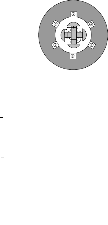
A
A
′
SS
N
N
B
′
C
′
C
B
Figure II.6 Four-pole synchronous machine
In general if there are p number of poles, the relationship between the electrical
(q
e
) and mechanical (q
m
) angles is given by:
q
e
¼
p
2
q
m
ðII:1Þ
By dividing both sides of (II.1) by time, one can obtain a relationship between
the mechanical and electrical rotational speeds:
w
e
¼
p
2
w
m
ðII:2Þ
Assuming that the torque applied on the rotor by a turbine is T
m
and electro-
magnetic torque is T
e
, then from power balance:
T
m
w
m
¼ T
e
w
e
ðII:3Þ
From (II.2) and (II.3):
T
m
¼
p
2
T
e
ðII:4Þ
Direct-drive wind turbine generators are directly connected to the aerodynamic
rotor. Hence, they have large number of poles and operate a low mechanical rota-
tional speed but with high mechanical torque.
II.2.3 Equivalent circuit
To investigate how a synchronous generator will behave on the power system, a
simple model is required. When the stator is open circuit, the stator terminal vol-
tage is equal to the internal voltage, E
F
, as shown in Figure II.7.
When the armature windings are connected to a three-phase load, the magnetic
field produced by the armature currents interacts with the rotor magnetic field, f
Rotor
.
The effect of f
Stator
on f
Rotor
is called armature reaction. The armature reaction is
normally represented by a reactance in the synchronous machine equivalent circuit.
AC machines 207
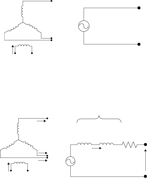
Further, a part of the flux produced by the rotor is not linked with the stator and that
component is called leakage flux. This component is also represented by a reactance.
Finally voltage drop across the stator resistance is also taken into account when
developing the equivalent circuit. The equivalent circuit is shown in Figure II.8.
(
b
)
Equivalent circuit
(
a
)
S
y
nchronous machine on load
Armature
reaction
I
V
E
F
jX
A
jX
I
R
Stator
leakage
reactance
Stator
reactance
Synchronous
reactance (X
s
)
A
C
B
V
f
Rotor
I
f
I
A
I
B
I
C
Stator
(Armature)
Figure II.8 Synchronous machine equivalent circuit
Generally for synchronous generators, X
s
is much greater than R and therefore
R is neglected. From Figure II.8(b), it may be seen that:
V ¼ E
F
jIX
s
ðII:5Þ
where V = terminal voltage, E
F
= internal voltage (function of the field current),
X
s
= synchronous reactance.
For a small distributed generator, the terminal voltage is held almost constant
by the network and so phasor diagrams may be developed (Figure II.9) that illustrate
the operation of a synchronous generator on to a fixed voltage (or infinite busbar).
A
C
B
V
f
Rotor
I
f
Stator
(Armature)
E
F
Figure II.7 Synchronous machine on open circuit
208 Distributed generation
The power factor of the power delivered to the network is simply cos f, while the
rotor or load angle (the angle by which the rotor is in advance of the stator voltage) is
given by d.
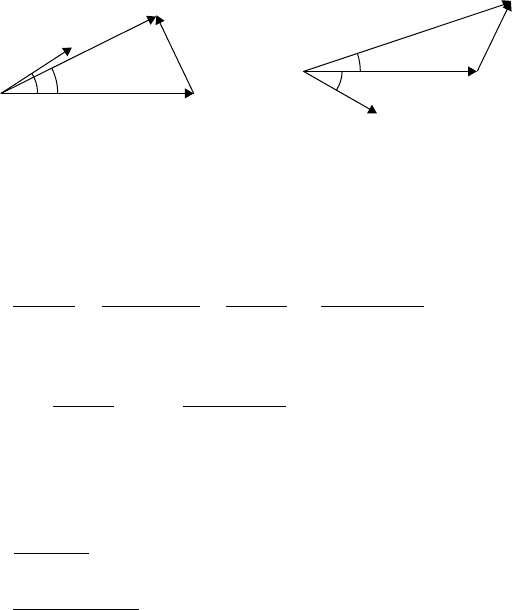
(
a
)
Under-excited mode
jIX
s
jIX
s
E
F
E
F
I
I
V
V
f
f
d
d
(
b
)
Over-excited mode
Figure II.9 Phasor diagram of synchronous generator (f: power factor angle,
d: rotor angle)
From Figure II.9(b):
I ¼
E
F
V
jX
s
¼
E
F
ffd Vff0
jX
s
¼
E
F
sin d
X
s
j
E
F
cos d V
X
s
S ¼VI
¼ V
E
F
sin d
X
s
þ jV
E
F
cos d V
X
s
¼ P þ jQ
Therefore:
P ¼
E
F
V sin d
X
s
ðII:6Þ
Q ¼
E
F
V cos d V
2
X
s
ðII:7Þ
In normal operation, the rotor angle d is usually less than 30
. Hence the real
power output (P) is proportional to the rotor angle (d). Increasing the torque on the
rotor shaft increases the rotor angle (d) and results in more active power exported to
the network, as shown in (II.6). As the rotor angle is a function of the load on the
rotor shaft, it is also known as the load angle.
Again with a rotor angle of less than 30
, cos (d) remains approximately
constant. Increasing the field current and hence increasing the magnitude of E
F
results in export of reactive power, as shown in (II.7).
The phasor diagrams of Figure II.9 show two different values of excitation
(determined by the magnitude of E
F
).
1. Under-excited E
F
< V
This gives a leading power factor (using a generator convention and the
direction of I as shown in Figure II.8(b)), importing reactive power.
AC machines 209
2. Over-excited: E
F
> V
This gives a lagging power factor (using a generator convention and the
direction of I as shown in Figure II.8(b)), exporting reactive power.
It may be noted that if the direction of the definition of the current I is reversed,
and the machine considered as a motor rather than a generator, then an under-excited
motor has a lagging power factor and an over-excited motor has a leading power
factor. Of course, if torque is still applied to the shaft, then active power will be
exported to the network and if E
F
> V then reactive power will still be exported
irrespective of whether the same machine is called a motor or a generator. Therefore,
it is often helpful to consider export/import of real and reactive power than leading/
lagging power factors that rely on the definition of the direction of the current flow.
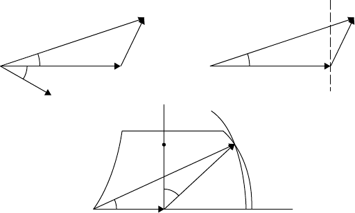
II.2.4 Operating chart of a synchronous generator
The operating chart of a synchronous generator is formed directly from the phasor
diagram of Figure II.9. The phasor diagram is simply scaled by multiplying by V/X
s
,
which is a constant, to give the phasor diagram of Figure II.10. The locus of the new
phasor VI then describes the operation of the generator. Various limits are applied to
account: (1) for the maximum power available from the prime mover, (2) the max-
imum current rating of the stator, (3) the maximum excitation and (4) the minimum
excitation for stability and/or stator end winding heating. These limits then form the
boundaries of the region within which a synchronous generator may operate. In
practice, there may be additional limits including a minimum power requirement of
the prime mover and the effect of the reactance of the generator transformer.
jIX
s
E
F
I
V
V
2
/X
s
E
F
V/X
s
VI
VI
f
f
d
d
d
Under-excited
absorbin
g
VArs
Over-excited
exportin
g
VArs
P
OQ
Prime mover limit
Stator limit
Rotor limit
Under-excitation
limit
x
z
y
.
.
Figure II.10 Operating chart of a cylindrical pole synchronous generator
connected to an infinite bus
The operating chart illustrates that a synchronous generator connected to an
infinite busbar of fixed voltage and frequency has essentially independent control
over real and reactive power. Real power is varied by adjusting the torque on the
210 Distributed generation
generator shaft and hence the rotor angle, while reactive power is adjusted by varying
the field current and hence the magnitude of E
F
. For example at point (x) both real
and reactive power are exported to the network, at (y) rather more real power is being
exported at unity power factor, while at (z) real power is exported and reactive power
is imported.
II.2.5 Excitation systems
The performance of a synchronous generator is strongly influenced by its excitation
system particularly its transient and dynamic stability, and the ability of the gen-
erator to deliver sustained fault current.
On some older generator s, a DC generator, with a commutator, was used to
provide the field current, wh ich was then fed to the main field via slip rings on the
rotor. Equipment of this type can still be found in se rvice, although often with mod ern
AVRs replacing the rather simple voltage regulators that were used to control the
field of the DC generator and hence the main excitation current. However, more
modern excitation systems are generally of two types: (1) brushless or (2) static.
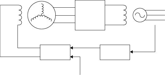
Figure II.11 is a schematic representation of a brushless excitation system. The
exciter is simply an alternator, much smaller than the main generator and with a sta-
tionary field and a rotating armature. A full wave diode bridge is mounted on the
rotating shaft to rectify the three-phase output of the exciter rotor to DC for the field of
the main generator. The exciter field is controlled by the AVR that is set to control
either the generator terminal voltage or, using a power factor controller, to maintain
either a constant power factor or a defined reactive power output. Power for the exciter
may be taken either from the terminals of the main generator (self-excited) or from a
permanent magnet generator (separately excited). The permanent magnet generator is
mounted on an extension of the main generator shaft and continues to supply power as
long as the generator is rotating.
Rotating
diode
rectifier
Power factor
controller
Excitation
power supply
V, I
measurements
Exciter Generator
Three-phase
rotor
Exciter
field
AVR
Figure II.11 Brushless excitation system
Figure II.12 shows a static excitation system in which DC is supplied by a
controlled thyristor rectifier and fed to the generator field via slip rings. The power
supply for the thyristor rectifier is taken from the terminals of the generator. The
main advantage of the static exciter is improved speed of response as the field
AC machines 211
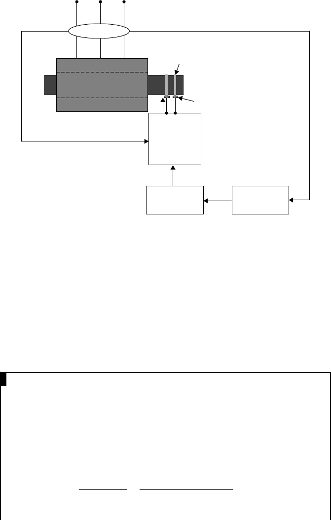
current is controlled directly by the thyristor rectifier but, of course, if the generator
terminal voltage is depressed too low then excitation power will be lost.
controled
thyristor
rectifier
Power factor
controller
Power supply
V, I
measurements
Generator
AVR
A
B
C
Three-phase AC
Slip rings
Brushes
Figure II.12 Static excitation system
In addition to the main types described, there are a large number of innovative
designs of excitation systems, which have been developed over the years particu-
larly for smaller generators. These include the use of magnetic circuits for the no-
load excitation and current transformer compounding for the additional excitation
required as current is drawn. Although such techniques may work robustly on
standalone systems, they are almost impossible to model for studies of distributed
generation schemes. For larger generators and their excitation systems the manu-
facturers are usually able to supply the so-called IEEE exciter models. These refer
to the structure of excitation system models that have been developed by the IEEE
and are included in most power system analysis programs.
EXAMPLE II.1
A 13.8 kV(V
L
), 20 MVA, 50 Hz, three-phase, star-connected synchronous
generator has a synchronous reactance of 1.5 W/phase and negligible resis-
tance. It supplies 10 MW at a power factor of 0.8 lagging (exporting VArs) to
an infinite busbar held at 13.8 kV. What is the internal voltage and power
angle of the generator?
Answer:
The line voltage of the infinite busbar is 13.8 kV and P ¼
ffiffiffi
3
p
V
L
I
L
cos f
Hence I
L
¼
P
ffiffiffi
3
p
V
L
cos f
¼
10 10
6
ffiffiffi
3
p
13:8 10
3
0:8
¼ 523 A
Angle of load current = cos
1
(0.8) = 36.87
212 Distributed generation
Since the power factor is lagging and the generator exporting VArs:
I
L
¼ 523ff36:87
From (II.5):
E
F
¼ V þ jIX
s
¼
13:8 10
3
ffiffiffi
3
p
ff0
þ 523ff36:87
j1:5
¼ 7967:4 þ 784:5ff53:13
¼ 7967:4 þ 470:7 þ j627:6
¼ 8438:1 þ j627:6
¼ 8461:4ff4:25
Therefore, the magnitude of the generator internal voltage = 8461:4
ffiffiffi
3
p
¼
14:66 kV Rotor angle = 4.25
.
EXAMPLE II.2
A 12 kV(V
L
), 120 MVA, 50 Hz, three-phase, star-connected synchronous
generator has a synchronous reactance of 0.3 W/phase and negligible resis-
tance. It is connected to an infinite busbar and supplies 60 MW at power
factor of 0.85 lagging. If the excitation of the machine is increased by 20%
and the mechanical power input by 25%, determine the subsequent rotor
angle at which the machine operates.
Answer:
The line voltage of the infinite busbar is 12 kV, and the generator supplies
60 MW at a lagging power factor of 0.8.
I
L
¼
P
ffiffiffi
3
p
V
L
cos f
¼
60 10
6
ffiffiffi
3
p
12 10
3
0:85
¼ 3396:2A
Angle of load current = cos
1
(0.85) = 31.8
Since the load is lagging: I
L
= 3396.2ff31.8
From (II.5):
E
F
¼ V þ jIX
s
¼
12 10
3
ffiffiffi
3
p
ff0
þ 3396:2ff31:8
j0:3
¼ 6928:2 þ 1018:86ff58:2
¼ 6928:2 þ 536:9 þ j865:9
¼ 7515:15ff6:6
If the efficiency of the generator is h, the input mechanical power =
60/h MW
AC machines 213
If the mechanical power is increased by 25%, the new mechanical power
input = 1.25 60/h MW
New electrical output = 1.25 (60/h) h =75MW
When the excitation increases the internal voltage by 20% and the
mechanical input is increased by 25%, from (II.6):
75 10
6
¼
1:2 7515:15 6928:2 sin d
2
0:3
sin d
2
¼ 0:36
d
2
¼ 21 :1
New rotor angle is 21.1
.
II.3 Induction machines
II.3.1 Construction and operation
The stator of an induction machine is a laminated structure (similar in construction
to a synchronous machine stator), which carries a three-phase winding and is fed
with a three-phase power supply.
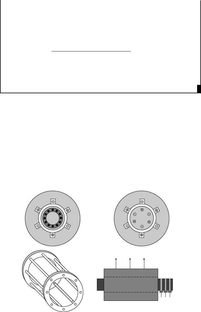
The commonly used rotor is a squirrel-cage construction as shown in Figure
II.13(a). In this rotor, solid copper or aluminium bars are embedded in a laminated
rotor structure and short circuited by two end rings (Figure II.13(a) – bottom). The
other rotor construction is called wound rotor, where the rotor carries three-phase
(
b
)
Wound-rotor induction machine
(
a
)
Squirrel-ca
g
e induction machine
A
A
′
B
′
C
′
C
B
A
A
′
B
′
C
′
C
B
a′
a
b
c
c′
b′
A
B
C
Three-phase AC
Slip rings
Brushes
abc
Rotor
terminals
Stator
terminals
Figure II.13 Induction machine construction
214 Distributed generation

windings as shown in Figure II.13(b). The terminals of the three windings, con-
nected in star or delta, are taken out through slip rings ((Figure II.13(b) –
bottom). In wound-rotor induction motors, and some variable speed wind turbines,
these windings are often short circuited through a set of resistors.
To describe the operation of the induction machine, it is easier to start with
motoring operation. When the stator winding s are connected to a three-phase sup-
ply, a rotating magnetic field is set up as described for a synchronous machine. This
rotating magnetic flux (f
Stator
) cuts the rotor conductors, which are stationary at
start-up, and induces a voltage. Since the rotor consists of three-phase windings (or
a squirrel cage that forms a three-phase winding), the induced voltage in each rotor
phase will be displaced in space by 120
. Normally in induction machines, all three
phases in the rotor are short circuited and therefore the induced voltage in the rotor
produces a circulating current. Three-phase currents flowing in the rotor will also
produce a rotating magnetic field (f
Rotor
). There will be an alignment force
between stator and rotor magnetic fields, thus creating a torque proportional to:
T / f
Stator
f
Rotor
sin q ðII:8Þ
where q is the angle between the two fluxes.
The rotor then accelerates to its running speed (w
r
) slightly less than syn-
chronous speed, w
s
. Since w
r
< w
s
, there is still relative movement between the
rotor conductors and the stator flux, thus maintaining the rotor current and flux.
The normalised value of the difference between the running speed of the rotor and
the synchronous speed is defined as the slip and given by:
s ¼
w
s
w
r
w
s
ðII:9Þ
II.3.2 Steady-state operation
An induction machine can be considered as a transformer where the stator acts as
the primary and the rotor acts as the secondary. The main difference between a
transformer and an induction machine is that the frequency of the induced voltage
on the rotor circuit will differ from the stator frequency as the rotor rotates.
When the rotor is not rotating (w
r
= 0):
The relative motio n between the rotor conductors and the st ator magnetic field is
w
s
. Assume that the rotor-induced voltage is equal to E
2
and ro tor inductance is L
2
.
As the rotor-induced voltage is proportional to the speed of rotation of the rotor
conductors with respect to the stator magnetic field:
1
E
2
/ w
s
ðII:10Þ
The frequency of E
2
is w
s
=2p ¼ f ðII:11Þ
Rotor reactance X
2
¼ 2pf L
2
ðII:12Þ
1
From Faraday’s law: E ¼Nðdf=dtÞ.Iff is sinusoidal as shown in Figure II.4, then f ¼ f
m
sin w
s
t.
Therefore, E ¼Nf
m
w
s
sin w
s
t; E / w
s
.
AC machines 215
When the rotor is rotating at w
r
:
There will be a relative motion between the rotor conductors and the stator
magnetic field equal to w
s
w
r
= sw
s
(see (II.9)). If the rotor-induced voltage
is E
r
2
:
E
r
2
/ sw
s
ðII:13Þ
The frequency of E
r
2
is sw
s
=2p ðII:14Þ
From (II.10) and (II.13), E
r
2
¼ sE
2
and from (II.11) and (II.14), the frequency
of the rotor-induced voltage when the rotor is running is sf
If the rotor reactance is X
r
2
:
X
r
2
¼ 2psf L
2
ðII:15Þ
From (II.12) and (II.15), X
r
2
¼ sX
2
.
Figure II.14 shows the transformer equivalent circuit of an induction machine
when the rotor is running with slip s.
R
1
X
1
V
1
I
1
I
0
f
R
2
sX
2
sE
2
I
2
sf
Rotor short circuited
Figure II.14 Induction machine equivalent circuit
In Figure II.14, R
1
is the stator resistance, X
1
is the stator leakage reactance,
R
2
is the rotor resistance and X
2
is the rotor leakage reactance at standstill.
From the rotor side of the equivalent circuit:
I
2
¼
sE
2
R
2
þ jsX
2
ðII:16Þ
Dividing both the numerator and denominator by s:
I
2
¼
E
2
ðR
2
=sÞþjX
2
¼
E
2
R
2
þ R
2
ðð1=sÞ1ÞþjX
2
ðII:17Þ
Now by transforming the rotor quantities into the stator and by considering
(II.17), the stator referred equivalent circuit of an induction machine is obtained.
This is the familiar (Steinmetz) induction motor equivalent circuit and is shown in
Figure II.15.
216 Distributed generation