Jenkins N., Strbac G., Ekanayake J. Distributed Generation
Подождите немного. Документ загружается.

I
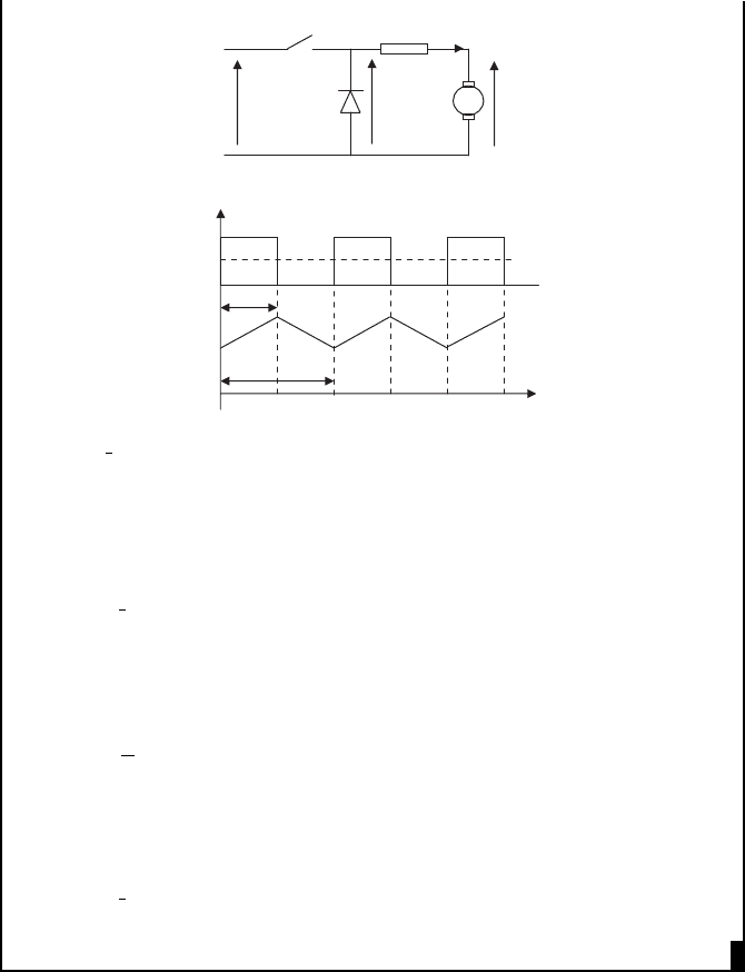
DC
Ra = 2Ω
V
DC_Ave
E
240 V
V
DC
I
DC
V
DC_Ave
240 V
T
1
T
V
DC Ave
¼ d 240 V where d is the duty ratio of the switch, which is
given by T
1
/T.
As the induced voltage is proportional to the speed, the maximum speed
(1000 rev/min) is possible with the maximum armature voltage. Thus,
chopper switch should operate with unity duty ratio.
V
DC Ave
¼ 240 V
E ¼ 240 2 1 ¼ 238 V
Since E ¼ kn (where n is the speed in revolutions per minute), at 1000 rev/
min:
k ¼
E
n
¼ 0:238 V=ðrev=minÞ
Now when the machine runs at 750 rev/min:
E ¼ 0:238 750 ¼ 178:5V
V
DC Ave
¼ 178: 5 þ 2 10 ¼ 198:5V
The duty ratio of the switch = 198.5 /240 = 0.83.
III.6 Voltage source inverters
A very large number of concepts and power electronic circuits have been used or
proposed for the connection of small generators to the power system network. These
have taken advantage of the operating characteristics of the various semiconductor
switching devices that are available and, as improved switches are developed, then
the circuits will continue to evolve. Some years ago, naturally commutated, current
Power electronics 237
source, thyristor-based inverters were common. The thyristors are turned ON by a
gate pulse but are turned OFF (or naturally commutated) by the external circuit. This
type of equipment has the advantage of low electrical losses but the voltage of the
DC link determines its power factor and its harmonic performance is poor. As well
as the possible expense of filters, a converter with a poor harmonic performance
requires time-consuming and expensive harmonic studies to ensure that its impact
on the network will be acceptable. Such inverters are now rarely used in new dis-
tributed generation schemes.
Most modern converters use some form of voltage source converter (VSC),
which, as the name implies, synthesise a waveform from a voltage source.
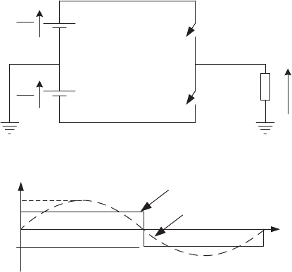
III.6.1 Single-phase voltage source inverter
A simple single-phase inverter is shown in Figure III.19. In this arrangement two
voltage-controlled switches are used. For clarity they are shown as S
1
and S
2
.These
two switches are turned ON and OFF in a complementary manner so as to obtain a
square waveform at the output of the inverter. When S
1
is ON and S
2
is OFF, the
voltage across the load is V
DC
=2. On the other hand when S
1
is OFF and S
2
is ON,
the voltage across the load is V
DC
=2. Even though the output of this inverter is a
square wave, from Fourier analysis it can be shown that the fundamental component
of the voltage across the load is a sinusoid at the switching frequency of the switches.
2
v
dc
2
v
dc
v
L
Electronic
switch
Load
DC source
S1
S2
−v
dc
/2
+v
dc
/2
Fundamental
sinusoidal component
S1-ON
S2-OFF
S1-ON
S2-OFF
Square wave
V
F
v
L
Figure III.19 A square wave inverter
1. Harmonics
From Fourier analysis, it can be shown that a square wave signal is formed by the
addition of infinite number of sinusoids. The Fourier series of the square wave is
238 Distributed generation

given by:
v
L
¼
4V
DC
p
X
1
n ¼1;3;5
sin nwt
n
¼ V
F
sin wt þ
V
F
3
sin 3wt þ
V
F
5
sin 5wt þ
V
F
7
sin 7wt þ
V
F
9
sin 9wt:::
ðIII:1Þ
where V
F
¼ 4V
DC
=p is the peak value of the fundamental (shown in dotted in
Figure III.19).
As the output contains significant higher order frequency components (har-
monics), this inverter has limited applications (and is mainly used for low-cost off-
grid systems). The harmonic voltages increase the losses in the loads connected to
the inverter and create pulsating torques in any connected motors and generators.
The utilities also impose restrictions on the harmonics that can be generated by
power electronic equipment to minimise the nuisance caused by harmonics to the
other consumers connected in the utility grid.
In order to minimise the harmonic generated by the converter, that is to syn-
thesise an approximation to a sine wave from a DC voltage source, various mod-
ulation strategies are used and they include the following.
● Carrier modulated techniques that compare a reference signal with a trigger
signal. The most well known of these is sinusoidal pulse width modulation
(PWM) which is easily implemented in hardware.
● Hysteresis control.
● Programmed pulse width modulation (sometimes known as selective harmonic
elimination, SHEM).
● Space vector modulation.
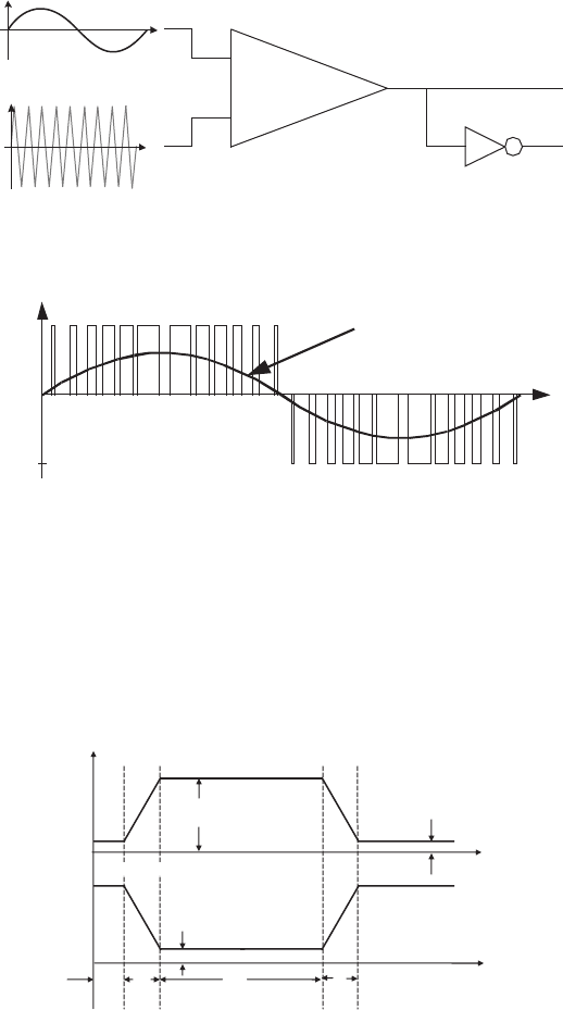
In the case of pulse width modulation (PWM) tech nique two switches, S
1
and
S
2
, are turned ON and OFF as shown in Figure III.20. A modulation signal at the
same frequency as the fundamental required at the inverter output is compared with
a high frequency triangular carrier signal. Typically, a carrier of 2–30 kHz is used.
When the triangular signal is greater than the modulation signal switch S
1
is turned
ON and switch S
2
is turned OFF in a complementary manner. The resultant output
voltage waveform of this inverter is shown in the bottom trace of Figure III.20.
In hysteresis control the output is controlled to within reference bands on either
side of the desired wave. In programmed pulse width modulation sophisticated
optimisation strategies are used, off-line, to determine the required switching
angles to eliminate particular harmonics. In space vector modulation the output
voltage space vector of the converter is defined and synthesised. This is convenient
to implement using a digital controller through a two-axis transformation.
Even though the output voltage has a number of pulses, from Fourier analysis
it can be shown that the output of the PWM inverter has reduced lower order
harmonics to less than that of a square wave inverter.
Power electronics 239
2. Losses
Each pulse of the PWM waveform has two transients, turn ON transient and turn
OFF transient, shown in Figure III.21 (for clarity the transient times are exaggerated
in the figure).
t
ON
t
C
t
OFF
V
ON
I
ON
I
OFF
V
S
Current (A)
Voltage (V)
Figure III.21 Typical turn ON and turn OFF transients of switching devices
The total power dissipation is the sum of the switching transition losses (turn
ON and turn OFF) and the ON state conduction loss. For the switching transitions
Comparator
⫹
⫺
Inverter
to S2
to S1
Carrier triangular
waveform (2kHz)
Modulation signal
(50Hz)
−v
DC
/2
+v
DC
/2
Fundamental
sinusoidal component
Figure III.20 Pulse width modulation technique
240 Distributed generation
shown in Figure III.21, the total loss is approximately given by (III.2) [3]:
Total losses ¼
V
S
I
ON
t
ON
6
þ
V
S
I
ON
t
OFF
6
þ V
ON
I
ON
t
C
f
s
ðIII:2Þ
where f
s
is the switching frequency (frequency of the carrier signal) of the PWM
signal.
From (III.2), it is clear that the total loss increases with the switching
frequency.
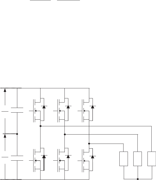
III.6.2 Three-phase voltage source inverter
In many applications three-phase inverters are utilised. The operation of a three-phase
inverter is similar to the operation of three single-phase inverters, each producing an
output phase shifted by 120
to the other. Figure III.22 shows a three-phase inverter
having six MOSFETs. The MOSFET pairs S
a1
and S
a2
,S
b1
and S
b2
, and S
c1
and S
c2
are
controlled in complementary manner.
b
a
c
s
a1
s
a2
s
b1
s
b2
s
c1
s
c2
n
o
Mid-point
(neutral)
2
V
DC
2
V
DC
Figure III.22 MOSFET-based three-phase inverter
III.7 Problems
1. Discuss the difference between the insulator, conductor and semiconductor
using energy bands.
(Answer: See Section III.2)
2. A 230 V AC mains is connected to a full-bridge diode rectifier through a 5:1
step down transformer. The ON-state drop across each diode is 0.6 V. What is
the peak value of the output of the bridge when it is not connected to a load?
(Answer: 230/5 (2 0.6) = 45.8 V)
Power electronics 241
3. A thyristor phase-controlled circuit is used to control the curren t through a
load of 10 W resistance and 4 W reactance. If the thyristor firing angle is 30
,
draw the waveform of the current.
(Answer: a ¼ 30
> tan
1
ð4=10Þ – see Example III.5.3 (3) for the plot)
4. A three-phase square wave inverter is connected to a DC source of 100 V.
Calculate the magnitude of three lowest order harmonics produced by the
inverter.
(Answer: Using (III.1): 5th = 25.5 V, 7th = 18.2 V and 11th = 11.6 V)
5. The collector of an IGBT is connected to a 300 V supply through a 10 W
resistor. The IGBT is turned ON and OFF at 10 kHz. Turn ON and turn OFF
times of the IGBT are 50 ns and 400 ns respectively. The turn ON voltage drop
can be neglected. Calculate the total losses associated with the IGBT.
(Answer: Using (III.2): Total losses = 6.75 W)
III.8 Further reading
1. Milliman J., Halkias C.C. Integrated Electronics: Analog and Digital Circuits
and Systems. Mc Graw-Hill; 1972, ISBN 0-070-423156.
2. Markvart T. Solar Electricity. Wiley; 1994, ISBN 0-471-941611.
3. Williams B.W. Power Electronics: Devices, Drives, Applications and Passive
Components. MacMillan Press; 1992, ISBN 0-333-57351X.
4. Mohan N., Undeland T.M., Robbins W.P. Power Electronics – Converters,
Applications and Design. 2nd edn. New York: John Wiley & Sons, Inc.;
1995, ISBN 0-471-58408-8.
242 Distributed generation

Tutorial IV
Power systems
Lindsey Oil Refinery Co-generation Plant
The plant produces 118 MW heat and 38 MW of electrical energy [National
Power PLC]

IV.1 Introduction
The power system converts mechanical energy into electrical energy using gen-
erators, then transmits the electricity over long distances and finally distributes it to
domestic, industrial and commercial loads. Generation is at a low voltage (400 V to
around 25 kV) and then the voltage is stepped up to transmission voltage levels
(e.g. 765 kV, 400 kV, 275 kV) and finally stepped down to distribution voltages
(e.g. 13.8 kV, 11 kV or 400 V). Each of these conversion stages takes place at a
substation with a number of different pieces of equipment to: (a) transform the
system vol tage (power transformers), (b) break the current during faults (circuit
breakers), (c) isolate a section for maintenance (isolators) after breaking the cur-
rent, (d) protect the circuit against lightning overvoltages (surge arresters) and
(e) take voltage and current measurements (voltage transformers – VT and current
transformers – CT). In addition to this primary plant, which carries the main cur-
rent, secondary electronic equipment is used to monitor and control the power
system as well as to detect faults (short-circuits) and control the circuit breakers.
Practical AC power systems use three phases that are of the same magnitude
and displaced 120
degrees electrical from each other as discussed in Tutorial I.
When the three phases are thus balanced, no current flows in the neutral and so at
higher voltages only three phase conductors are used and the neutral wire is
omitted. In order to represent the power system in control diagrams and reports, a
single line representation is used; the three-phase lines are shown by a single line.
Typical single line diagram symbols used for a balanced power system are given in
Table IV.1 and a single line diagram is shown in Figure IV.1.
IV.2 Power transformers
The power transformer is a key component of the power system, Figure IV.1,
increasing the voltage from the generators and then reducing it for the loads.
One coil is connected to a voltage source (directly or through other power
system components) and called the primary winding (N
1
) and the other coil is
connected to a load and called the secondary winding (N
2
). A mutual magnetic flux
produced by the alternating current in the primary winding links with the secondary
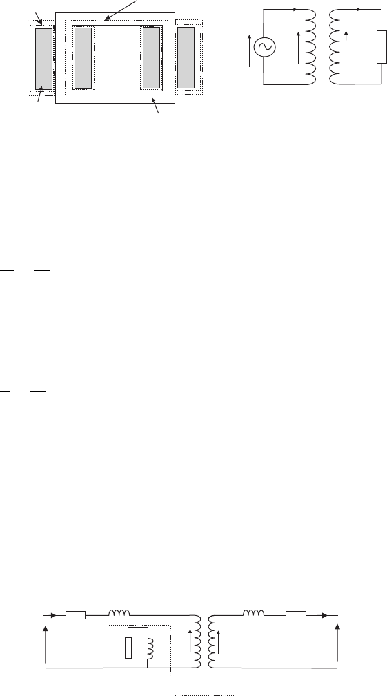
winding and induces a voltage in it. The equivalent circuit of an ideal transformer,
where flux produced by the primary links completely with the secondary, is shown
in Figure IV.2(b).
If flux in the core is f = f
m
sin wt, then from Faraday’s law:
E
1
¼ N
1
df
dt
¼ wN
1
f
m
cos wt ðIV:1Þ
where E
1
is the internal voltage of the primary.
Assuming that f links completely with the sec ondary of the transformer, the
secondary internal voltage:
E
2
¼ N
2
df
dt
¼ wN
2
f
m
cos wt ðIV:2Þ
244 Distributed generation
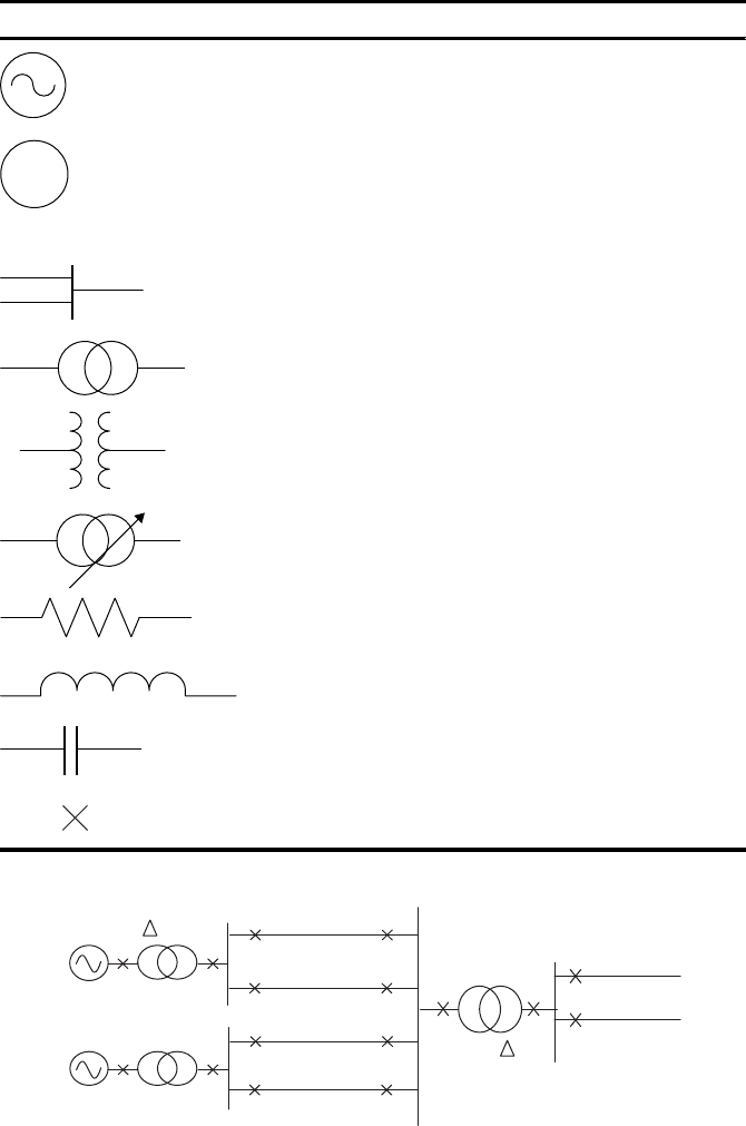
Table IV.1 Typical symbols used for one line diagrams
Symbol Description
Generator
M
Motor
_______________ Transmission line or cable
Busbar
Transformer (two winding)
Upper symbol – commonly used in the Europe
Lower symbol – commonly used in the United States
Transformer with tap changer
Resistor
Reactor
Capacitor
Circuit breaker
13/132 kV
13/132 kV
Gen 2
Gen 1
132 kV
132/33 kV
33 kV
Y
Y
Figure IV.1 One line diagram of part of the power system
Power systems 245
Dividing (IV.1) by (IV.2), the following relationship is obtained for the ratio of
the magnitudes of E
1
and E
2
:
E
1
E
2
¼
N
1
N
2
ðIV:3Þ
Equating the volt-ampere rating of the primary and secondary:
E
1
I
1
¼ E
2
I
2
¼
N
2
N
1
E
1
I
2
I
1
I
2
¼
N
2
N
1
ðIV:4Þ
In a real transformer, a small amount of flux links only with the primary and
that component of the flux is called the leakage flux. A similar leakage flux exists
on the secondary side.
For analysis of a transformer, it is convenient to use an equivalent circuit.
Figure IV.3 shows the equivalent circuit of the transformer where R
1
and R
2
rep-
resent the resistances of the primary and secondary windings, X
1
and X
2
represent
the reactances of the windings due to leakage fluxes, X
m
represents the reactance of
the mutual flux, R
c
represents the core losses, and E
1
and E
2
are the internal voltage
on each coil.
E
2
N
2
:N
2
X
2
R
2
X
1
R
1
X
m
R
c
E
1
V
1
V
2
I
1
I
2
Ideal
transformer
Magnetising
branch
Figure IV.3 A basic structure of a transformer [1]
(
a
)
Basic structure
(
b
)
Equivalent circuit
V
1
E
1
E
2
I
1
I
2
N
1
:N
2
Magnetic
core
Coil
N
1
N
2
Leakage
flux
Mutual flux
Figure IV.2 A single-phase transformer
246 Distributed generation