Jan Svoboda. Magnetic Techniques for the Treatment of Materials
Подождите немного. Документ загружается.

450 CHAPTER 5. PRACTICAL ASPECTS OF MAGNETIC METHODS
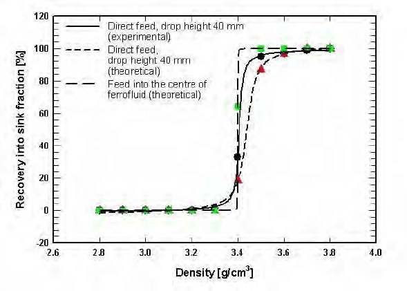
Figure 5.117: The experimental and theoretical partition curves for two modes
of feeding: directly onto the top of the fluid and directly into the
centre of the fluid [M14].
and US Bureau of Mines FHS machines [F8]. Particle flow modelling of such
a feeding mode has shown that in addition to the control of the initial velocity
of particles entering the fluid, interactions among particles can be reduced to a
minimum [M14]. In this mode, float and sink particles move in opposite direc-
tions, their interactions, leading to misplacement, are reduced and selectivity of
separation is improved, as illustrated in Fig. 5.117.
The selectivity of FHS
As has been discussed in Section 4.8.2, conditions of constant field gradient
along the vertical axis and zero gradient in transverse directions, as expressed
by eqs. (4.61), can be met only in the plane of symmetry passing through the
centre of the interpolar gap. In a real situation the field gradient along the
horizontal axis ({-axis, as denoted in Fig. 4.55) is always dierent from zero.
The horizontal component of the magnetic field increases from the centre of the
gap towards the pole tips and as a result of the field gradient thus created the
surface of the ferrofluid forms a meniscus. The particles are pushed towards the
centre of the gap, where the gradient and thus the apparent density, are lower.
While, in principle, this phenomenon improves the accuracy of separation, it
increases the crowding of the particles and the rate of interparticle interactions,
it reduces the eective volume of the separation chamber in which separation
takes place.
5.6. SEPARATION IN MAGNETIC FLUIDS 451
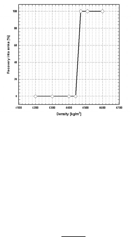
Figure 5.118: The experimental partition curve of Rhomag
R
°
ferrohydrostatic
separator (De Beers) with hyperbolic pole tips, determined with
2 mm density tracers. Cut point density: 4450 kg/m
3
[S8].
It is evident, therefore, from the foregoing discussion that the upper limit
of selectivity of separation can be achieved only when particles are fed into the
centre of the interpolar gap at a very low feed rate. Figure 5.118 illustrates the
partition curve of an FHS separator equipped with hyperbolic pole tips. The
curve was obtained using 2 mm density tracers and kerosene-based ferrofluid.
It can be seen that the separator could "see" a density dierence as small as 30
kg/m
3
(0.03 g/cm
3
), which corresponds to the probable error of separation Hs,
defined by eq. (5.32), as low as 0.007.
Hs =
75
25
2
(5.32)
where
75
and
25
are the densities of particles, 75% and 25% of which report
into the sink fraction.
The eect of fluid level
From the analysis of particle trajectories in a ferrofluid outlined in Section 3.8,
the accuracy of separation depends on the depth of the fluid. The degree of
influence of the fluid depth depends on the mode of feeding, drop height, design
and length of the separation chamber, position of the splitter, particle size, and
density dierential between the materials to be separated. Typical dependence
of the e!ciency of separation on the depth of the ferrofluid pool is shown in
Fig. 5.119. It can be seen that the accuracy of separation of tracers of density
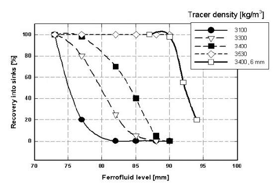
452 CHAPTER 5. PRACTICAL ASPECTS OF MAGNETIC METHODS
Figure 5.119: The e!ciency of separation of 2 mm density tracers in a ferrofluid
with cut-point density of 3450 kg/m
3
, as a function of the fluid
level. Comparison with 6 mm tracers of density 3400 kg/m
3
is also
shown [D16, S8].
higher than the cut-point density is not aected by the fluid level. However,
misplacement of the floating tracers increases with decreasing fluid level and
this misplacement becomes more pronounced for near-density tracers.
Such a behaviour of particles in the ferrofluid can be explained by realizing
that the gradient of the magnetic field, and thus the apparent density of the
ferrofluid are constant only in a limited region along the vertical as shown in Fig.
4.57. In a region closer to the bottom section of the pole tips the field gradient
rapidly decreases and so does the apparent density. Float particles that happen
to reach this low-density region, as a consequence of their parabolic trajectories,
will report into the sink fraction. This misplacement becomes more pronounced
with increasing size of the particles, as shown in Fig. 5.119.
The eect of particle size
It is a well-confirmed fact that particle size plays an important role in any
type separation, and ferrohydrostatic separation is no exception. As has been
discussed in Section 3.8.5, the motion of particles in a ferrofluid is determined by
the interplay of assorted forces acting on the particles, and the balance of these
forces determines the trajectory of a particle in the ferrofluid and ultimately
the fraction into which the particle will report. The force of gravity, and the
magnetically and gravitationally-derived buoyancy forces, depend on the cube
of the particle size, while the hydrodynamic drag depends only on the first power
5.6. SEPARATION IN MAGNETIC FLUIDS 453
of the diameter. It is clear, therefore, that the separation e!ciency will depend,
to some extent, on particle size.
It has been shown in Section 3.8.3, that for particles smaller than 1 mm,
the eective cut-point density is dependent on particle size, and the selectivity
of separation is, therefore, impaired. For particles smaller than 0.1 mm the
eect of hydrodynamic drag becomes so pronounced that accurate separation
of materials with a narrow density dierence is virtually impossible.
For particles greater than 1 mm, the influence of hydrodynamic drag is negli-
gible and separation should be fairly accurate. The performance of a separator,
however, becomes aected by design parameters, such as depth of the fluid,
length of the separation chamber, position of the splitter and mode of feed-
ing. As in any separation technique, classification into reasonably narrow size
fractions improves the e!ciency of separation.
The upper limit of particle size that can be treated by FHS is determined
by the width of the bottom part of the tapered separation chamber which, in
turn, is determined by the width of the air gap of the magnet. Ferrohydrostatic
separators designed to treat particles up to 100 mm in diameter have been built
[G4].
The eect of feed rate
The processing capability of a ferrohydrostatic separator is of considerable eco-
nomic importance. The feed rate aects the separation e!ciency and the op-
timum value of the feed rate is in turn a function of particle size and shape,
density dierence between the materials to be separated, mass split between
the sink and float fractions, design of the separation chamber and of the feeding
system, and on metallurgical requirements.
In general, as the feed rate through the separator increases, the separation
e!ciency decreases. Interparticle collisions, particularly among the sinking and
floating particles, result in the change of their trajectories and thus in their mis-
placement. In addition, an increase in the feed rate shortens the residence time
of particles in the fluid pool and leads to further misplacement of the particles.
These eects are more pronounced for feeds with a narrow size distribution, for
particles with a small density, dierence and for particles with densities close to
the apparent density of the ferrofluid.
The maximum feed rate acceptable from a metallurgical point of view is thus
determined by so many variables that no general rule can formulated and only
experimental tests can give information on the optimum operation of a ferro-
hydrostatic separator. Experience with separation of a wide range of materials
in a separation chamber, shown in Fig. 5.110, with direct feed onto the top of
the fluid, indicates that the approximate maximum feed rate is frequently of the
order of 400 kg/h per 100 mm of width of the feeder tray [S8].
A similar feed rate was used in the Hitachi FHS [N4] for an easy separation
of aluminium ( = 2700 kg/m
3
) from zinc ( = 7140 kg/m
3
) and copper ( =
8960 kg/m
3
) from metal scrap, in the particle size range - 50 + 6 mm.
The Tohoku University and Nittetsu Mining Co. (Japan) ferrohydrostatic
454 CHAPTER 5. PRACTICAL ASPECTS OF MAGNETIC METHODS
separator for metal scrap recovery was operated at a feed rate of 700 kg/h/100
mm [S50, F8], while a feed rate as high as 1000 kg/h per 100 mm width of the
feeder tray was employed in the US Bureau of Mines FHS [K17], in a similar
application. The width of the feeder trays and of the separation chambers
ranged from 100 to 200 mm in these applications, corresponding to throughputs
between 500 kg/h and 2t/h.
Density stability and its control
For the accurate and selective separation of materials with small density dif-
ferences it is necessary to maintain accurate control over the apparent density.
Over a period of operation of FHS, the apparent density and the level of fer-
rofluid changes, as a result of temperature variations, ferrofluid evaporation and
changes in the operational characteristics of an electromagnet. One approach
to achieving high stability of the apparent density is to use a PC-based control
system that allows an operator to select the desired cut-point density from a
computer screen and the system then automatically controls the separator at
the set point. The apparent density can be continuously monitored, for exam-
ple, with the aid of a strain gauge. Any change in the apparent density, sensed
by the strain gauge, is used as an input into the closed loop control system that
manages the power supply operation so that a constant apparent density of the
ferrofluid is maintained.
Such an automated control of the system requires the separator to be accu-
rately calibrated. The calibration procedure is carried out using density tracers.
Once the system is calibrated and the apparent density has been determined,
the closed loop system automatically adjusts the apparent density to suit the
required cut point density.
5.6.3 Ferrofluid recovery and recycling
In order to keep the running costs of ferrohydrostatic separators low, it is es-
sential, for most applications, that the ferrofluid be recovered and recycled. At
the same time, from the environmental point of view, it is imperative to remove
tracers of ferrofluid from the products of separation. Several methods, usually
e!cient and cost-eective, have been developed for the recovery and recycling
of water-based and kerosene-based ferrofluids.
Recovery of a water-based ferrofluid
A water-based ferrofluid adhering to the products of separation can be easily
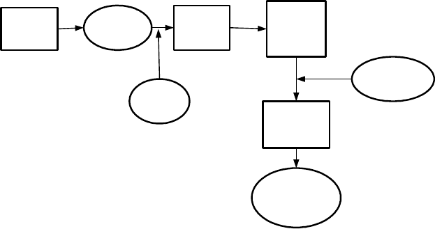
removed by washing the material with water. Fujita et al. [S50, F8] developed
a process for ferrofluid recovery outlined in Fig. 5.120. After the products of
separation are washed with water, the diluted suspension is acidified to change
the surfactant (sodiumdodecyl-benzene sulphonate), providing the secondary
adsorption layer, to free acid. A thickener and a centrifugal separator can then
be used to separate flocs from the excess water due to the washing process. The
5.6. SEPARATION IN MAGNETIC FLUIDS 455
Washing
Diluted
ferrofluid
Coagula-
tion
Ferrofluid
recovery
Dispersion
Acid
Alkali
surfactant
Concentrated
ferrofluid
Figure 5.120: Recovery of water-based ferrofluid (adapted from Fujita [F8]).
concentrated flocs thus obtained are re-dispersed as a concentrated ferrofluid
by adding alkali and the lost surfactant. The loss of ferrofluid in this process is
claimed to be about 0.1% of the feed by weight. Diluted water-based ferrofluid
can be re-concentrated also by ultrafiltration, a slow and potentially onerous
process.
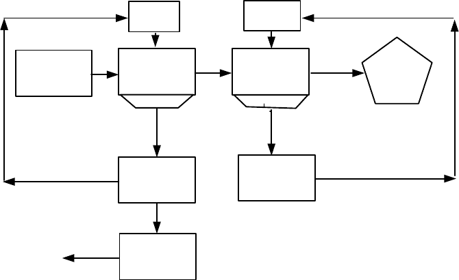
Recovery of a kerosene-based ferrofluid
A well-established procedure for recovering kerosene-based ferrofluid from the
products of separation is to wash particles with water. As this ferrofluid is
immiscible with water, the resulting emulsion can be separated either by set-
tling [R9, F27] or in a magnetic field [G17, D16, S81]. The latter approach is
very e!cient and quick, and numerous designs of the magnetic-field-based fer-
rofluid recovery systems have been proposed [G19, G20, G21, S81]. A schematic
diagram of such a recovery system is shown in Fig. 5.121.
After the water wash, the emulsion is passed over a permanent magnet circuit
where the concentrated ferrofluid is separated from the wash water. A chamber
situated between the magnet pole pieces allows water to be displaced to the
top of the chamber, while the ferrofluid is attracted to the bottom part where
the magnetic field is strongest. The rate of drainage of the ferrofluid from the
chamber is determined by the ratio between the weight of the ferrofluid and
the holding strength of the magnetic system. The e!ciency of recovery of the
ferrofluid by this method is, for particles bigger than 0.5 mm, usually greater
than 99%, even for rather porous materials,
In those applications where the final product(s) of separation have to be very
456 CHAPTER 5. PRACTICAL ASPECTS OF MAGNETIC METHODS
Water wash
Detergent
wash
Magnetic
circuit
Recovered
ferrofluid
Water
sprays
Detergent
sprays
Detergent
Clean FHS
product
FHS products
Ferrofluid/water
mixture
Water
To FHS
Figure 5.121: Schematic diagram for recovery of kerosene-based ferrofluid.
clean, for instance for visual inspection, or where the value of the final product
is to be enhanced, the traces of hydrocarbon and magnetite must be removed
from the surface of the grains. This can be accomplished, for instance, by using
a biodegradable detergent [K23]. The inclusion of the detergent washing stage
in the ferrofluid recycle circuit is shown in Fig. 5.121. This additional step is
also essential for the cleaning of small particles, as the water wash alone is not
su!ciently e!cient for particles smaller that 0.5 mm [F27].
Although the kerosene-wash is more e!cient than the water wash, partic-
ularly for small particles [F27], its e!ciency is still unsatisfactory, mainly for
porous materials. It has been observed that, for instance, petrol can recover
more ferrofluid, by at least a factor of two, compared to kerosene [S8]. Straight-
chain aliphatics including petrol, are much less sterically hindered and have
enhanced solvating power. This results in better dissolution of the ferrofluids
from the pores and crevices for petrol compared with kerosene.
It is well-established experimentally, that the temperature of water does
not aect the e!ciency of ferrofluid recovery in the temperature range from
20
0
Cto60
0
C [S8, K25, F27]. Similarly, a high water flow rate was not
found to be advantageous in removing ferrofluid from particles [F27]. However,
pre-treatment of grains, for example by pre-wetting with water or other fluids,
resulted in more e!cient removal of ferrofluid from the material and thus in
reduced losses of the fluid [G17].
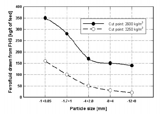
5.6. SEPARATION IN MAGNETIC FLUIDS 457
Figure 5.122: Kerosene-based ferrofluid drawn from FHS at dierent apparent
densities (adapted from [D16]).
Losses of ferrofluid
Although the methods of ferrofluid recovery, which have been discussed, are
very e!cient, some ferrofluid is always lost during the separation and recovery
processes. This loss, and the e!ciency of the ferrofluid recovery, depend mainly
on particle size, moisture content, surface preparation and porosity of particles.
Figure 5.122 shows that the amount of ferrofluid drawn by the products of
separation from the FHS separator depends mainly on the particles size and on
the operating apparent density of the ferrofluid. It can be seen that the amount
of ferrofluid drawn decreases with increasing apparent density, for a ferrofluid of
constant magnetization. At a higher apparent density, and thus higher magnetic
field, more fluid is held back by the magnetic field as the products of separation
emerge from the separator.
Typical losses of ferrofluid for various sizes of kimberlite are summarized in
Table 5.37. These values agree well with those reported by Gubarevich [G17]
for various non-ferrous ores and coal, at a size range, as a rule, of - 25 + 1 mm.
For materials with low porosity, such as metals, the losses are much lower.
Solodenko and Karmazin [S71] investigated the eect of pre-treatment of the
feed material on losses of ferrofluid. They observed that by wetting the material
with water, losses of kerosene-based ferrofluid can be reduced by a factor 4 to 7.
In addition, a novel method of material pre-wetting was proposed, and it was
found that ferrofluid losses as low as 0.005 to 0.01 kg per tonne of the feed can
be achieved.

458 CHAPTER 5. PRACTICAL ASPECTS OF MAGNETIC METHODS
Table 5.37: Loss of kerosene-based ferrofluid after water-wash of kimberlite
[D16, F20, S8, S82]).
Size fraction [mm] Loss of ferrofluid [kg/t of feed]
-1 + 0.85 0.7
-1.7+1 0.58
-4+2.8 0.28
-8+4 0.27
-12+8 0.12
5.6.4 Separation in a rotating ferrofluid
Magstream
It has been discussed in Sections 2.8.3 and 3.8.6 that a serious limitation of
ferrohydrostatic separation is the ine!cient separation of fine particles. A pro-
posal to replace the force of gravity by a centrifugal force as the competing force
to the magnetically derived buoyancy force resulted in the development of the
rotation-based Magstream process [W7].
Numerous experimental investigations into the operational characteristics of
Magstream showed that the selectivity of this separator is 100 kg/m
3
or worse
[K26]. In the application of Magstream to the separation of beach sands [K26]
the probable error Ep, defined by eq. (5.33) ranged from 0.14 to 0.43.
Hs =
90
10
2
(5.33)
Based on experimental results with materials in the size range from 1 mm to
45 m, Kojovic [K26] proposed that the e!ciency of separation Ep of Magstream
could be approximated by an expression
Hs =0=04 + 0=05
4(
fs
i
)
2
M
v
10
10
(5.34)
where
fs
is the cut-point density and
i
is the ferrofluid density, both expressed
in kg/m
3
, while the saturation polarization of the ferrofluid M
v
in given in T.
It is clear from eq. (5.34) that a greater precision of separation is achieved
for lower cut-point density and with a fluid of higher magnetic polarization. It
can also be seen that selectivity of Magstream is at least an order of magnitude
lower than that of ferrohydrostatic separation.
An important disadvantage of Magstream is that it is not possible to measure
the apparent density of the ferrofluid and thus to calibrate the instrument. The
apparent density and thus the cut-point density can be only calculated from eq.
(3.173) and their determination is thus as accurate as the theory from which
such an equation was derived.
A significant problem that aected the accuracy of Magstream was the low
magnetization and high viscosity of the biodegradable water-based Magstream
5.7. MAGNETISM IN OTHER AREAS OF MATERIAL HANDLING 459
ferrofluid. A rather steep dependence of the fluid magnetization on its density
resulted in a high sensitivity of the fluid density and thus of the cut-point density
to the ambient temperature and to the temperature of the ferrofluid within the
separation space.
In view of the fact that the Magstream concept is potentially advantageous
compared to static techniques such as ferrohydrostatic separation, exploitation
and further development of this concept would be worthwhile and it could result
in a really accurate separation technique.
Separation in a hydrocyclone using magnetic fluids
Another innovative concept how to eliminate the poor separation e!ciency of
fine particles in ferrohydrostatic separators was proposed by Lin and Fujita
[L18, L19]. A cyclone was placed between the pole tips of a magnet that gen-
erated a non-homogeneous magnetic field. The apparent density of a ferrofluid
introduced into the cyclone could be controlled by pressure dierential and flow
rate. This concept combined the principles of centrifugal and ferrohydrostatic
levitation. Selective separation of material as fine as 38 mintotheoverflow
and underflow fractions was achieved in a continuously variable density range
up to 5000 kg/m
3
.
5.7 The application of magnetism in other areas
of material handling
The e!ciency of separation of a mixture of materials into individual components
which have properties of similar magnitude (for instance density, magnetic sus-
ceptibility, electrical and thermal conductivity, and others) can be increased
by simultaneous exploitation of two or three of these properties. By providing
such additional external forces, which can vary over a wide range of values, it
is possible, in principle, to manipulate a material more e!ciently under a wide
spectrum of experimental conditions.
Magnetic forces oer a unique approach to material manipulation. One
of the main advantages of material treatment in a magnetic field is that the
magnetic force can be superimposed on other physical forces and several physical
properties of materials can, therefore, be exploited simultaneously. There are
numerous examples where innovative combinations of forces, including magnetic
force, were attempted, albeit with varying degree of success. The most natural
approach to synergetic application of multiple forces in material handling is a
combination of a magnetic force with the force of gravity. Magnetic force has
been applied to spirals, tables, jigs and hydrocyclones. Attempts have also been
made to apply magnetism to vacuum filtration and column flotation. A brief
review of these attempts is given below.