Jan Svoboda. Magnetic Techniques for the Treatment of Materials
Подождите немного. Документ загружается.


280 CHAPTER 4. DESIGN OF MAGNETIC SEPARATORS
4.4.1 The power requirements
The magnetic induction generated directly by the coil itself can be calculated
using eqs. (4.46) and (4.48). The power Z (in watts), required to generate a
given magnetic induction, is then given by:
Z =
(d
2
1
2e(d
2
d
1
)
2
(
2
1)(QL)
2
(4.51)
where ( is resistivity of the conductor and is the filling factor of the winding
defined as
=
active section of the winding
total section of the winding
(4.52)
Combining eqs. (4.41) and (4.51) it can be seen that the power is proportional
to the square of the number of ampere-turns and thus of magnetic induction,
Z E
2
j
.
While the electric current L and the number of turns Q are related by eq.
(4.41), the necessary voltage can be found from Y = LU> where the resistance
of the winding can be calculated from:
U =
2(Q
D
G
phdq
=
(( +1)
2( 1)d
1
Q
2
(4.53)
where D is the cross-section of the winding and G
phdq
is the mean diameter of
the winding.
4.4.2 The choice of the conductor
The choice of the conductor, between copper and aluminium, determines the
maximum current density, the mass and the volume of the coil and the cost of
the magnet. Copper is 3.3 times denser than aluminium (8960 kg/m
3
vs 2699
kg/m
3
) and for equal coil sizes aluminium will make a much lighter coil. On the
other hand, resistivity of aluminium is about 1.58 times greater than resistivity
of copper (2.45×10
8
m vs 1.555×10
8
mat0
0
C), 1.58 time more power is
required by the aluminium coil to generate the same field. Detailed analysis of
the relative merits of aluminium and copper coils, as a function of coil geometry,
mass and cost can be found in [M22].
4.4.3 The cooling of coils
The removal of the Joule heat generated inside the winding can be accomplished
in several ways. Indirect air cooling can be applied to magnets operating at low
current densities, generally not exceeding 3 A/mm
2
for a copper conductor.
Direct immersion of the coil into the circulating oil or water greatly improves
heat conduction and transfer and higher current densities can be used.
The operating current density can be increased considerably by using hollow
conductors through which the cooling liquid circulates. Water is a very e!cient

4.4. DESIGN OF SOLENOID MAGNETS 281
coolant in removing heat at conventional temperatures. The oils, for example,
have heat-transfer characteristics about one-fifth that of water [D11]. Coils
with low resistance, operating at low voltage, are almost always cooled with
deionized or demineralized water, mains water causing electrolysis even at low
voltage. The cooling water is circulated through the coil, a heat-exchanger, a
filter and a deionizer. In the heat-exchanger the heat is carried o by tap water.
The flowrate of water T (in cm
3
/s or m
3
/h) required to restrict the temper-
aturerisetoW (in
0
C) in a magnet with power input of Z (in watts) is given
[M22] by:
T =
Z
4=186W
(fjv)=
Z
1163=7W
(VL) (4.54)
For instance, for a 250 kW magnet, with temperature rise of W =30
0
C, the
required flowrate is approximately 2000 cm
3
/s, or 7.2 m
3
/h.
The operating temperature of a magnet aects the resistance of the winding
and thus the power needed to achieve the required magnetic field. The hotter
the coil, the higher the resistance will be and the more power will be needed.
The temperature dependence of resistivity of conductors can be written
(
W
= (
20
[1 + (W 20
0
F)] (4.55)
where (
W
and (
20
are resistivities at temperature W and 20
0
C, respectively
and is the temperature coe!cient. For copper (
20
=1.72×10
8
mand
= 0.0041/
0
C, while for aluminium (
20
= 2.7×10
8
mand = 0.0045/
0
C.
Therefore, a copper conductor operating at 60
0
C has resistivity of 2×10
8
m,
while an aluminium conductor has resistivity of 3.2×10
8
m.
Whether or not the amount and flow velocity of the coolant, as determined
by eq. (4.54), can be forced through the winding of the magnet depends on the
pumping power available and on the detailed structure of magnet. The pressure
drop across a tube is the sum of the entrance and exit losses and frictional drop
in the tube. The total pressure drop S (in Pa) becomes
S =(0=74 + 0=015
O
g
)10
3
y
2
(4.56)
where O and g are the length and diameter of the cooling path (in m), and
y is the coolant velocity (in m/s). A typical pressure drop for copper hollow
conductors is 0.5 to 0.8 MPa.
4.4.4 Thickness of the iron cladding
The basic requirement for the iron cladding is that it must not be saturated.
The magnetic flux in the cladding is M
v
D
f
where D
f
is the cross-sectional area
of the cladding. In order to avoid oversaturation of the cladding, the following
inequality must be satisfied:
E
j
D
j
5 M
v
D
f
(4.57)
where E
j
is the magnetic induction in the air gap of cross-sectional area of D
j
.
The thickness of the cladding can thus be found from this equation.

282 CHAPTER 4. DESIGN OF MAGNETIC SEPARATORS
Table 4.5: Properties of decarburized steel for high-field magnets [B1].
Chemical composition 0.05 - 0.02% C, 0.2% Mn, 0.02% S
0.05% Cu, 0.01% P, 0.02% Ni
Coercivity H
max
f
60 to 80 Am
1
Permeability B A 0.04 T at H = 40 Am
1
B A 1.5 T at H = 1200 Am
1
B A 2.0 T at H = 2400 Am
1
ThechoiceofthevalueofM
v
is important for correct dimensions of the iron
cladding. The values of saturation polarization for commercial steels are usually
not available and the value of 1.5 T or less should be used. Low-carbon decar-
burized steel is frequently used in high-field magnets and typical specifications
are shown in Table 4.5 [B1].
Several important rules relating to the usage of iron cladding can be outlined:
• Magnets for which the length of the air gap is greater than the inner
diameter of the solenoid, i.e. O
j
A 2d
1
, do not require the iron pole above
and below the working volume. On the other hand, when O
j
? 2d
1
,the
presence of iron cladding in the vicinity of the working space is necessary.
• By replacing the external air path with a magnetic circuit of low reluc-
tance, the most significant increase in the magnetic induction, for a given
magnetomotive force, can be obtained for solenoids of small axial length.
Therefore, the contribution of the iron is largest if the coil has a consid-
erable stray magnetic field. In the case of a long thin solenoid, in which
the stray field is small, the eect of an external iron circuit is negligible.
4.5 Design of drum magnetic separators
4.5.1 The basic magnet arrangements
The basic design of the magnetic circuit of drum magnetic separators is com-
mon to most commercially available models. Permanent magnet blocks are
stacked on top of each other in a specific geometrical arrangement. The sim-
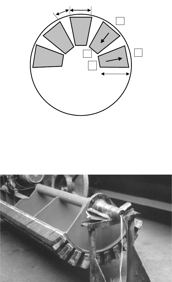
plest arrangement is shown in Fig. 4.26. Strontium or barium ferrite blocks,
usually magnetized through their thickness are frequently arranged radially in
low-intensity drums. The frequently used size of the blocks is 150 mm long,
100 mm wide and 25 mm thick. The number of blocks per stack is determined
by the diameter of the drum. These radially magnetized stacks are most often
arranged in rows parallel with the axis of the drum, separated by an air gap. A
radial arrangement is also used, as discussed in Section 2.1.5. and as shown in
Fig. 2.12. Figure 4.27 illustrates the axial arrangement of magnet blocks in a
magnetic drum.
4.5. DESIGN OF DRUM MAGNETIC SEPARATORS 283
b
a
S
N
S
N
L
Figure 4.26: Schematic diagram of radially magnetized magnets in a magnetic
drum with axial arrangement of the poles.
Figure 4.27: Axial arrangement of magnet blocks in a magnetic drum.

284 CHAPTER 4. DESIGN OF MAGNETIC SEPARATORS
N
S
S
N
N
S
Figure 4.28: Position of a backing magnet (cross pole) in a drum magnetic sep-
arator.
High-intensity drum separators employ rare-earth magnets, usually NdFeB,
and it is a common practice to simply replace ferrite magnets with rare-earth
blocks, with the intent to achieve a higher magnetic field [A13]. The rare-earth
blocks are smaller than the ferrite blocks, for example 50×50×15 mm.
Another arrangement of permanent magnets which is frequently employed
is shown in Fig. 4.28. A ferrite magnet, magnetized in a transverse direction
is inserted between the radially magnetized stacks of permanent magnets. Ex-
planations of the function of this "backing" of "blocking" magnet (or "cross
pole") are as numerous as its names. Reduction of the leakage flux between
the adjacent main stacks and addition of extra flux [M19] are the most likely
explanations of the benefit that this arrangement oers.
4.5.2 Geometry of the magnet assembly
Although drum magnetic separators are one of the oldest types of magnetic
separators, and certainly the most widely used, design of the magnetic circuit
is still to a great extent empirical. A simple rule for geometrical arrangement
of the magnet blocks that was used for many decades states that the ratio of
the magnet block width e and the width of the air gap d should be e@d = 3
to 5 for ferrite and rare-earth magnets and e@d = 1.2 for Alnico magnets and
electromagnets [D4]. The design dierence is the result of dierent demagne-
tization behaviour of the permanent magnet materials, as shown in Fig. 4.2.
Using computer modelling, this design rule has been revised, as will be discussed
later.
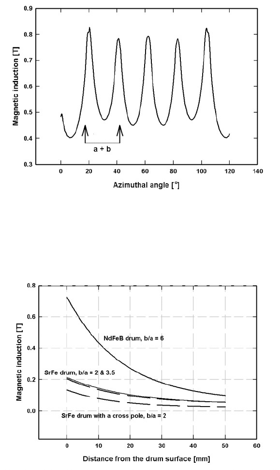
A typical distribution of the field pattern along the circumference of a drum
with axial pole arrangement is shown in Fig. 4.29. The maxima in the magnetic
induction occur at the centres of the air gaps while the minima occur at the
centre of the magnet block. Comparison of the magnetic induction generated
by dierent magnet arrangements in a drum is given in Fig. 4.30.
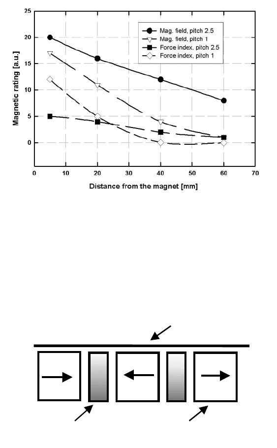
The relative values of the magnet and air gap widths aect the magnetic
field and force distribution around the drum. For instance, by reducing the
distance between the magnet blocks, or the so-called pole pitch (defined either
4.5. DESIGN OF DRUM MAGNETIC SEPARATORS 285
Figure 4.29: Distribution of the magnetic induction along the circumference of
an NdFeB drum with axially arranged poles. The width of the
radially magnetized magnets e = 100 mm and the air gap width d
= 10 mm [M24].
Figure 4.30: The maximum magnetic induction generated by dierent magnet
arrangements in an axial drum with radial magnetization of the
magnet blocks (adapted from [M10]).
286 CHAPTER 4. DESIGN OF MAGNETIC SEPARATORS
Figure 4.31: Magnetic field and force index (in arbitrary units) as a function of
distance from the drum surface, for dierent distances between the
poles (adapted from [S13]).
Ma
g
net block
Steel pole
Shell
Figure 4.32: Steel poles sandwiched between azimuthally arranged magnet
blocks.
4.5. DESIGN OF DRUM MAGNETIC SEPARATORS 287
Figure 4.33: Magnetic induction generated by magnetic drums, with three dif-
ferent magnet arrangements, as a function of distance from the
drum surface (adapted from [F19]).
Figure 4.34: Dependence of the magnetic induction on the surface of the drum,
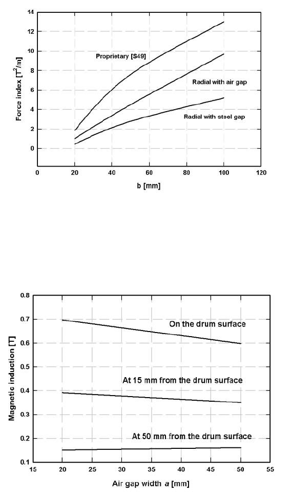
on the width e of the NdFeB magnet, for d =10mm. Three
dierent configurations are shown [M24].
288 CHAPTER 4. DESIGN OF MAGNETIC SEPARATORS
Figure 4.35: Dependence of the force index at 15 mm from the drum surface, on
the width e of the NdFeB magnet, for d =10 mm. Three dierent
configurations are shown [M24].
Figure 4.36: Magnetic induction as a function of the width d of the air gap, for
an NdFeB magnetic drum, for e = 100 mm [M24].
4.5. DESIGN OF DRUM MAGNETIC SEPARATORS 289
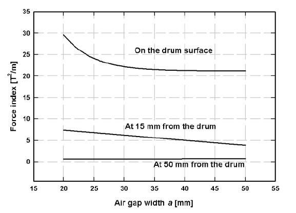
Figure 4.37: Force index for an NdFeB drum, as a function of the width d of the
air gap, for e = 100 mm [M24].
as d or d + e in Fig. 4.26), it is possible to increase the field gradient. Although
the field strength is reduced, the increase in the field gradient is su!cient to
result in the increase of the force index. The situation is depicted in Fig. 4.31.
It can be seen that the increase in the force index by reducing the pole pitch
takes place only in the proximity of the drum surface and that the force index
decreases rapidly away from the drum. In other words, the smaller the pitch,
the higher the force index on the drum surface and the shorter the reach of the
magnetic force.
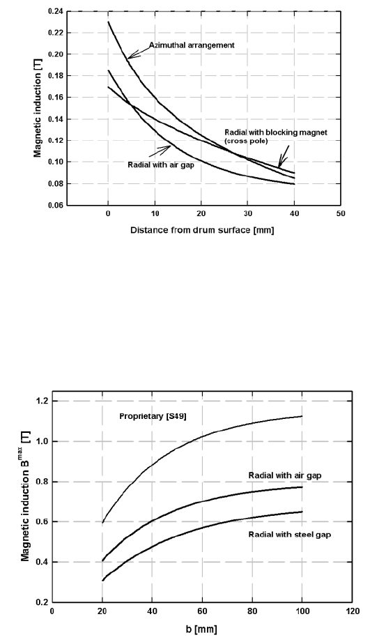
In the nineteen eighties the Fives-Lille group developed drum magnetic sep-
arators with steel poles sandwiched between ferrite magnet blocks with az-
imuthally arranged direction of magnetization, as shown in Fig. 4.32. As a
result of their superior performance, compared to the conventional design, in
terms of magnetic force and metallurgical performance, the azimuthal concept
was commercially accepted for some applications. Comparison of the magnetic
field strength achievable by the conventional and azimuthal designs is shown in
Fig. 4.33.
4.5.3 Electromagnetic modelling of the design
Electromagnetic modelling software that has become available in recent years
allows for the optimization of the design of conventional magnetic circuits. The
modelling allows the investigation of the eect of various geometrical parameters
of the drum on the magnetic field and magnetic force. For instance, Fig. 4.34
