Jan Svoboda. Magnetic Techniques for the Treatment of Materials
Подождите немного. Документ загружается.

290 CHAPTER 4. DESIGN OF MAGNETIC SEPARATORS
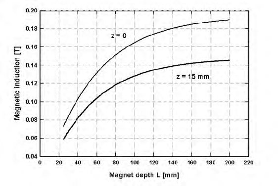
Figure 4.38: The dependence of the magnetic induction generated by a stron-
tium ferrite block 100×150 mm, on its depth O,onthesurfaceof
theblockandat15mmfromthesurface.
illustrates the variation of the magnetic induction on the surface of a drum with
the width e of the magnet block. It can be seen that for a constant width d =
10 mm of the gap, the maximum magnetic induction is achieved for the magnet
width of 100 mm. The ratio e@d = 10 is thus in disagreement with the empirical
rule-of-thumb mentioned earlier.
Figure 4.34 also shows that replacement of the air gap with a steel block
results in the reduction of the magnetic field. Similar conclusions can be drawn
from Fig. 4.35, which displays the eect of the magnet width on the force index.
The eect of the width d of the air gap on the field at various distances from
the drum surface is illustrated in Fig. 4.36. It can be seen that by increasing d,
for a constant value of the width of the magnetic block (i.e. with the ratio e@d
decreasing), the magnetic induction decreases, at least in the proximity of the
drum surface. At larger distances from the drum surface, e.g. at 50 mm, the
eect of the value of d (and thus of e@d) is diminishing. Similar trends can be
observed for the force index as shown in Fig. 4.37.
The results illustrated in Fig. 4.30 and Figs. 4.34 to 4.37 were obtained
for a drum with axial pole arrangement and with magnets magnetized radially.
The diameter of the drum was 600 mm and the depth O of the magnet stack
was 100 mm.
The eect of the depth of the magnet stack can be determined by using eq.
(4.30), which allows for the variation of the depth O , as shown in Fig. 4.9, and
for the calculation of the magnetic field generated by such a magnet block, at
dierent distances }. Figure 4.38 illustrates such a dependence for a strontium
4.6. DESIGN OF A MAGNETIC ROLL 291
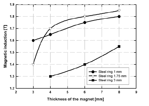
Figure 4.39: Magnetic induction on the roll surface, as a function of the magnet
ring thickness. The values of magnetic induction were obtained by
computer modelling [F18].
ferrite block, of dimensions 150 mm (Z ) × 100 mm (G). It can be seen that
the benefit of increasing the depth of the magnet stack above 140 mm is limited.
The computer modelling also allowed for the development of new geometries
of the magnet arrangement, capable of producing a higher magnetic strength
and magnetic force [A13, S8]. Some of these new designs are proprietary and the
patents are still pending. Comparison of one such a design, with conventional
designs, is shown in Figs. 4.34 and 4.35.
4.6 Design of a magnetic roll
4.6.1 Basic concepts of design
The overall view of a magnetic roll separator is shown in Figs. 2.30 and 2.31.
The magnetic roll itself forms a part of a short conveyor fed by a vibratory
feeder. The conveyor belt is made of a thin high-tensile material, often with
antistatic coating. The belt is supported by second roll (idler). Roll separators
are usually of modular design allowing them to be stacked in any number of
passes of material. Typical specifications of such a roll separator are shown in
Table 4.6.
The e!ciency of separation is aected by the roll design and by several
operating variables: the number of separation stages, belt speed, splitter posi-
tion and belt loading. Most of these variables are determined by particle size
292 CHAPTER 4. DESIGN OF MAGNETIC SEPARATORS
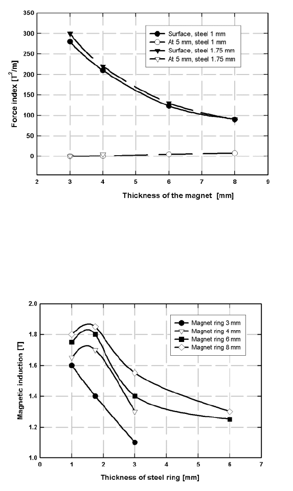
Figure 4.40: Force index as a function of the magnet ring thickness, for thickness
of steel rings equal to 1 mm and 1.75 mm, on the roll surface and
at 15 mm from the surface.
Figure 4.41: Magnetic induction on the surface of a roll, as a function of thick-
ness of steel rings, for several thicknesses of permanent magnet
rings.

4.6. DESIGN OF A MAGNETIC ROLL 293
Table 4.6: Typical specifications of a permanent roll magnetic separator.
Parameter Specification
Belt thickness minimum 0.12 mm
Roll diameter 72, 76, 100, 220 & 300 mm
Roll length 250, 500, 1000 and 1500 mm
Max. magnetic induction NdFeB: 1.9 T, SmCo: 1.5 T, SrFe: 0.5 T
distribution and magnetic properties of the feed and by the recovery vs grade
requirement.
4.6.2 Design parameters
Thicknesses of magnet and steel rings
As has been discussed in Section 2.3.3 and shown in Fig. 2.28, the roll consists
of discs or rings of permanent magnets, interleaved with mild steel rings. The
adjacent permanent magnet rings are arranged with the same polarity facing one
another, i.e. rings are arranged in a repulsive mode. The relative thicknesses
of the magnets and the steel rings aect the magnetic field strength and its
pattern around the roll. This situation is depicted in Figs. 4.39, 4.40 and 4.41.
It can be seen that the magnetic induction on the surface of a roll increases
with increasing thickness of the magnet ring. At the same time it achieves
the maximum value for a certain, rather small, thickness of the steel rings.
With further increase in the thickness of the steel rings the magnetic induction
decreases. This is a consequence of the fact that the saturation magnetization
of steel is much greater than that of the permanent magnet material. If the
thickness of the steel exceeds a certain optimum value, the magnet ring does
not succeed in saturating the steel, as transpires from eq. (4.12).
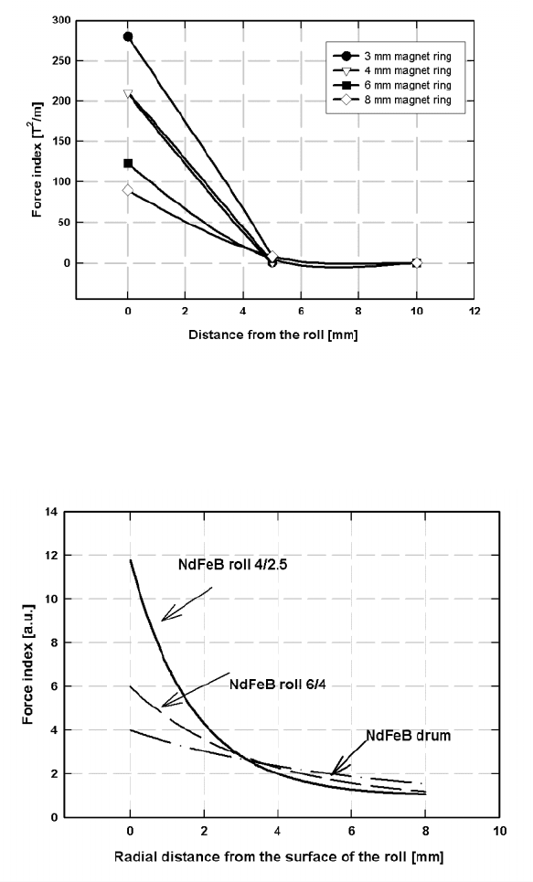
As can be seen in Figs. 4.42 and 4.43, for thin steel and magnet rings, which
generate a high force index close to the roll surface, the reach of the magnetic
force drops dramatically away from the surface. The rate of decrease is much
smaller for thicker magnet rings and even more so for an NdFeB drum.
Optimization of the design of the magnetic roll consists not only of maximiz-
ing the magnetic induction and force index on the roll surface and at a suitable
distance from the roll, but also of matching the dimensions of the magnet and
steel rings thicknesses to the particle size distribution of the material to be sep-
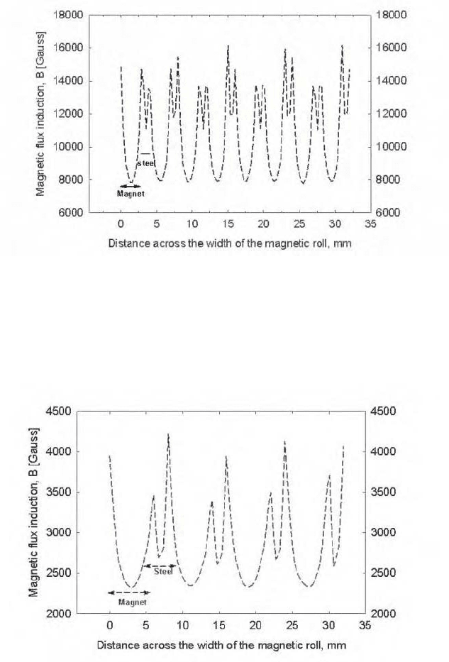
arated. Distributions of the magnetic induction along the axes of NdFeB and
SrFe rolls are shown in Figs. 4.44 and 4.45. The magnetic field (and magnetic
force) on the roll surface are the greatest in a relatively narrow region at the
interface between the magnet and steel rings. It can also be seen that the field
and the force along the circumference of the magnet rings are very feeble, and
it is imperative, therefore, that no particles are continuously exposed to this
region of the roll.
The thickness of the magnet rings should thus be of magnitude similar to the
294 CHAPTER 4. DESIGN OF MAGNETIC SEPARATORS
Figure 4.42: Force index as a function of distance from the roll surface, for
various thicknesses of magnet rings. Steel ring thickness equals 1
mm.
Figure 4.43: Force index (in arbitrary units), for two configurations of NdFeB
rolls and an NdFeB drum, as a function of the distance from the
surface of the roll [F18].
4.6. DESIGN OF A MAGNETIC ROLL 295
Figure 4.44: Distribution of the magnetic induction on the surface on an Nd-
FeB roll with 3/1 configuration (magnet thickness: 3 mm, steel
thickness: 1 mm).
Figure 4.45: Distribution of the magnetic induction on the surface of a SrFe roll
with 6/2 configuration (magnet thickness: 6 mm, steel thickness:
2mm).
296 CHAPTER 4. DESIGN OF MAGNETIC SEPARATORS
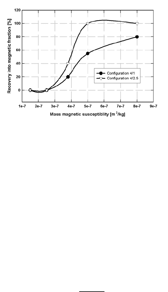
Figure 4.46: The partition curves for the recovery of 4 mm magnetic tracers by
NdFeB rolls of dierent configurations [F20].
mean particle size of the material to be separated. Thin magnet rings should
be used to separate fine particles, while for larger particles a thicker magnetic
ring oers a larger contact area with the roll, and a longer reach of the magnetic
force, of the order of the radius of the particles.
It transpires from the above discussion that the design of the roll, and specif-
ically the thicknesses of the magnetic and steel rings, is dictated by the magnetic
properties and size distribution of the feed. The roll design must be optimized in
order to maximize the magnetic force and its reach and to match the dimensions
of the particles with the magnet thickness. A specific configuration expressed as
magnet thickness/steel ring thickness is suitable only for a narrow size fraction
and typical configurations are summarized in Table 4.7.
The optimum configuration obtained by electromagnetic modelling can be
validated experimentally using magnetic tracers of suitable sizes and accurate
values of magnetic susceptibility. Magnetic partition curves can then be con-
structed, the probable error Hs can be calculated and a configuration with the
lowest Hs can be determined. Hs for a magnetic separator can be defined as
Hs =
"
75
"
25
2
(4.58)
where "
75
and "
25
are the mass magnetic susceptibilities of particles 75% and
25% of which, respectively, report to the magnetic fraction. Typical partition
curves, for 4 mm particles, are shown in Fig. 4.46. It can be seen that the
partition curve for the roll configuration 4/2.5 is steeper than that for 4/1
4.6. DESIGN OF A MAGNETIC ROLL 297
Table 4.7: Various configurations of NdFeB magnetic rolls. Configurations are
expressed as the ratio magnet thickness/steel thickness.
Configuration Size fraction Comment
3/1, 4/1 or 4.1.5 -5+0.1mm Short reach, high field
6/1.5, 6/2, 6/3 -10+5mm Longer reach, lower field
8/2, 8/3 +10mm For large particles
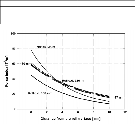
Figure 4.47: Force index for NdFeB rolls of dierent diameters, as a function
of distance from the roll surface. Roll configuration: 12/7.5. The
data were obtained by computer modelling (adapted from [F18]).
configuration and Hs is correspondingly lower. Configuration 4/2.5 is, therefore,
more selective in separating 4 mm particles of dierent magnetic susceptibilities.
Diameter of magnet rings
In the past, the diameter of a rare-earth magnetic roll was dictated by availabil-
ity of the largest magnetic rings. While the first commercial rolls had diameters
of 72 and 76 mm, recent progress in manufacture of rare-earth permanent mag-
net rings and segments allows for the manufacture of rolls with diameter of 100,
220 and 300 mm. The choice is determined by a combination of throughput,
performance and cost considerations. The present advantageous cost situation
favours larger diameter rolls, particularly when large throughputs are required
[A13].
In a simplified assumption of a constant magnetic force and constant resi-
298 CHAPTER 4. DESIGN OF MAGNETIC SEPARATORS
2a
1
2a
2
2a
3
h
z
P
H
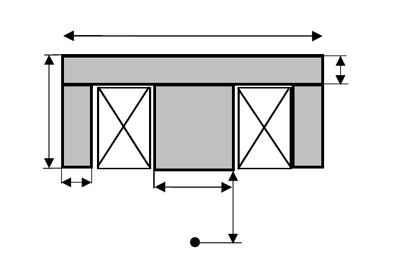
Figure 4.48: Schematic diagram of a suspended magnet.
dence time, a throughput increase by increasing the roll diameter, follows the
ratio G
1
/G
2
,whereG
1
and G
2
are the roll diameters, as follows from eq. (5.4).
It is sometimes argued that by increasing the magnet diameter the magnetic
force also increases and an even higher throughput can be expected. It appears,
however, that the increase in the magnet ring diameter above 100 mm brings
only negligible increase in the force index, as is illustrated in Fig. 4.47.
On the other hand, a longer retention time of particles in a larger-diameter
roll, as a result of a longer arc of the magnet ring, to which the particles are
exposed, allows for the increase of speed of rotation of the roll and thus for the
increase of the throughput, while maintaining constant residence time. Experi-
ence indicates that a throughput increase by factor of two to five, maintaining
the same performance, can be obtained with larger diameter rolls [A23, A13].
4.7 Design of a suspended magnet
Suspended magnets are usually installed over conveyor belts, discharge ends of
feeders or screens and above chutes or launders. Their design is dictated by
the burden depth, the belt speed, the clearance required over the burden and
the size, shape and mass of the tramp iron that is being removed. Strength
and reach of the magnetic field and of the magnetic force must, therefore, be
maximized for high e!ciency of the material removal.
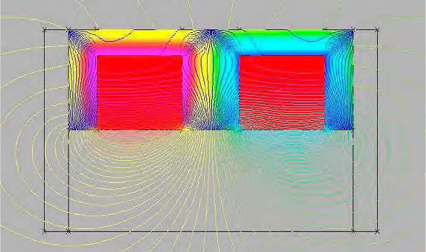
A schematic diagram of an electromagnet-based rectangular suspended mag-
net is shown in Fig. 4.48. The magnet consists of an iron yoke and a coil, which
magnetizes the yoke. The magnetic field generated at point S ,atdistance}
from the magnet, is the sum of contributions from the magnetized steel and
4.8. DESIGN OF A FERROHYDROSTATIC SEPARATOR 299
Figure 4.49: Pattern of magnetic flux around a suspended magnet.
the coil. Dimensions of individual parts of the yoke determine the distribution
of the magnetic field and magnetic force, their value and reach. Using com-
puter modelling, it is possible to investigate the influence of these dimensions
and to determine the optimum design for a given application. The distribution
of magnetic flux around a suspended magnet is shown in Fig. 4.49, while a
three-dimensional image is presented in Fig. 4.50.
In commercially available suspended magnets, the width 2d
1
of the magnet
typically ranges from 900 mm to 1400 mm, the depth ranges from 700 mm to
1250 mm and the height K is around 500 mm.
Aluminium is the preferred conductor materials, mainly because of its lower
density. For the same electric power, the mass of the aluminium coil can be
approximately halved, compared with the copper coil [K36]. In addition, the
use of the aluminium foil, rather than of the wire, allows for the increase in
the filling factor of the winding, by about 40% [K36]. As a result, the number
of ampere-turns can be reduced, or, alternatively, at the constant number of
ampere-turns, a more powerful magnet can be constructed.
4.8 Design of a ferrohydrostatic separator
Commercial and laboratory ferrohydrostatic separators use either an electro-
magnet or permanent magnets to generate the magnetic field in the working
space. Of fundamental importance in the operation of separators with magnetic
fluids are the characteristics of the magnetic levitation force, expressed by the
second term on the right-hand side of equation (2.9), namely by M
i
EuE.These
characteristics are determined by the pattern of the gradient of the magnetic
