Jan Svoboda. Magnetic Techniques for the Treatment of Materials
Подождите немного. Документ загружается.

260 CHAPTER 4. DESIGN OF MAGNETIC SEPARATORS
L
g
a
A
g
Permanent
magnet
Mild steel
y
oke
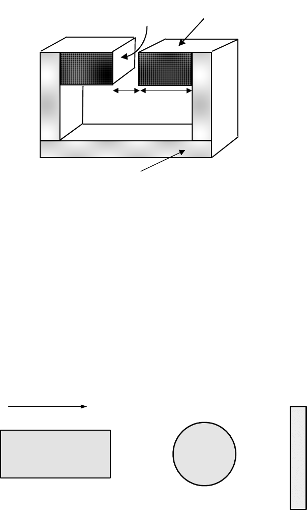
Figure 4.6: A permanent magnet circuit for the calculation of the leakage coef-
ficient.
note that a thin disc magnetized through its thickness produces no magnetic
flux density although the magnetic field strength K at point C is equal to M@
0
.
Calculation of the magnetic field around a permanent magnet can be per-
formed either using the pole concept or the surface current models. In the
former approach a magnet is treated as having a uniform distribution of poles
on the ends of the magnet. Using this assumption, magnetic induction on the
} axis of a circular infinitely long magnet, as a function of the distance from the
B C D B C D
C
A E A
E
AE
H
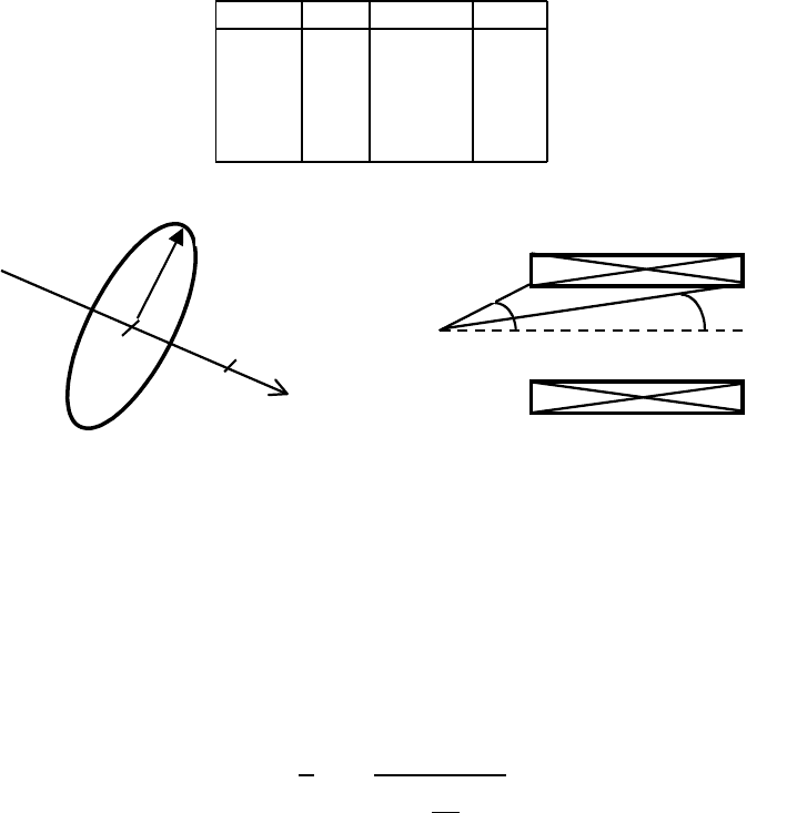
Figure 4.7: Distribution of magnetic induction inside and outside magnets of
various shapes.
4.2. DESIGN OF CIRCUITS WITH PERMANENT MAGNETS 261
Table 4.2: Distribution of magnetic induction B inside and outside magnets of
various shapes [H18].
Point Bar Sphere Disc
A J/2 2J/3 0
B J/2 2J/3
C J 2J/3 0
D J/2 2J/3
E J/2 2J/3 0
P
R
z
ș
1
ș
2
P
(a)
(b)
Figure 4.8: Calculation of magnetic induction on the axis of a cylindrical mag-
net.
magnet (Fig. 4.8), is given by
E
}
=
M
2
5
9
9
9
7
1
}@U
µ
1+
}
2
U
2
1@2
6
:
:
:
8
(4.26)
where U is the radius of the magnetic cylinder. By symmetry, E has no com-
ponents perpendicular to }= It can be seen that on the surface of the magnet
(} =0)the magnetic induction E = M@2, as shown in Table 4.2. Numerical
computations are required to determine the magnetic induction o the axis.
Expressions similar eq. (4.26) can also be obtained for the components of mag-
netic induction generated by rectangular surfaces [M19].
A uniform solenoid of rectangular or circular cross-section with surface
current density m
v
(A/m) is equivalent, for the purpose of calculating magnetic
induction, to a bar with uniform magnetization P = m
v
= M@
0
. If a solenoid
has a circular cross-section, magnetic induction E> at point S on its axis, is
262 CHAPTER 4. DESIGN OF MAGNETIC SEPARATORS
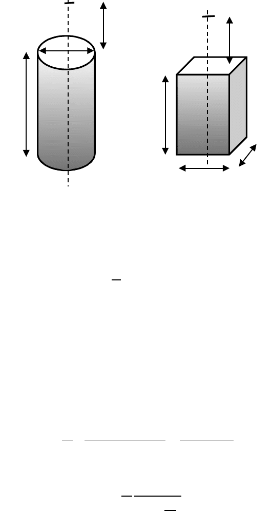
Figure 4.9: Definition of geometrical parameters of a cylindrical and a rectan-
gular permanent magnets for calculation of the magnetic field.
given by
E =
0
m
v
2
(cos
1
cos
2
) (4.27)
It can be seen that on the surface of an infinitely long solenoid (
1
=0,
2
=
90
0
) E =
0
P@2, as could have been expected.
Selvaggi and Selvaggi [S48] developed mathematical equations that allow
the external and internal magnetic fields of cylindrical and rectangular perma-
nent magnets of finite dimensions to be determined. These magnets are shown
schematically in Fig. 4.9. The authors assumed that the surface charge density
at the poles is equal to M
u
and that only two parallel faces contribute to the
field.
The equation for the external field at distance } from the face of a circular
magnet of radius U and length O is
E
h{w
=
M
u
2
(
} + O
[U
2
+(} + O)
2
]
1@2
}
[U
2
+ }
2
]
1@2
)
(4.28)
The equation of the internal field, at the centre of the magnet is
E
lqw
= {
M
u
2
O
(U
2
+
O
2
4
)
} (4.29)
Clearly, for O $4, E
lqw
$ M
u
.
It can be seen that both terms in parentheses in eqs. (4.28) and (4.29) are
dimensionless and thus any system of units can be used.
z
2R
L
z
L
D
W

4.2. DESIGN OF CIRCUITS WITH PERMANENT MAGNETS 263
Similar expressions were derived for a rectangular permanent magnet of finite
dimension, as defined in Fig. 4.9. The equation for the external field is
E
h{w
=
M
u
;
A
A
A
A
A
A
A
?
A
A
A
A
A
A
A
=
arcsin
ZG
4
·
(
Z
2
4
+ }
2
)(
G
2
4
+ }
2
)
¸
1@2
arcsin
ZG
4
·
(
Z
2
4
+(} + O)
2
)(
G
2
4
+(} + O)
2
)
¸
1@2
<
A
A
A
A
A
A
A
@
A
A
A
A
A
A
A
>
(4.30)
while the expression for the internal field is given by
E
lqw
=
M
u
;
A
?
A
=
2 arccos
5
9
7
ZG
4[(
Z
2
4
+
O
2
4
)(
G
2
4
+
O
2
4
)]
1@2
6
:
8
<
A
@
A
>
(4.31)
Considerably more complicated expressions for the o-centre magnetic field can
also be found in [S48]. Good agreement between the measured values and those
determined from eqs. (4.28) to (4.31) was found.
4.2.6 Magnetic forces
Permanent magnet circuits can be designed either for holding magnetic bodies
or for attracting them. The distinction is that the holding magnet has to exert
a magnetic force on a material with which it makes a good contact, while the
attracting magnet has to exert a force on a magnetic body at a considerable
distance. The distinction is important, because the optimum design for the two
purposes diers considerably.
While the attraction force is essential in many forms of magnetic separators,
such as suspended magnets or wet low-intensity drum magnetic separators, in
other types of separators it is the holding force that plays a decisive role. The
correct compromise between holding and attracting particles from a distance
must be achieved.
A force between two magnetic charges T
1
and T
2
separated by a distance u
is given by Coulomb’s magnetostatic law:
I =
T
1
T
2
4
0
u
2
u
0
(4.32)
where u
0
is the unit vector in the direction of u= For a thin cylindrical magnet
T = MD where M is the magnetic polarization and D is the cross-sectional area
of the magnet. We can then write, for semi-finite magnetic bars of the same
cross-sectional area D
I =
1
4
0
u
2
M
d
M
e
D
2
u
0
(4.33)

264 CHAPTER 4. DESIGN OF MAGNETIC SEPARATORS
where M
d
and M
e
are magnetic polarizations of bars d and e, respectively. When
these bars are in contact, eq. (4.33) reduces to:
I =
1
2
0
M
d
M
e
D (4.34)
As an example, magnetic polarization of 1 T produces a pull of 40 N/cm
2
,or
approximately 4 kg/cm
2
, while 0.2 T creates a pull of a mere 0.16 kg/cm
2
.
Equation (4.34) is often simplified even further, under the assumption M
d
=
M
e
= E> into the form
I =
1
2
0
E
2
D (4.35)
which is incorrect in many instances [M19]. For instance, if M
e
=0, then cor-
rectly I =0> according to eq. (4.34). The simplified formula would incorrectly
yield I = M
2
d
D@8
0
. Generally, eq. (4.35) is valid only when bars d and e are
of the same material and when there is no source of external magnetic field.
It is obvious from eqs. (4.34) and (4.35) that the holding force is proportional
to the square of flux density and only to the first power of the magnet area. By
using tapered soft-iron pole-tips it is possible to concentrate the flux to a higher
density than the magnets themselves can provide. Although the cross-sectional
area of the magnet would decrease somewhat, the holding force will increase
nevertheless.
Although by increasing the magnetic flux it is possible to increase the holding
force for zero air gap, the reach of the magnetic force would decrease once the
air gap is introduced. The force of attraction would thus decrease. Therefore,
in those magnetic separators in which a pull at a distance (traction force) is
important, wide pole-pieces working at a low induction and allowing high force
penetration into the air gap, are required. On the other hand, closely spaced
poles that produce high holding force are incorporated into those magnetic sep-
arators that rely on the holding force rather than traction force. Dry drum and
roll magnetic separators are an example of such machines.
4.2.7 Soft iron components of the magnetic circuits
Pole-pieces of a solid or laminated soft iron or mild steel , or occasionally cobalt-
iron, are an essential part of magnet design. These flux-conducting members
are used to complete a return path for the flux and to concentrate or change
the flux density in a circuit. Cost is usually an important factor in the choice
and majority of magnetic circuits use ordinary cold-rolled steel for these com-
ponents. Cobalt-iron alloy is used in some high-performance circuits. It is a
good practice to operate these materials near their maximum permeability, as
shown in Fig. 1.9. This will ensure the maximum flux-carrying capacity of the
circuit. Magnetization curves for some high-permeability materials is shown in
Fig. 4.10.
Relative position of permanent magnets and mild steel components is also
of significant importance. Figure 4.11 illustrates three possible arrangements
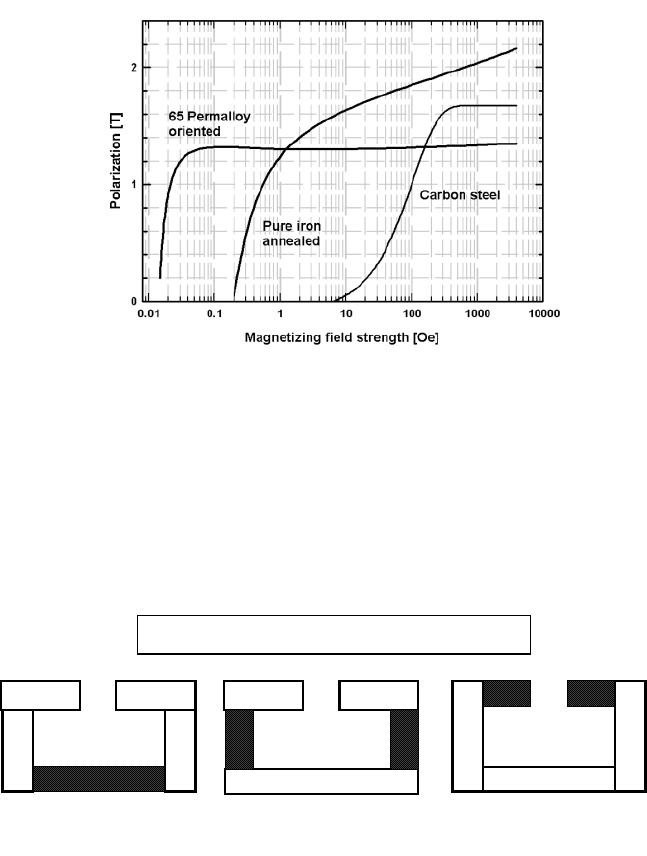
4.2. DESIGN OF CIRCUITS WITH PERMANENT MAGNETS 265
Figure 4.10: Magnetization curves for several high-permeability materials.
(a)
(b)
(
c
)
Three positions of permanent magnets in a circuit
Figure 4.11: Three arrangements of a circuit with permanent magnets.

266 CHAPTER 4. DESIGN OF MAGNETIC SEPARATORS
Table 4.3: Reversible temperature coe!cients of permanent magnetic materials.
Material (B
u
) [%/
0
C] (H
fl
) [%/
0
C]
Ferrite -0.20 +0.40
SmCo
5
-0.04 -0.30
NdFeB -0.12 -0.60
of a circuit with permanent magnets. Arrangement (a) is the least e!cient
as the leakage between the circuit elements is very high. On the other hand,
arrangement (c) is the most e!cient as a result of low leakage. Analysis of these
circuits with an Alnico 5 magnet showed that the ratio of the gap flux to the
total flux in the arrangement (c) is three times higher than in arrangement (a)
[P12]. It is clear that permanent magnets should be placed as close to the air
gap as possible. A valuable advantage can be obtained by placing a magnet,
magnetized through its thickness, on a ferromagnetic plate. Then the magnet
behaves like one of twice its thickness.
4.2.8 Stability of permanent magnets
Permanent magnets are expected to maintain a constant flux output over a
long period of time, although any magnet, after being fully magnetized, is likely
to lose strength slowly with time. In nearly all applications the magnet is
subject to influences that tend to alter the magnet flux. However, in contrast
to early permanent magnets, the modern materials exhibit remarkable stability,
sometimes as high as 10
6
.
Reversible changes
The magnetization changes fall into two classes, namely reversible changes and
irreversible changes. The reversible changes in the magnetic properties, as
a function of temperature, originate in the change in spontaneous magneti-
zation. Reversible changes are functions of temperature and circuit loading
and are time-independent. They disappear completely without need for re-
magnetization when the permanent magnet is returned to its initial tempera-
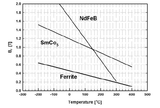
ture. Figure 4.12 illustrates the dependence of the remanent magnetization on
temperature for three types of permanent magnet materials.
The reversible changes resulting from temperature changes can be repre-
sented by temperature coe!cients, expressed as a percentage change in M or E
per
0
C. A summary of the temperature coe!cients of E
u
and K
fl
for sev-
eral permanent magnet materials is given in Table 4.3. In addition, Table 1.18
summarizes the Curie temperatures and maximum operating temperatures of
various permanent magnet materials.
In many instances the temperature coe!cients of magnetization and coer-
cive force do not give enough information about how a magnet will respond to
temperature changes. Changes in the shape of a demagnetization curve and the
4.2. DESIGN OF CIRCUITS WITH PERMANENT MAGNETS 267
Figure 4.12: Temperature dependence of remanent magnetization of various per-
manent magnetic materials (adapted from [P4]).
position of the load line and the working point can only be seen from a complete
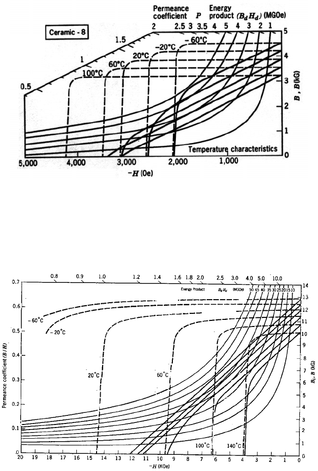
set of demagnetization curves, measured at dierent temperatures. Figures 4.13
and 4.14 illustrate families of demagnetization curves at various temperatures
for ferrite and NdFeB permanent magnets. Such curves are useful for graphical
design of magnets operating under various temperature conditions.
Complete sets of such demagnetization curves are available either in the
literature (e.g. [P4]) or the most recent data can be obtained directly from
magnet manufacturers.
Irreversible changes
In the case of irreversible changes, after the removal of the disturbing influence,
the magnetization does not return to its original value. In certain types of
changes however, the magnetization can be fully restored by re-magnetization.
Such changes are, for instance, ambient temperature changes and exposure to
an external magnetic field. Upon exposure to an external field, the operating
point moves down the demagnetization curve and the intrinsic magnetization
of the magnet shows a corresponding change. When the external field is re-
moved, the magnetization recovers only partially. This loss is recoverable by
re-magnetization. The loss will be greater when a magnet is operating in the
steepest part of the demagnetization curve.
Although mechanical shock and vibration contribute energy to a permanent
magnet, changing its magnetization, modern materials with high coercive forces
seem to be resistant to changes by mechanical eects. At the same time, how-
ever, field exposure is not able to completely eliminate changes that might have
occurred.
268 CHAPTER 4. DESIGN OF MAGNETIC SEPARATORS
Figure 4.13: Demagnetization curves of a ferrite magnet at dierent tempera-
tures.
Figure 4.14: Demagnetization curves of an NdFeB magnet at various tempera-
tures.

4.2. DESIGN OF CIRCUITS WITH PERMANENT MAGNETS 269
Table 4.4: Magnetic induction required to magnetize permanent magnet mate-
rials.
Material B
vdw
[T]
Alnico 5 0.3
Alnico 8 0.8
Ferrite 1.0
RECo
5
2.0 to 3.0
NdFeB 2.5 to 3.0
While Alnico and ferrite magnets are stable and not subject to corrosion,
rare-earth magnets have oxidation problems that limit their maximum operating
temperature. If no coating is provided for protection, oxygen diuses into such a
magnet, causing a metallurgical change in a surface layer. The surface layer will
have a lower K
fl
, which will allows this region of the magnet to be demagnetized
more easily. Surface oxidation thus leads irreversibly to a reduction in the
magnetic properties.
Irreversible changes, resulting from permanent changes in the structural or
metallurgical state, are usually time-dependent and re-magnetization does not
restore the original state of magnetization. The temperature at which changes
in properties first become noticeable corresponds to the maximum operating
temperature. Temperature-induced irreversible losses in permanent magnets
are shown in Table 1.17.
4.2.9 Magnetization of permanent magnets
It is generally accepted that to magnetize a permanent magnet to saturation,
an external magnetic field three to five times its intrinsic coercivity K
fl
must be
applied. Typical values of the magnetic induction required to magnetize various
permanent magnet materials are summarized in Table 4.4.
Simple bar or ring-shaped magnets may be magnetized by a larger perma-
nent magnet, a solenoid or an electromagnet. To magnetize rare-earth magnets,
very high fields are required and magnetization is often performed with small
coils or solenoids energized by large current pulses of short duration. Large mag-
nets cannot be magnetized by a pulse of short duration, because eddy currents
prevent the flux reaching the centre of the magnet. In general, the frequency i
of the pulse must be chosen so that the magnetizing pulse lasts longer than the
eddy current. The depth of penetration, or the skin depth ,isgivenby
=
µ
(
0
i
1@2
(4.36)
where ( is the resistivity of the material.
Resistivity plays a very important role since most permanent magnets have
very low permeabilities . Ceramic ferrite magnets have high resistivity (A
10
4
m and full penetration of a pulse is easy. On the other hand, Alnico and
