Jackson M.J. Micro and Nanomanufacturing
Подождите немного. Документ загружается.

502 Micro- and Nanomanufacturing
ELEMENTS
HAT
HUM
•
tt^^^^,..,,
i
m
AN
JUL
8
2003
10:25:41
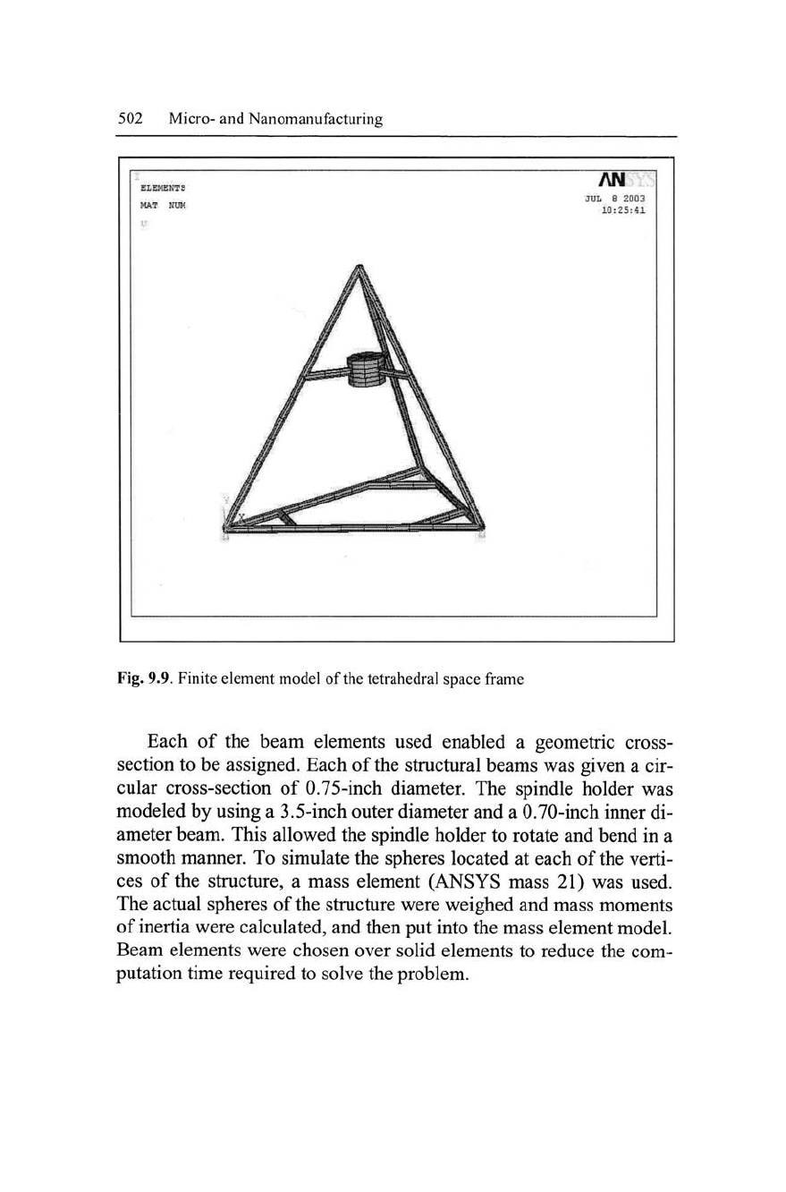
Fig. 9.9. Finite element model of the tetrahedral space frame
Each
of
the beam elements used enabled
a
geometric cross-
section to be assigned. Each of the structural beams was given a cir-
cular cross-section
of
0.75-inch diameter. The spindle holder was
modeled by using a 3.5-inch outer diameter and a 0.70-inch inner di-
ameter beam. This allowed the spindle holder to rotate and bend in a
smooth manner. To simulate the spheres located at each of the verti-
ces
of
the structure,
a
mass element (ANSYS mass 21) was used.
The actual spheres of the structure were weighed and mass moments
of inertia were calculated, and then put into the mass element model.
Beam elements were chosen over solid elements to reduce the com-
putation time required to solve the problem.
Micromachining Using Pulsed Water Droplets 503
9.8.2 Closed-Form Solution Model
Sample calculations were performed to approximate the dynamic re-
sponse of the tetrahedral structure. The purpose of these calculations
is to obtain a continuous model of the structure instead of a finite
element approximation. The structure was modeled as four spheres
at each of the vertices of the tetrahedron, with springs simulating the
structural links between them. Equation 9.36 was the equation used
to generate a mathematical model of the structure.
[M]*X+[K]*X = 0 (9.36)
Where, [M] is the matrix of masses for each sphere, Xis the
acceleration of each sphere,
[
K
]
is the stiffness matrix for all of the
structural links, andX is the displacement of each sphere. Equation
9.37 was used to model the stiffness (K) of each connecting rod
(axial displacements are considered in this formulation to decrease
the complexity of the solution):
A*
F
K=^-^
(9.37)
Where A is the cross-sectional area, E is Young's modulus of
elasticity, and
1
is the length of the beam. Since this structure was
modeled as a 9 degree-of-freedom (d.o.f.) system, the methods listed
by Inman [21] were used. This method assumes that each of the
d.o.f.'s can be modeled by the superposition of several single
d.o.f.
systems. The structure is a three-dimensional structure, in which
each equation had to be related to a global coordinate system similar
to the methods used in finite element formulations. There were 3 de-
grees of freedom for the top sphere and 2 degrees of freedom for the
base spheres, which led to 9 possible natural frequencies. Damping
was not considered in the mathematical modeling of this structure
because it would create more difficulty in solving the equations.
504 Micro- and Nanomanufacturing
9.9 Mode Shapes of Tetrahedral Structures
The impact hammer test has become a widely used device for de-
termining mode shapes. The peak impact force is nearly proportional
to the mass of the head of the hammer and its impact velocity. The
load cell in the head of the hammer provides a measure of the impact
force. This data is used to compute the frequency response function
(F.R.F.).
The use of an impact hammer avoids the mass-loading
problem and is much faster to use than a shaker. An impact hammer
consists of a hammer with a force transducer built into the head of
the hammer. The hammer is used to impart an impact to the structure
at designated points of the structure and excite a broad range of fre-
quencies. The impact event is supposed to approximate to a Dirac-
delta function [22].
9.9.1 Experimental Method
The tetrahedral structure was placed on a granite table in order to
gain accelerometer measurements, thus the structure was allowed to
freely move longitudinally and transversely across the table. The
roving accelerometer approach was used for all of the measure-
ments. The center of the spindle frame was used as the excitation
point for the structure. The accelerometer was placed at various
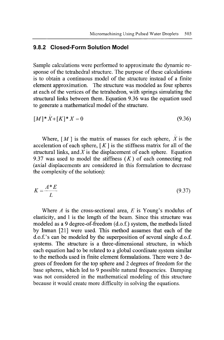
points of interest about the structure. Figure 9.10 shows the experi-
mental structure and the impact hammer used to excite the structure.
9.9.2 Experimental Procedure
The data acquisition system was set up to take data at a sampling
frequency, F
s
, of 17,000 Hz for 8192 points with a delay of 100
points. The voltage range on both channels was set to +\- 5 volts.
Data was acquired in the time domain by averaging 8 ensembles and
storing the data in binary format. This data was used to find the
natural frequencies of the structure and their corresponding mode
shapes.
Micromachining Using Pulsed Water Droplets 505
Fig. 9.10. Tetrahedral structure showing marked points of vibration measurement
and the impact hammer used to excite the structure
While applying the roving accelerometer technique, the structure
was excited in the center of the spindle sub-frame and data were ac-
quired at points 1-28. Before the time domain data was stored, it was
filtered to remove any aliasing that might have occurred from under-
sampling. This was accomplished by installing an analog filter be-
tween the power supply and the P.C. The frequency was set at 8500
Hz, which corresponds to the Nyquist frequency of the measured
data. After the data were recorded, they were translated into a binary
file.
506 Micro- and Nanomanufacturing
Compliance
magnitude
Him)
3
\7
i
o
CI
' 10 *• 20 30 40
Driving frequency
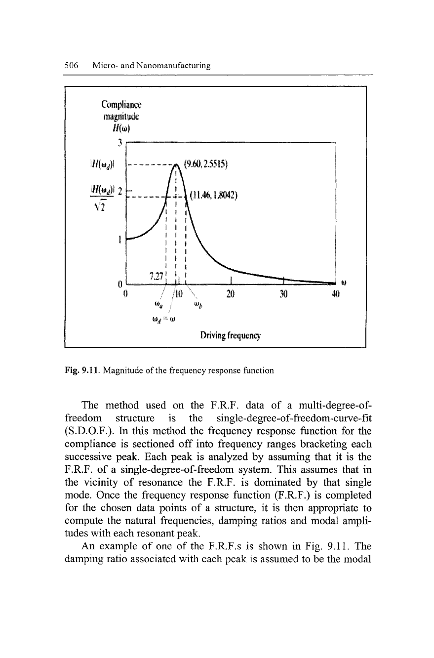
Fig. 9.11. Magnitude of the frequency response function
The method used on the F.R.F. data of a multi-degree-of-
freedom structure is the single-degree-of-freedom-curve-fit
(S.D.O.F.). In this method the frequency response function for the
compliance is sectioned off into frequency ranges bracketing each
successive peak. Each peak is analyzed by assuming that it is the
F.R.F. of a single-degree-of-freedom system. This assumes that in
the vicinity of resonance the F.R.F. is dominated by that single
mode. Once the frequency response function (F.R.F.) is completed
for the chosen data points of a structure, it is then appropriate to
compute the natural frequencies, damping ratios and modal ampli-
tudes with each resonant peak.
An example of one of the F.R.F.s is shown in Fig. 9.11. The
damping ratio associated with each peak is assumed to be the modal
|~-- —
LJJII
-
A
(9.60,2,5515)
• \
J-W11.4MJJD42)
* \
* t \
t i \
1
* \ 1
I I \ i
tl
1 1
^^
mm
*~**l>-
^J
Micromachining Using Pulsed Water Droplets 507
damping ratio, zeta (<f). The modal damping ratio zeta is related to
the frequencies corresponding to Eq. 9.38.
\H{oy
a
)\ = \H{co
b
)\=^^-
(9.38)
And co
b
-co
a
-
2£a>
d
,
so
that
C
=
^^L (9.39)
2(o
d
W
d
is the damped natural frequency at resonance such that co
a
and co
h
satisfy Eq. 9.38. The condition of Eq. 9.39 is termed the 3
dB down point. Both the natural frequency and the damping ratio
Zeta may be found via this method. Once the values of
co
a
and co
h
are determined, then
<^
is found for the structure at the prescribed
frequency (Eq. 9.39). This method was used in the software to ex-
perimentally determine the damping and mode shapes. Figure 4
gives an example of
F.R.F.
data set that was found from the tetrahe-
dral structure.
9.9.3 Experimental Analysis
Using the measured data obtained from Me-Scope software, a model
(Figure 9.13) was constructed and the data were used to find struc-
tural damping and mode shapes. At first it was thought that the data
were too low because the operating frequencies of the spindle are
above 4500 Hz. However the operating frequencies of the spindle
could excite lower frequencies while machining. Therefore, these
data are useful if the structure is excited at these frequencies by
some other means, such as localized impacts the structure might ex-
perience during a machining operation. This is shown in the follow-
ing series of illustrations at the chosen frequencies (Figs. 9.14 -
9.19).
508 Micro- and Nanomanufacturing
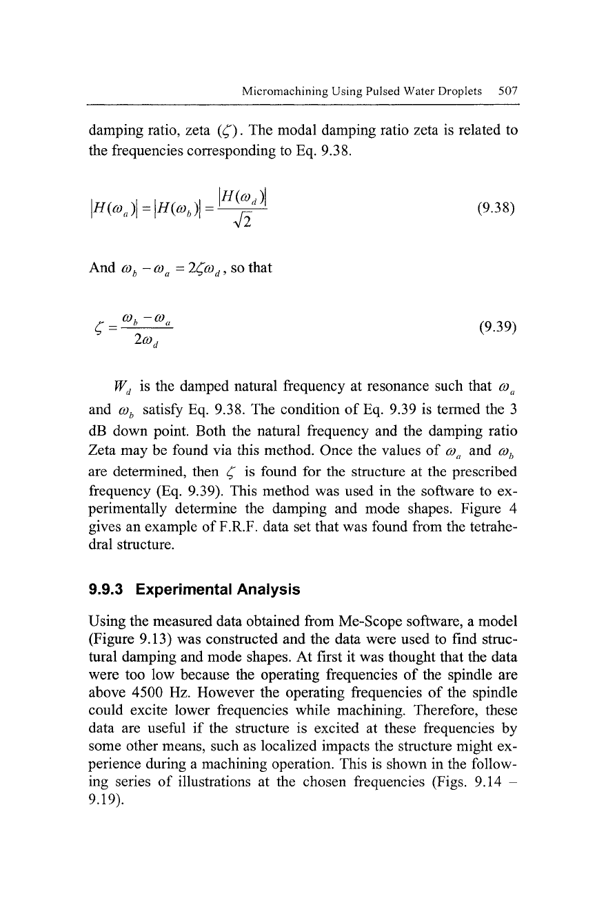
The measured data for each node was adjusted such that the axis
of orientation corresponded with the orientation of the accelerome-
ter.
Fig. 9.12. F.R.F. data set cut off at 5000 Hz
Micromachining Using Pulsed Water Droplets 509
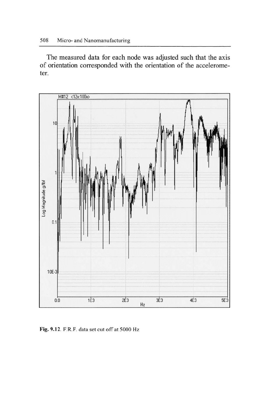
Fig. 9.13. Schematic diagram of the tetrahedral space frame showing experimental
points-of-measurement for determining mode shapes
Figure 9.13 illustrates where mode shape measurements were
taken during the experimental phase of this study (numbers 1-28
represent actual data points, whereas the other numbers were used
for interpolation between measurement points).
510 Micro-and Nanomanufacturing
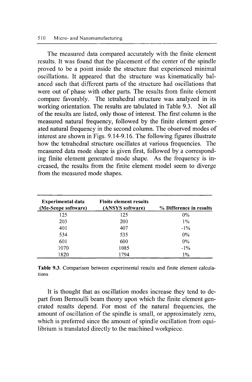
The measured data compared accurately with the finite element
results. It was found that the placement of the center of the spindle
proved to be a point inside the structure that experienced minimal
oscillations. It appeared that the structure was kinematically bal-
anced such that different parts of the structure had oscillations that
were out of phase with other parts. The results from finite element
compare favorably. The tetrahedral structure was analyzed in its
working orientation. The results are tabulated in Table 9.3. Not all
of the results are listed, only those of interest. The first column is the
measured natural frequency, followed by the finite element gener-
ated natural frequency in the second column. The observed modes of
interest are shown in Figs. 9.14-9.16. The following figures illustrate
how the tetrahedral structure oscillates at various frequencies. The
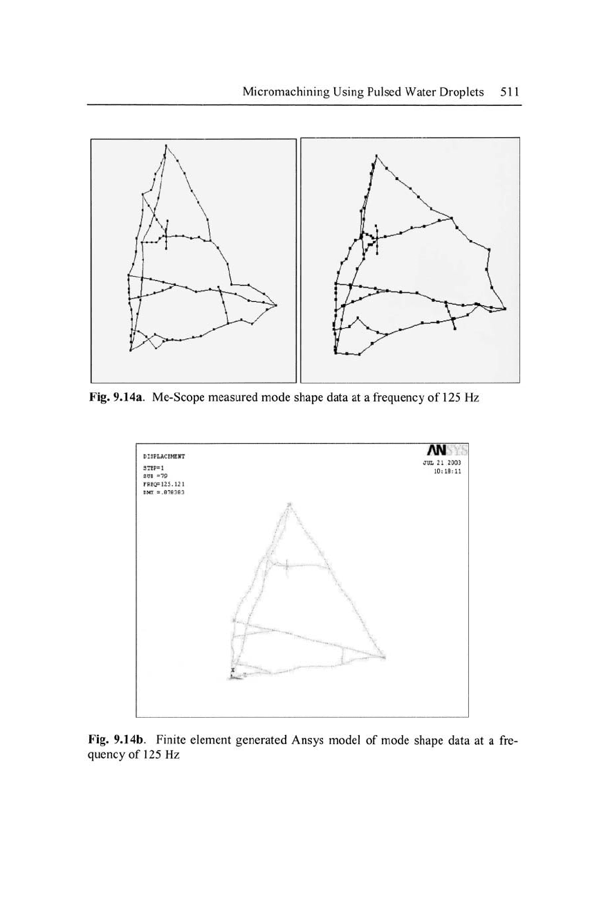
measured data mode shape is given first, followed by a correspond-
ing finite element generated mode shape. As the frequency is in-
creased, the results from the finite element model seem to diverge
from the measured mode shapes.
Experimental data Finite element results
(Me-Scope software) (ANSYS software) % Difference in results
125 125 0%
203 200 1%
401 407 -1%
534 535 0%
601 600 0%
1070 1085 -1%
1820 1794 1%
Table 9.3. Comparison between experimental results and finite element calcula-
tions
It is thought that as oscillation modes increase they tend to de-
part from Bernoulli beam theory upon which the finite element gen-
erated results depend. For most of the natural frequencies, the
amount of oscillation of the spindle is small, or approximately zero,
which is preferred since the amount of spindle oscillation from equi-
librium is translated directly to the machined workpiece.
Micromachining Using Pulsed Water Droplets 511
Fig. 9.14a. Me-Scope measured mode shape data at a frequency of 125 Hz
Fig. 9.14b. Finite element generated Ansys model of mode shape data at a fre-
quency of 125 Hz