Indian National Committee on Large Dams. Design and Construction Features of Selected Dams in India
Подождите немного. Документ загружается.

TapJr,r
l)um
Performanee
of
partial
catoff
in
rrniforno
sand
Synopsis
1.0
fntroduction
(i)
Concrete
diaphragm
for
the
entire
pervious
depth.
(fr)
Positive
cut_off
for part
depth and
sheet
pile
partial
curoff
for
the
iirt
of
depth.-
(tii)
Partial
cutofffor-
part
depth,
supplemented
by
impervious
blank'et
;;'upstream
and
relief
wells
on
downstream
*itr,
ippr"pri"rJli."k
on
the
value
of
exit
graOieni.
The
lasr
alternative
of
partial
cutoff
with
a
blan-
ket
and
retief
wells
;;r
frila
i"onooricar
and
invesri-
gated
further.
2.0
Foundation
The
location
<
ieads-i6
p;;i;;r
sandY.
foundation
"nO
biii"g]'"^ e
la'
uplift
pressures
studied
^in
?etail
were,
therefore,
;i";;d'or|o.r
r
floundation
condi-
vere
worked
out.
rection
alons
the
dam
axis
showing
from
ch.
si
qri:oo
f,)it"Lh
244m
:
p-orrion
.is
given
in
pigu.e
--i.
The
:epest
section
is
at
R.LI
of
27.40
m
'
Iayer
occurs
ut
n..r.
ij.o
*
i+o.o
rrl
,1g-
cr.av.
rqy.f
*jtr'::,t:-;:t,fi
;'.""'ir'
diJJJ,$
cemented
called
,l1nd
i."d-
The
partial
cutoff
rests
on
this
sand
rock.
The
name
sand
-.k
i,
,uih;;;iri;ading,
321
o
9n
'.-
$
o.:,,
.,,ogo
5
3r*
ONtlJl
o
.
og
o
H:
gp
:
o
o6
o
(v
c
/
t3
gt
o
rO
o
.r;
ge
Ofr
3
,';
o
.16
I
tO
'l
4
a
22
R.L
43 28m
€€rlh don
rifh
Portrol
COT
7,2
tz
dt
40
ES L 4O-t9r
39
30
E
23
c
r
20
!
rt
l5
o
I
J
!
tO
o
c
tos Gl
F6
4'
Ground
\t
V
(v
lFvet'nm
a!l
t
()rl
o
O()
33333giPBa [.,-.S
g
I
I
o
t
3
g
-
@
.l
o
*
og
J)
6
r.
f I
q
o|
or
o
CD
F
o
o|
S
(r)
ra
fi
't Gril
rrr
.aq
N
A
i|
\l
(,
(o
-vr
o ."
o o
88
on
o{
()9
.o
(
eh:i1sc.
et:
i[
s
;
*Hi.r[
e ;[
H$
q
e ;
q-
q
q
$
[
g
$
i R
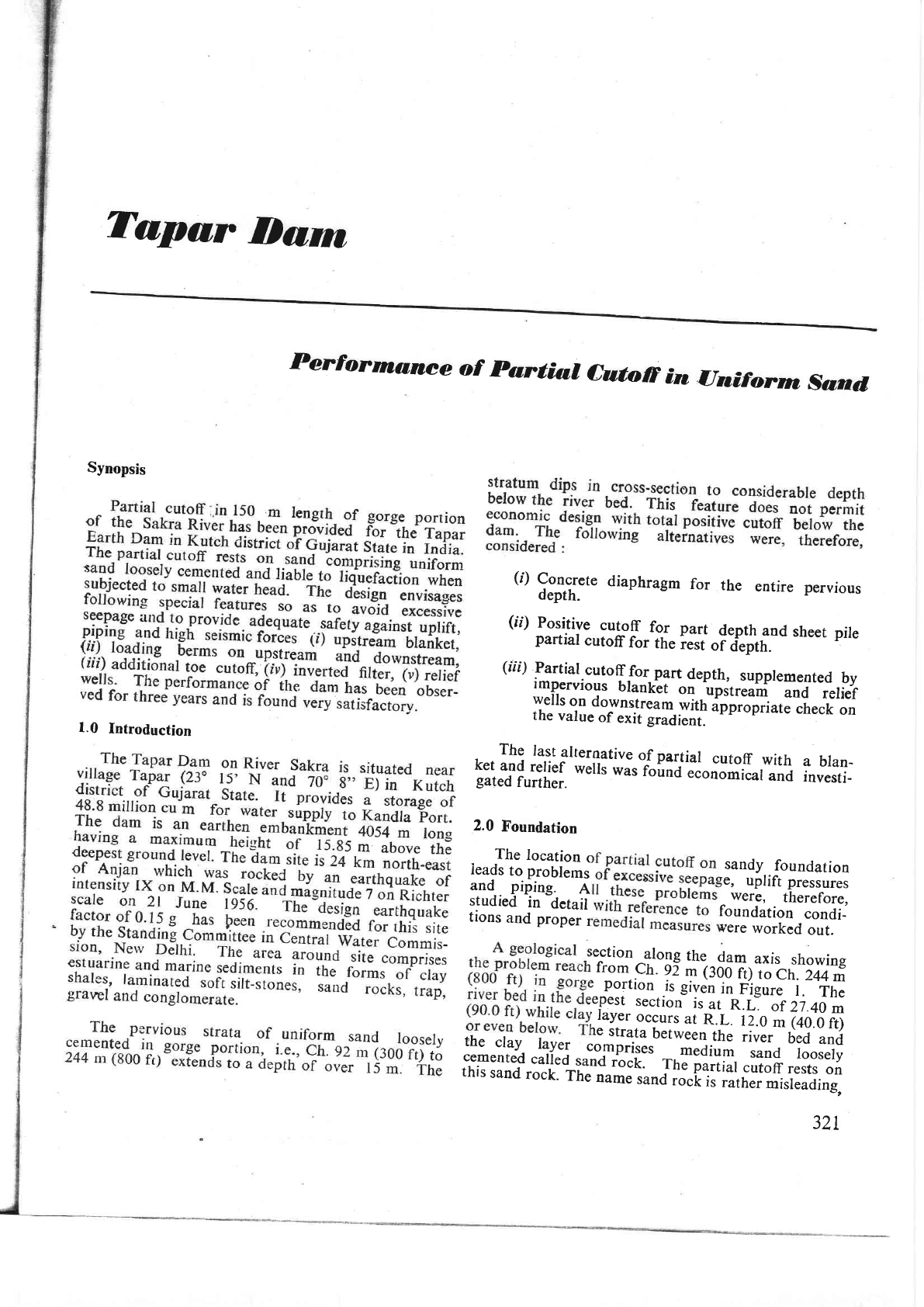
FIGURE
I :
Longitudinal
section
showing sub-surface
geology
along dam
alignment
of
Tapar
Reservoir
project.
T-g-=
_$
(?
I
.t
because
it actually
consists
of sand
particles
of
O.2to
0.4
mm size
loosely cemented.
The
cementing
effect is so
negligible
that
the rock
mass
crumbles
even
with
a finger
touch.
The
M.A.
curves of
li
samples
of this
sand
rock
are
given
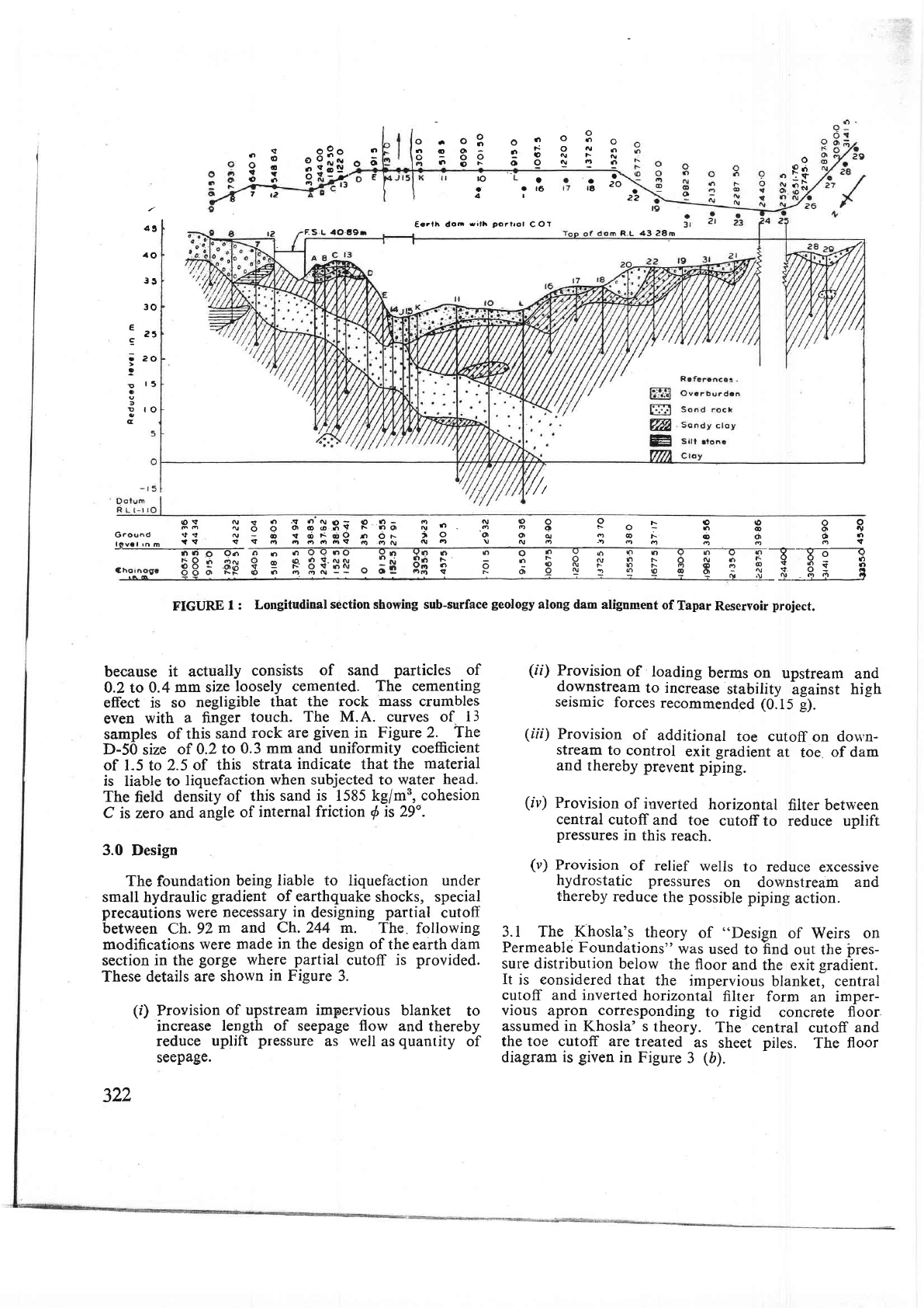
in Figure 2. The
D-50
size
of
0.2
to
0.3
mm
and
uniformity coefficient
of
l-5 to
2.5 of
this
strata
indicate that the
material
is
liable to
liquefaction
when subjected
to
water
head.
The
field
density
of this
sand is 1585 kg/m3,
cohesion
C is zero
and
angle
of
internal
friction
{
is
29'.
3.0
Design
The
foundation
being
liable
to liquefaction under
small hydraulic
gradient
of earthquake
shocks, special
precautions
were
necessary
in
designing
partial
cutoff
between
Ch. 92
m and
Ch.
244 m.
The
following
modificatio,ns
were
made
in
the design
of
the earth dam
section
in
the
gorge
where
partial
cutoff is
provided.
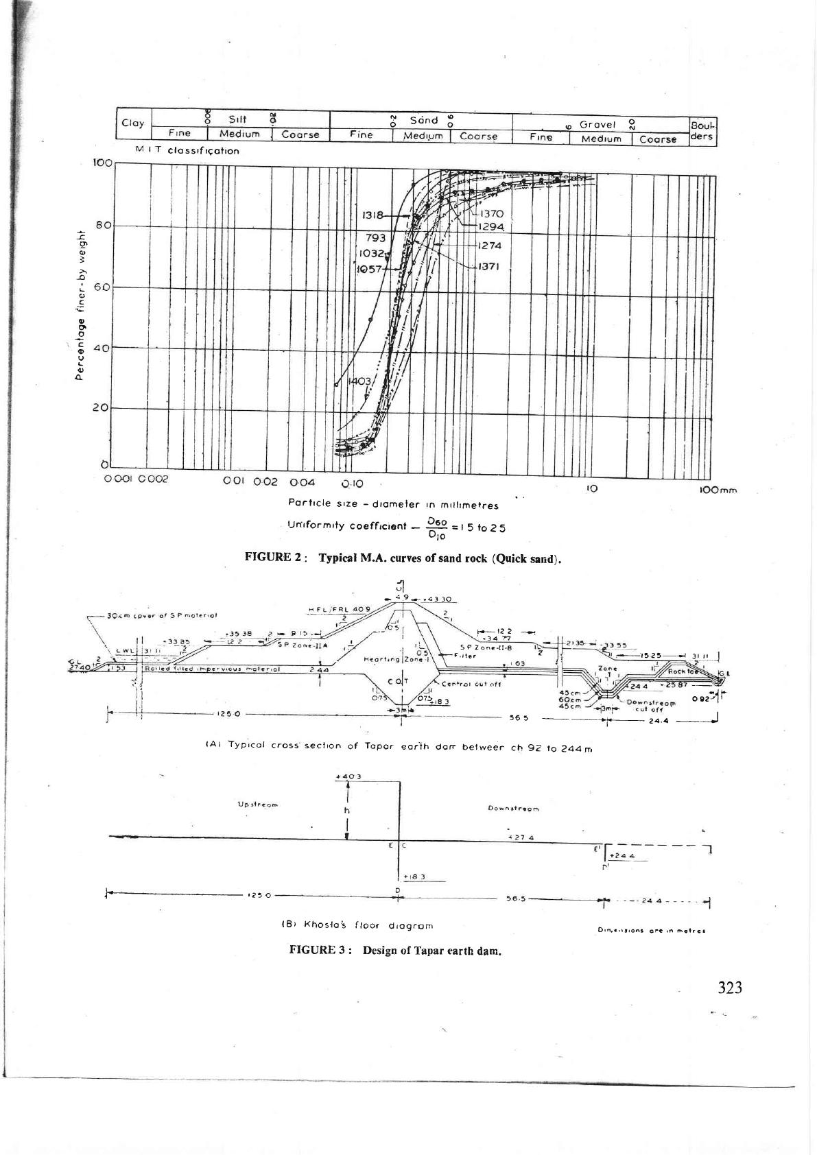
These details
are
shown
in
Figure
3.
(i)
Provision-of
upstream impervious
bla,nket
to
increase
length of seepage flow
and
thereby
reduce
uplift
pressure
as
well
as
quantity
of
seepage.
322
(ii)
Provision
of
loading
berms on
upstream
and
downstream
to increase
stability
lgainst
high
seismic
forces
recommended
(0.15
g).
(ili)
Provision
of
additional
toe cutoff
on
dou,n-
stream
to
control
exit
gradient
at
toe.
of
dam
and
thereby prevent
piping.
(iv)
Provision
of inverted
horizontal
filter
between
central
cutoff
and
toe
cutoff
to reduce uplift
pressures
in
this
reach.
(u)
Provision
of
relief wells
to reduce
excessive
hydrostatic
pressures
on dor,vnstream
and
thereby
reduce
the
possible
piping
action.
3.1
The
Khosla'.s
theory
of
"Design
of
Weirs
on
Permeable Foundations"
was
used
to
hnd
out the
irres-
sure distribution below
the
floor
and
the exit
gradient.
It
is eonsidered
that
the
impervious
blanket, central
cutoff
and
inverted
horizontal
filter
form
an
imper-
vious
apron
corresponding
to
rigid
concrete
floor
assumed in
Khosla' s
theory.
The
central cutoff and
the toe cutoff are
treated
as
sheet
piles.
The
floor
diagram
is
given
in
Figure
3
(b).
3
sond
3
e
Grovel
R
c
lo
ssrf rCotron
(tt
q)
3
I
t_
q)
c
o
(t
o
,c
o
I
o
u
Porlrcle
srze
-
dromeler
rn
mrtlrrnerres
lnrformrty
coeffrcient
-
P
=t5
to25
oro
FIGURB
2
:
Typical M.A.
curves
of
sand
rock
(Quick
sand).
n
ul
-.:,9*,a330
tr
li
2
---o.r
.34
'o75t$
3
(A
) Typrcof
cross
sectron
of
Topor
eorih
dorr
belweer
-F-t5?5_,ei
3_l
[_J
36
5
r_
24.4
ch
9?
to
?44 n,
')ts
o
92/ll
J
#r?5o
lBt
Khos'lo's
floor
diogrsm
FIGURE
3
: Design
of Tapar earth
dam.
J/.J
5
P
2
one-lI-8
F,ltri
Z
Drn a,r!ton3
oFG
rn
6alrca

bt:125
m
191.5
1
:
tff
:19'8
125
-
tffi-
:
o'687
:
l-0.687
:0.313
From
Plate
VII-6 of
the C.B.I.P. Publication
No.
6E:100-59.5:40.5o/o
6D:38%
6
C
:
34.5%
For
downstream
pile,
d
:
27.4-24.4
-
3.0
m
+:+:
,r#
:
0.0165
*E':
10%
iD':8%
Exit
gradient
at downstream
end
of toe
cutoff.
3.1.1
The
pressures
at
E,D,C,E'and
D'
are
computed
as
under:
For
Central
Pile
:
d:27.4-18.3
:
9.1 m
b:125
+
56.5
:
181.5
m
(27.4
-
24.1,
*
Wt.
of
overburden
of
density
1.6
gm/cc
of
3.6 m
(31.0
-
27.4)
Equivalent
Height
of Water
:
3.0
x
(2.0
-
1.0)
x
3.6
(1.6)
:3.0+5.8
\
:8.8m
The
factor
of
safety
against
uprift
at
toe cutoff
8.8
:
lfr
8.27,
a
safe
figure.
(1)
To
extend
blanket
on
two flanks
so
as
to con-
nect
to impervious
clay
layers
occurring
at
lgwer
elevations.
(2)
To
extend
blanket
at
the
same
elevation with
radius
equal
to
length
of
blanket
on
both
the
flanks,
so
that
the
effective
blanket
length
is
same
even
for
seepage
from
flanks.
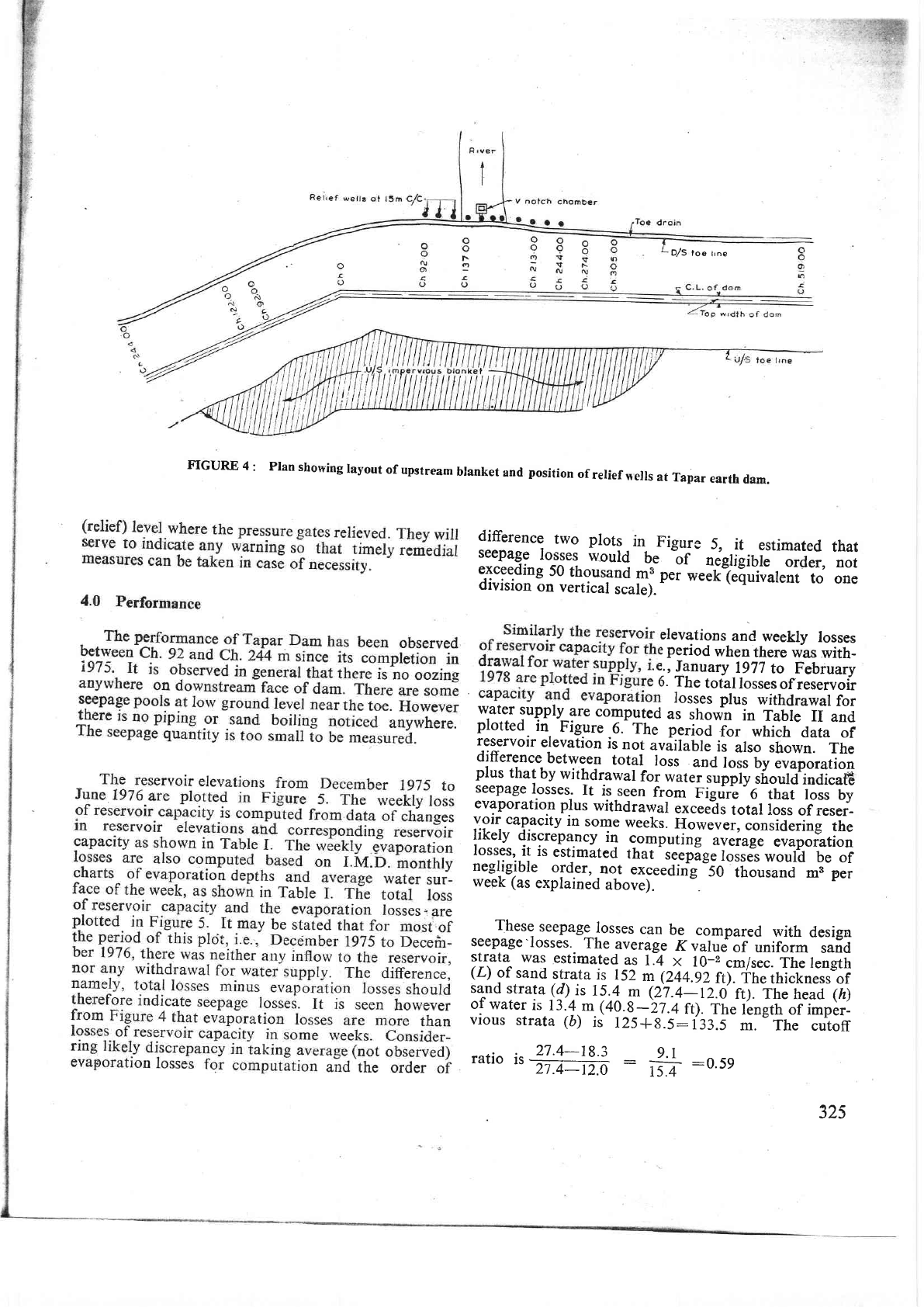
The second
alternative
was
economical
and
easier
to
constiuct.
ft
was,
therefore,
adopted
as shown in
Figure 4.
3.2
The horizontal
filter
has
been
provided
in three
layers of
45 cm,
60
cm
and 45
cm
thickness
as
shown
in Figure
3. The
coarseness
of filter
increased
from
l^gwer
!o
ynRer
layer.
By
providing
this
type
of
inverted
filter, it
has been
ensured
that
foundaiibn
sand will
not be able
to
T.ov-e
up
but excessive
hydrostatic pres-
ssure will
get
dissipated.
The
size
of ihe
each filter
lg-y.t has
been decided
from
the
following
coventional
filter criteria
:
t)
1'u
<4to5
Qae
n
#
:4to2}
93L5
+
<2s
dso
Where'D'denotes
filter
material
and.,d'
denotes
base
-material
3.3 Relief
wells
(10
m
deep)
at
15
m
centre
to cenrre
were
recommen_ded
in
the gorge
portion
between
Ch.92
m
and
Ch.
244
m to
bi tJcateO
at
a distance of
7
m
from
centre
line
of
the
toe
drain.
The relief
wells
which
are constructed
with
15
cm
diameter
slotted
pipe
surrounded
by
grqde
d
filter
permit
the ingress
of seepage
water
into
the
well
and
allow
it
to rise
to the outfall
b
7
lL
b
r
-jL
-b
t2
where,
Ge:#"
-+E
I
_-
3.83
3.1.2
This
is
higher than
the
permissible
value
of
U6
for medium
sand.
The
reliance
is, however, placed
on
inverted.filter
of 24.4 m
(80
ft) length
downstream
of toe
cutoff
and the
load
of the
earthen
erdbankment
above
the
toe
cutoff.
3.1.3
The residual
pressure
at
the
bottom
of
the
toe
cutoff
is
S
D'
:
8o/o, i.e.,0.08
x
13.4
:
1.97
m of
water.
The
downward
pressure
p'
-
Submerged
weight
of
sand
of
density
2.0
gmlcc
of
3
m.
324
D/S
toe
trne
FTGURE
4
: PIan
showing
layout
of
upstream
btanket
and
position
of
rerief
nells
at
Tapar
earth
dam.
difference
two plots
in
Figure
5,
it
estimated
that
seepage
losses
would
be
"of
negligibie--
orA.r,
not
:T:::lTs
r0
thous3nd
mB
p.i
*..r?Eui*r.ii'
to
one
olvlsron
on
vertical
scale).
-
elevations
and
weekly
losses
::i;f,f#;illlT
E:rilT$
i. The
totallosses
of
reservoir
Iosses
plus
withdrawal
for
w,at:r
supply_are
computed
as
showh
io
raUre
II
and
plotteo.
ln.
t,lg.ure.6.
The
period
for which
data
of
reservoir
elevation
is
not
auiilatti
ii-arso-snown.
The
difference
between
totar
toss
analoss
b/;;;p"ration
plus
that
by
withdrawal
for
water
supply
snoud'indica6
seepage
losses.
It
is
seen
from
Figfr;-"6-th"t
ross
by
evaporatio.n
R]us
withdrawal
excee'ds
total loss
of reser-
#11.:ip,T1tlT
some
weeks.
However,
considering
the
lt^l:tl^
gyf.pl"cy.
il
computing
average
evapoiition
losses'
rt
rs
estrmated
that
seepa-qe
losses
would
be
of
negligible
order,
not
exceeaing
5O
thousand
m;-p;;
week (as
explained
above).
These
seepage
losses
can
be
compared
with
design
seepage-losses.
The
average
Kvaludof
uniform
sand
strata
was
estimated
as
t.q
x
r0-2
cm/sec.
The rengh
(z)
gf
sand
srrata
is
152
m
(244.92
rt)-fne
thictness
of
:?i9
*_!tuta (d).is
1j..1
y
e7.4-rz.ci
rt1. rrrc
r,.uo
faj
oI
water
is 13.4.m-(40.s
-27.4
ft).
The
I'ength of impir-
vious
strata
(b)
is
r2s+s.5:r33.5
m. The
cutoff
_^.:^ :_
27.4_19.3
g.l
ratro
rs
-76-12.0
:
,,-=?
:o'59
325
E
c
o
.P
L
6
o
14
o
g
L)
L
n
()
o
o
o
L'
L
o
L
o
6
g
o
6
$
o
363
36
35
400
350
300
250
200
t50
too
5-o
o
I
I
Tolol loss
Loss
by
evoporof
ron
Inflow
1-t
-_\__----__-
Fef
76
Mor76
Fer-rod
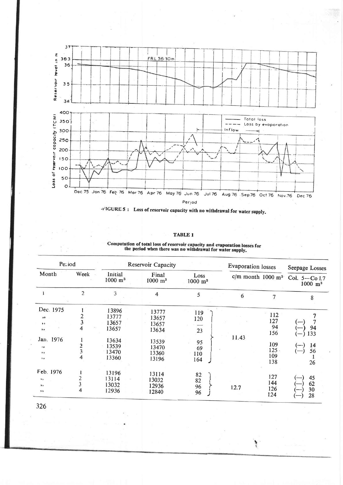
't"lGURE
5
: Loss
of
reseryoir
capacity
with
no
withdrawal
for
water
supply.
TABLE
I
Conlputation
of total
loss
of reservoir
capacity
and
eyaporation
lossrls
for
the
period
when there
was no
withfuawal
for
witer
rutply.
--- --
Fe:iod
Reservoir
Capacity
@.r
Seepage
Losses
c/m
month
100;;8
Crtj-C."
t-?
1000
m3
Month Week
lnitial
1000
mg
Final
1000
m3
Loss
1000
mB
Dec.
1975
t,
,,
,,
Jarr.
1976
),
,t
tt
Feb,
1976
tt
tt
)t
t 38e6
13717
r3657
13657
13634
l
3539
t3470
I3360
r3196
r3lt4
r3032
12936
13777
13657
t3657
13634
13539
t3470
r3360
13196
13114
r3032
r2936
12840
I1.43
r2.7
(-)
14
(-)
s6
I
26
(-)
45
(-)
62
(-)
30
(-)
28
7
7
94
133
I
2
3
4
I
2
a
1
4
F
I
I
I
I
)
I
t'
I
)
l19
120
23
95
69
il0
r64
82
82
96
96
112
127
94
r56
109
125
.
109
138
127
t44
126
r24
(-)
(-)
(-)
I
2
3
4
326
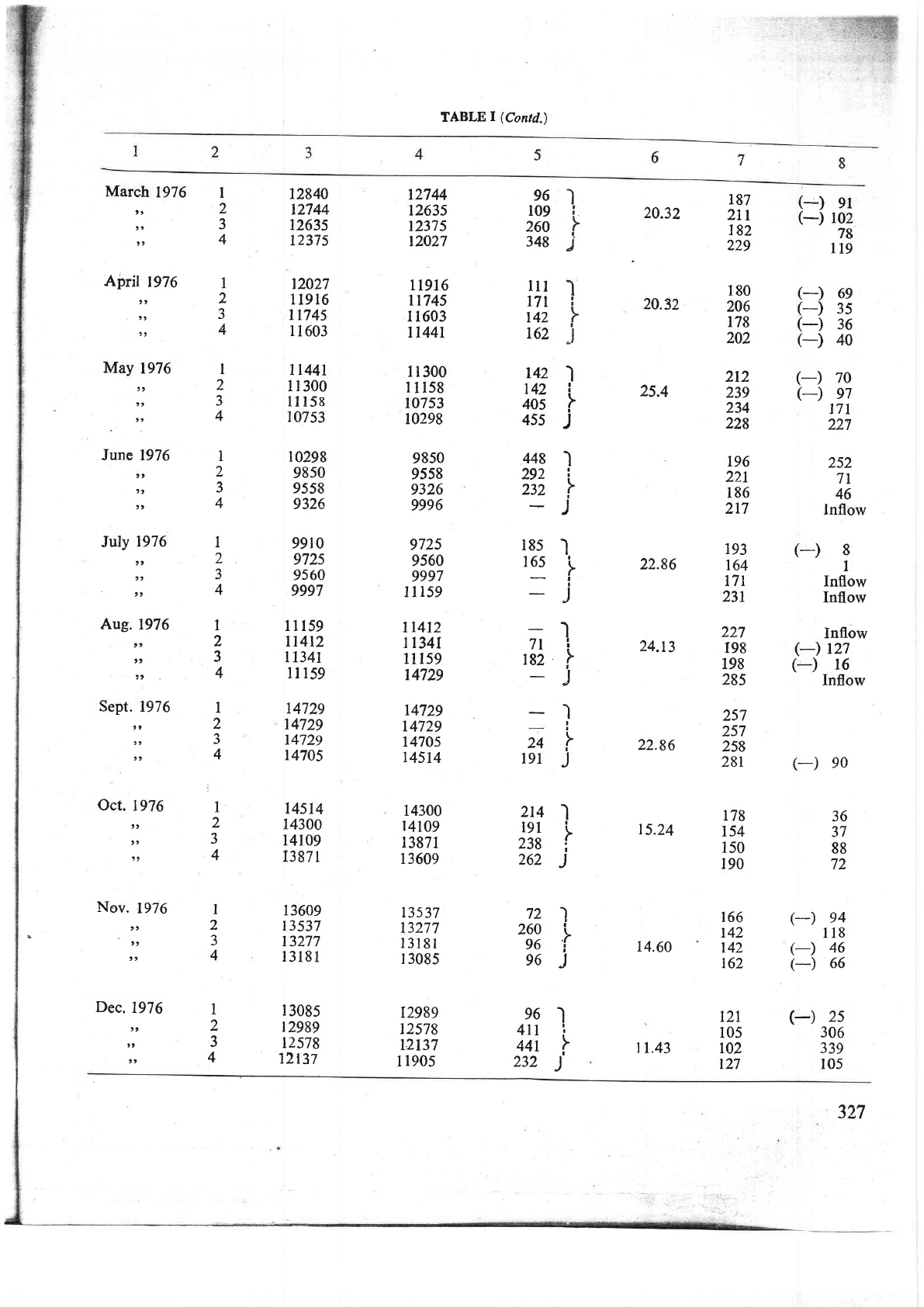
TABLE
|
(Contd.)
March
1976
,,
)t
))
April
1976
t,
,,
t,
May
1976
t)
),
,,
June 1976
,,
,,
,,
Trrlv 1976
),
,,
-
,t
Aug.
1976
,,
,,
)t
Sept.
1976
t)
t,
),
Qct.
1976
t,
,,
),
Nov.
1976
),
,t
,,
Dec.
1976
,,
tt
,,
72840
12744
1263s
12375
t2027
119r6
1t745
u 603
1t44r
il 300
11 158
107
53
10298
9850
9558
9326
9910
972s
9560
9997
lll59
lr412
I l34l
ll 159
14729
14729
14729
r4705
14514
r4300
r4109
I387
r
13609
13537
13277
r318t
l
3085
t2989
t2578
12137
r2744
t263s
1237s
r2027
11916
rr745
I r603
tl44r
11300
lll58
t0753
10298
9850
9558
9326
9996
9725
9560
9997
rr159
11412
tr34I
1l t59
14729
r4729
14729
t470s
r4514
14300
14t09
13871
l 3609
t3537
13277
13181
I 3085
12989
12578
t2137
I
1905
I
f
I
)
I
I
F
j
I
I
F
)
I
I
J
t
2
3
4
I
2
J
1
I
2
3
4
I
I
I
I
I
J
I
I
I
J
l
t
I
I
)
I
I
I
)
72
260
96
96
I
2
3
4
I
2
J
4
I
2
J
4
I
2
a
J
4
I
2
J
4
96
109
260
348
lu
171
142
r62
t42
r42
405
455
448
292
232
20.32
20.32
25.4
22.86
24.13
22.86
15.24
14.60
t1.43
187
2ir
182
229
180
206
178
202
212
239
234
228
196
221
186
217
193
r64
t7l
231
227
I98
198
285
257
257
258
28r
178
t54
150
190
r66
r42
t42
t62
t2r
r05
r02
r27
(-)
9l
(-)
102
78
n9
(-)
6e
(-)
3s
(-)
36
(-)
40
(-)
7o
(-)
e1
171
227
252
7l
46
lnflow
I
2
3
4
I
2
J
4
l8s
I
165
i
)
I
7ri
r82
r
)
(')
8
I
Inflow
Inflow
Inflow
(-)
r27
(-)
16
Inflow
(-)
ec
36
37
88
72
(-)
e4
118
(-)
46
(-) 66
(-)
2s
306
339
105
24
19r
2t4
191
238
262
96
4rr
441
232
327
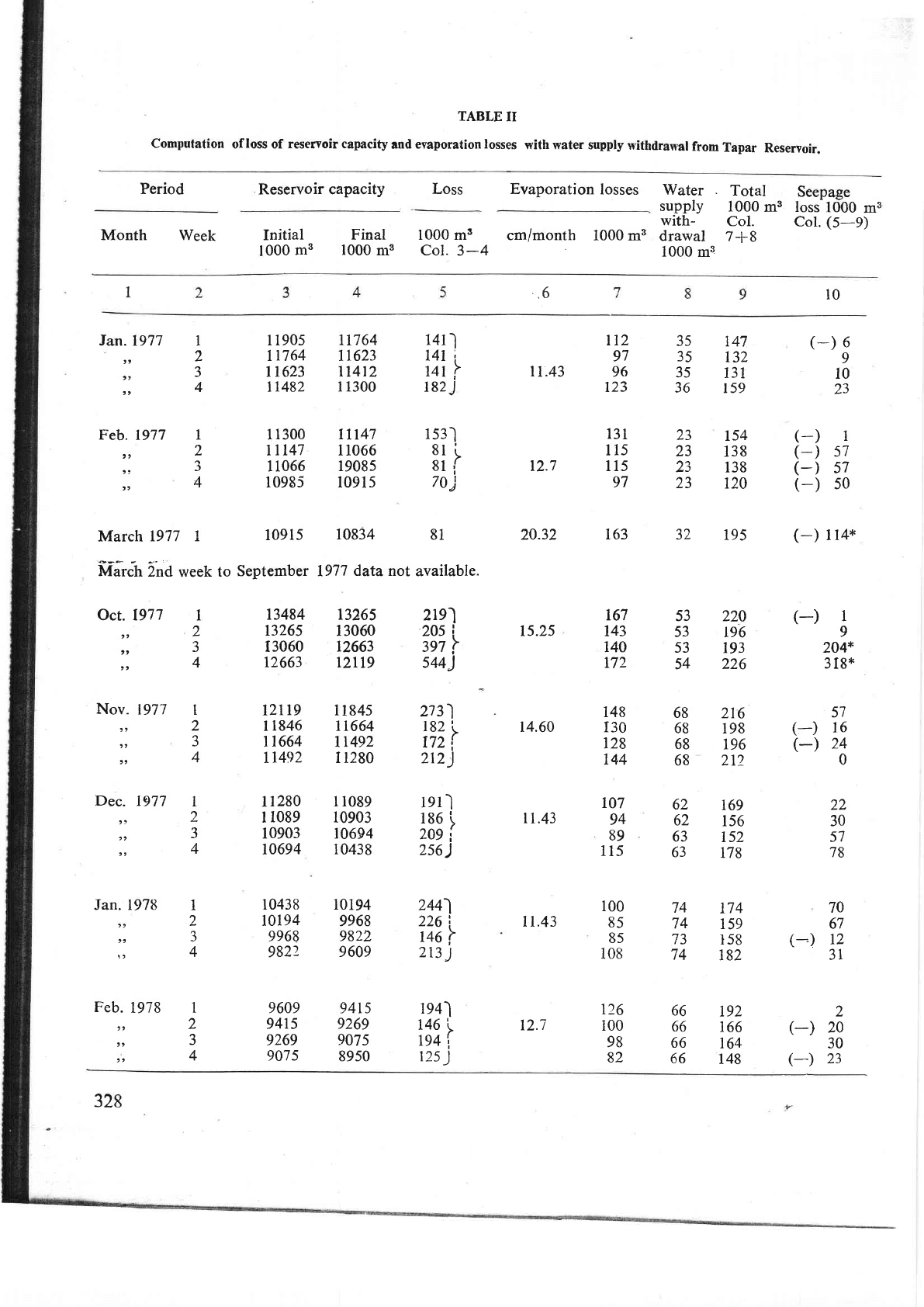
TABLE
II
Computation
of
loss
of
reservoir capacity
and
evaporation
losses
with water supply
withdrawal
from
Tapar
Reservoir.
Period
Month Week
Initial
Final
1000
ms 1000
mg
1000 m3
cm/month 1000
m3
Col.3-4
Reservoir
capacity
Loss Evaporation
losses
Water
Total
supply
1000
m3
with-
Col.
drawal
7
+
8
1000
ma
Seepage
loss
1000
m3
Col.
(5-e)
10
,6
Ian.1971
tt
t,
t,
Feb. 1977
t)
);
t,
March 1977
I
[,iat"-tt
ind
week
to
Oct. 1977
),
,,
,t
Nov.
1977
)t
),
,,
Dec.
1977
'J
)t
tt
Jan. 1978
)t
tt
))
Feb.
1978
))
,,
tr
13484
r3265
I3060
12663
tzr19
11846
rt664
11492
Ir280
I
1089
r0903
10694
10438
t0194
9968
9822
9609
94r5
9269
907 5
13265
13060
12663
r2t19
11845
1r664
1r492
I 1280
l 1089
10903
10694
10438
r0194
9968
9822
9609
9415
9269
9075
8950
2re)
20s
i
3e7
r
s44J
2t
3)
r82
,!
r72
i
2r2
)
lel
I
196
'\
20s
i
2s6
)
244)
226
i
ru6r
2r3
)
1e4l
146
,
194'l
12s
)
lt.43
12.7
20.32
15.25
r4.60
l
1.43
11.43
12.7
(-)
6
9
10
23
(-)
(-)
(-)
(-)
(-)
t ta*
(-)
1
9
204*
3
Ig*
57
(
)
l5
(-)
24
0
22
30
57
78
70
67
(--)
12
31
(-)
(-)
1
2
a
J
4
1
2
J
4
l 190s
11764
t1623
t1482
1
1300
tll47
1 1066
10985
11764
1r623
tt4t2
I 1300
ttr47
11066
1908s
10915
1411
l4l
t
urr
182
J
r
s3l
8t
i
81
i
70)
r12
97
96
123
131
ll5
115
97
163
t67
143
140
172
148
I30
t28
144
r07
94
89
115
100
85
85
108
r26
100
98
82
35
35
35
36
23
23
23
JZ
53
53
53
54
68
68
68
68
62
62
63
63
74
74
73
74
66
66
66
66
147
t32
131
159
154
138
138
r20
195
220
r96
193
226
216
198
196
212
169
156
152
178
174
159
l5B
182
192
r66
164
148
1
57
57
50
10915
10834
81
September
1977
data not
available.
I
2
t
J
4
I
2
a
J
4
t
2
J
4
I
2
a
J
4
2
20
30
23
1
2
J
4
328
17
trH. l
lm
3a
400
350
300
250
200
r5G
roO
I
sot
€
c
q)
q)
o
q)
o
U
I
I
o
o
D
u
L
o
0)
o,
L
o
o
-)
363
36
,,on77
Feb77
Mor77
Apr77
Moy77',"
Nov77.
Dec77
Jon
78
Feb78
perrod
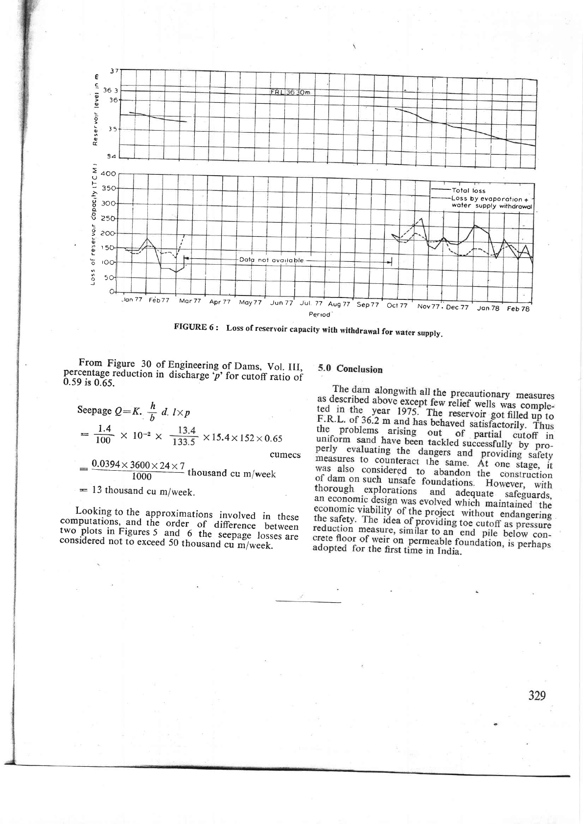
FIGURE
6
:
Loss
of reservoir
capacity
with
withdrawar
for
Eater
supply.
From
Figure
30
percentage
reduction
0.59
is
0.65.
Seepage
Q:K.
of
Engineering
of Dams,
Vol.
III,
in
discharge'p'for
cutoff
ratio
of
d.
Ixp
cumecs
0.0394x
3q@4x7
1000
thousand
cu
miweek
h
b
-*#xro-2x
xl5.4x
t52x
0.65
-
13
thousand
cu
m/week.
Looking
to
the.
approximations
involved
in
these
compurations,
and
rhe
order
of
ditr
;;n;;
u"r*."r,
two
plors.
in
Figures
5
and
6
irr.
l..pug.-
f
ol..s
are
considered
not
to
exceed
50
thousand
cu
"r1,,r..t.
-Totol
loss
Loss
by evoporotron
+
woier
supply
withdrowol
Doto noi
ovorlo
