Indian National Committee on Large Dams. Design and Construction Features of Selected Dams in India
Подождите немного. Документ загружается.

Dool
and
providing
a
cut-off
through
this
sand. This
was
agreed in
principal.
This
could
be achieved
in
number
of
ways.
The
choice,
would
however,
depend
upon
the factors
like
the overall
construction
scheiule,
econoTy and
what
is
more
important,
the method
of
river
diversion.
During
the
dlversion year,
the sand
platform
had
to
be
prepared
at
the base
of
the
dam,
a
suitable
temporary
cut-off
provided
below
the diver-
sion dam which
again
wai
to
be
raised
to
a height
of
32
m
all in
one
season
of
200
working
days. ftre
time
available
for
each
operation
was
ihus strictly
limited.
The
method
of
providing
suitable
temporary
cut-off
for
the
diversion-
dam
hAd,
therefore,-
to
b-e
quick
ald
reliable.
Driving
sheet piles
could
have
been
an obvious
choice,
but
for
the numerous
boulders
in
the
foundation.
Grouting
would
be
a lengthy and
time
consuming process
and
hence
was not
suitable
apart from
the
economics.
Provision
of 0.6
m thick
continuous
concrete
diaphragm
to
serve
as
a
temporary
cut-off
for the
diversion
dam
was,
therefore,
adopteb
as
it could
be
constructed
very
expeditiously
with a
trenching
machine
using
the
rev-erse
mud circula-
tion^process.
This
is discussed
separately
in
paras
13
to 13.5.
The
alternatives
open
for
provi-Oing
a
perma-
nent
cut-off
in
the
river were
:
(t)
Tq
rely_upo.n
the
temporary
concrete
diaphragm
below
the
diversion
dam
and
accept it
ai a
per-
manent
cut-off.
(ii)
To
provide
a
grout
curtain
rvith
suitable
grouts
lik_e
clay-chemical
and
chemical
just
up_
stream
of
the
diversion
dam.
(1ff)
As
an
alternative
to
(fi)
to
construct
a
second
line
of
the
concrete
diaphragm
some
distance
upstream
by way
of
providing
a
further
safety
factor.
(fv)
To
grout
the
sancl
in
between
the
above
men-
tioned
two
lines
of
concrete
diaphragms
with
suitable grouts.
(v)
As
an
alternative
to
(fr,)
to
provide
a
positive
.
earthlill
cut-off
down
to
rotk
betrvein
the
two
diaphragms.
The
alternatives
of
a
single
or
double
line of
con-
crete
diaphra_ems,
i.e.,
alternatives
(f)
and
(iii),
w€r€
not considered
as
such
diaphragms
could
not'bs
relied
rpon
to
provide
a
permanent
cut-off.
The
choice
was
thus
left
between
ahernatives
(tv)
a'd
i'j.
After
examlning
the
econornics,
the
avaiiauiriiv
or matdriats,
convenience
of
execution,
the
time
factor,
etc-, it
was
fin-ally
decided
to
go
in
for
the
alternative
1r,;'of
pro_
yidjng
the
conventional
type
of
earthfill
trencir
cut-off
in
between
the
two
diapliragms.
.
According
to
the
construction
schedure,
the
diver-
sion
dam with
one
diaphragm
underneaih
*u.
cons-
tructed
in
the
year
of
-rivei
diversion.
The
seconcl
diaphragm
or! the
upstream
side
was
also
casr
in
the
same_
yea{.
The
cut-off
trench
in-between
was
exca-
vated
and
backfilled
in
the
succeeding
y"ui-
ll.4 Cut-of
o,
the
Right
Bqnk
Terrace
12.
Diversion
Channel
l?.2
Sevelal
alterna.tive
{ignmenrs
with varying
radii
of curvature
were
tried.
Fiiallv
a radius
of
turvature
of
541
m was
adopted
as
a
reasonable
balance
bet-
wggl
economy
and
hydraulic
performance.
The
bed
width
was
adopted
as 235
m. The
ratio
of
radius
to
bed
width
comes
to
only
2.3
against
5
recommended
conventionally.
The
length
of
diversion
channer
with
this radius
was
1372
m.
The
excavated
soil from diver-
sion
channel
was
proposed
to
be used for earth
dam.
26e
12.3
Fair
Weather
Channel
and
Construction
Sluices
upsrream
end
El.
4,3.29
m
ar
on
completion
of
the
work
tength
of
spillway
body
an,
was
grouted
by
a
pipe
iyste
r2'4
Design
of^protective
works
connected
with
the
Diversiori
Channei,
-
"
The
diversion
channer
at
Ukai,
because
of
its
sharp
curvature
was
subjected
ro
int.ni;ue
-rlvo-:tynamic
action
and
therefore
--int.iriur
moder
studies
were
carried
out'
The
our.i"uiil"r
of
model
studies
are
enumerated
belorv
:
(a)
Flood
waters
were
likely
to
cause
a
short
circuit
fl,ow
pararier
tothe
uii,
"i
n.i.
dam
and
spiltway,
and
offi*;""rh;
,ii,u.rrion
channet
and
ihe
.uioniy
da;--fo;;ludonr.
(b)
Because
of
the
convex
flor,v,
very
high
velo_
cities
were
noticed
at
some
critical
loca-
tions.
,""I*.[Tlorving
protective
rvorks
were,
therefore,
posed
to
cater
to
velocities
between
7.6
to
I I
m/sec.
12.5
Construction
of
Diversion
Cltannel
The
work
of-excavation
of
diversion
channel
was
started
in
196,4,
partlt-r.itt
Oepa,-'-'.
v.rs'r
and partly
wittr
contractor.
The
can
be
seen
in
photo
i.
fn"
toti
]vas
3.16
M
cu_
m
in
ou.rUurt.o
e
in
l9ck.
The
flood,
-
oi
'A;il,
te
problems
of
silt
removal
frJm'
Aiue
fair
rveather
channel.
ifr.^"si"eriat
I
spared
for
repairs
and
restoration
ol
tion rvorks
in
the
fl""A
-"#..irj
ur.u,
the
excavation
lot
f;ir-;;;;h'er
ch;
c.ompleted
and
fair
rv.utt
.r'no*
o
diverted
on
g
Feb.r..v^rg6-d.
e
pip.
culvert
and
two
bridges
rvere
provided-
f.i
ir"m"
The
totar
excavarion
of
diveT:iol
ctrannel
incruding
desilting
and
ut'isation
ol-s;;i-i"
various
reaches
of
earth
dam
is
as
under
:
Particulars
Total.
quantiry
utilised
inMcum
Earth
dam
between
hill
Nos.
land2
Gorge
dam
Right
bank
earth
dam
Stripping
quantity
and
Compulsory
bunds
1.869
0.85
r.274
1.34
0.34
waste
pile
Total
quantity
5.673
(i)
Earthen
embankment,
i.e.,
_quide
bund
on
up_
stream
of
,
dam
arignment
between
river
and
diversionchannel.
e----
(tt)
4
spur just
ar
the
enrry
of
the
diversion
channel
on
right
bank
to
a..fl".t
tir'.
nolO
away
from
,!.
upstream
right
bank.
The
location
was
decided
by
the
hyd"raulic
moOei,,"uOi.r.
(tft)
A
special
tyle
of
caged
pitching
all
along
th"
upsrream
{ght
bank
to
iater
to-
the
velocities
of
about
5.-0
m/sec
.u.n
after
construction
of
spur.
270
12.6
Construction
of
Spur
.
According
to
the
final
rarsed
to
El.
92.30
m,
i.e.,
overburden
excavation
;;
done
in
three
months
.u.f.
spur was
hardly
3
to
4
mon
wgr.k
had
to
be
converted
r
,u"-
. "-,l.
'tttnt'
i
litt
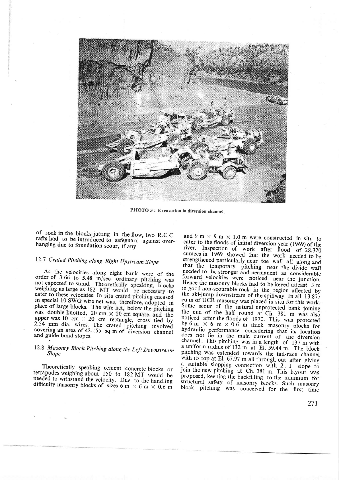
PHOTO
3
: Excavation
in
diversion
channel.
of
rock
in
the
b]ocks
jutting
in
rhe
flow,
two
R.C.C.
rafts
had
to
be
introdirced
io
tur.go"id
Lg"i"rt
over-
hanging
due
to
foundation
scour,
i?;t:
12.7
Crated
pitching
along
Right
Upstream
Slope
As
the
velocities
along
right
bank
were
of
the
order
of
3.66
to
5.4g ml,
not
expected
to stand.
The
weighing
as large
as lg2
Iv
cater
to
these
velocities.
In
in
special
l0
SWG
wire
net
place
of
large
blocks.
The
was
double
knotted,
20
cr
upper
was
10
cm x
20
cm
rectangle,
cross
tied
by
2.54
mm
dia.
wires.
The
crated
iii.t
i"g
involved
covering-
an
area
of
42,155
sq
m
of
'di";;;i30
'"nunr,.t
and
guide
bund
slopes.
12.8
Masonry
Block
pitching
along
the
Left
Downstream
Slope
. .
Theoretically
-
speaking
cement
concrete
brocks
or
tetrlng{es
weighing
abouf
150
to
rg2
Mr
would
be
needed
to
withstand,
the
velocity.
Due
to
the
handling
difficulty
masonry
blocks
of siies
6
m
x
6-;
*-
O.O
*
and9m
x
9m
x
l.Om
were
constructed
in
situ
to
carer
ro
the
floods
of
initial
diversion y.u, (
rc-ogl"i
trri
lver
Inspection
of
work
artei-
frooa'^-it
zs,sza
cumecs
in
1969
showed
that
the
work
neJeo
to
be
:ll._"g.i!.ned
particularly.
near
toe
wall
all
along
and
rnar.
rhe
temporary
pitching
near
the
divide-warl
leeded
to
be
stronger
and
perhanent
as
considerabre
forward
velocities
were
nbticed
olui-
tt
J^'iun"tion.
Hence
the
masonry
brocks
had
to
u.
t.v.d-"trJirt
3
rn
in
good
non-scourable
rock
i;
rh;_I;;l;"
unlit.a
by
the
ski-j_urnp
downstream
of
the
spitiwiy-.
il;if
r3,g77
cu
m
of
ucR
masonry
was praced
in
siiir
f;
;hlt
work.
Some
scour
of
the. ^natural
unprotected
banli
:oinm!
the
end
of
the
harf
round
ut'ctr.
-:sl
-ri^'ii,
utsu
noticed
after
the
floods
of
1970.
irrit-*ur'
p.Lrected
-by9ot
x
6
m
x
0.6
m
thick
masonry
biocks
for
hydraulic
performance
considering
-th"i
it-s--llcation
ooes
not
lie
in
the
main
currenf
of
the
diversion
channel.
This.pitching
was
in
a rergth
oi-r37
m
with
a unrt'orm
radius
of r32
m
at
El.
59.44
m.
The
brock
pitching
was
extended
towards
the
tail-ra"i--channel
with
its.top
at EI.
67.97
m
a[
through
out
;Gr-
giui'e
1,1uj1able
slo.pping
connection
wlth
2:
1
-
,lop.
to
lorn
the
pew
pitching
ar
Ch.
3gl
m.
This
layout
was
proposed_,
kee-ping
the
backfilling
to
the
minimum
for
11.^l:1".11-
p.f.rv
of
masonry
6tocks.
Such
masonry
olocK
pltchlng
was
conceived
for
the first
tim-e
271
for
such
river
training
work
and
it
was
in
the
nature
of
prototype
experimefrt.
13.
Concrete
Diaphragm
ially
necessitated
in
R.B.E.D.
r
,because
of
standing
pool
d
because
other
methods
of
lound
either
expensive
-
oi
Two
concrete
diaphrag'rs
were
constructed
as
underground
seepage
'barrLr
-
to
arrest
the
rarge
inflows
from
the-
'said
ano--ianoy
strata
to
enabre
the
aonstruction
of
conventionar
earthfiil
cut-off.
The
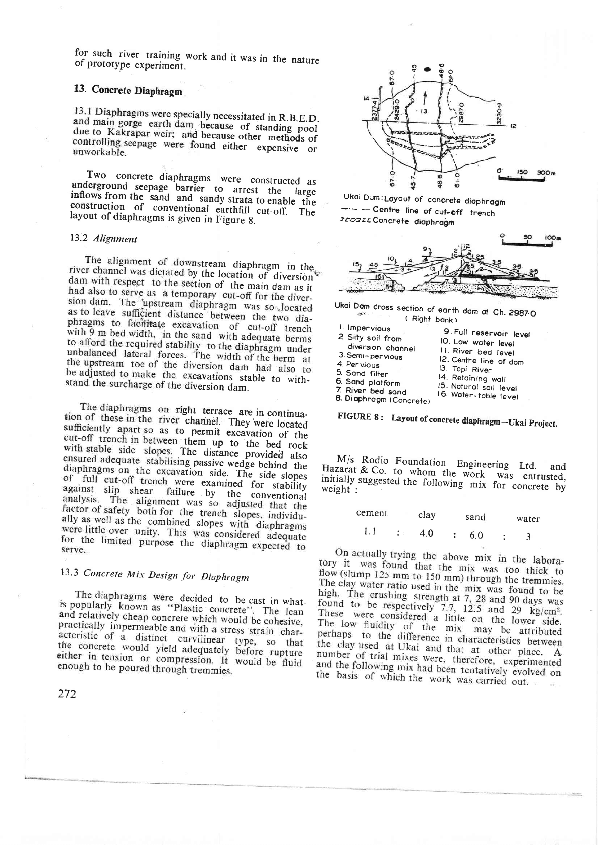
layout
of
diaphrasms
is
giuen-i;
Fid;;b.--'
-'
13.2
Alignment
nstream
diaphragnr
in
the
y
the
location
of
div.rsi;;c,
:tion
of
the
main
dam
as
it
cavatlons
stable
to
with-
version
dam.
ght
terrace
are
in
continua.
channe.l.
They,
were
focaieO
I permrt
excavation
of
the
them_.up
to
the
bed
,;;[
Ihe
distance
provided
;l;;
lg. passtve
wedge
behind
the
rtion
side-
Tlie
side
slopei
ere
examjned
for
stabiiity
ure
by
the
conventiondl
L3.3
Concrete
Il4ix
Design
for
Diapliragm
lecided
to
be
cast
in what.
272
o^9
Y
'
?e
nrsalf,
.-.--+
v
Ukoi
Dcrn:Loyout
of
concrete
diophrogm
Centre
tine
of
cut-off
trench
z.a?
z
EConcrete
diophrolrh
Ukoi
Dom
iross
section
of
eorth
dom
of
Ch.
2gg7.O
'+:"':
t
Right
bonk
I
l.
lmpervious
e
s,riy
soir
r.om
,3.
I;l
;:il,",ji"1"u",
dir,ersron
chonnel
,
i.
ni"".'ied
tevel
3-Semr-pervrous
12.
Centre
line
of
dom
4. Pervious
5.
Sond
filter
13'
Topi
River
g
s."J
;i;;;.,
lf:
fijillli^S",ll!,",
Z
River
bed
sond
t6.
Woter--'toOte
tevet
I.
Diophrogm
(Concrete)
FIGURE
B:
Layout
of
concrete
diaphragm_Ukai
project.
M/s
Rodio
Foun-dation
Engineering
Ltd.
and
Hazarat
&
Co.
to
-rvhor-irr.'
wbrk
*i,
Titrurt.o,
f::lt'rt,tu-egested
tr'.--iorro;;s
mix
roi-
.oiir.t.
by
cement
clay
sand
water
t.l
:
4.0
:
6.0
:
3
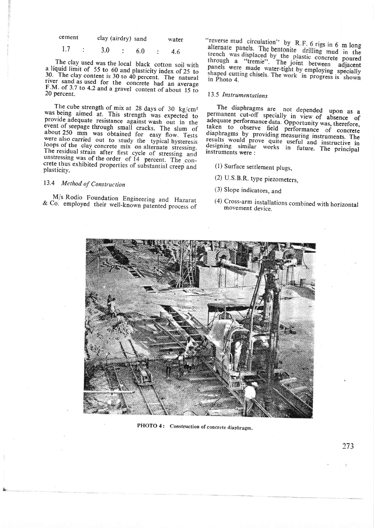
cement
clay (airdry)
sand
1.7
:
3.0
:
6.0
13.5
Instrumentations
The
diaphragms
are
not
depended
upon
as
a
permanent
cut-off
specialry_
in
njr*
oi
uui.n..
of
adequate
performanci
data.
bffort"nity
was,
therefore,
taken
to
observe
.!:ta
fJifor*uo."
of
concrete
diaprragmr
-9y
providing
m'e'asuring
instruments.
The
results
woutd
oiove
quit.
u..rui
?"J"l,irir"?ii""
in
designing
simiiar
,'vorks
in
-
future.
The principal
instruments
were
:
(1)
Surface
settlement
plugs,
(2)
U.S.B.R.
type
piezometers.
(3)
Slope
indicators,
and
(4)
cross-arm
instailations
combined
with
horizontal
movement
device.
rvater
:
4.6
,.Th.r.clay.
used
was
the
local
brack
cotton
soil with
l
liqgid
timit
of
55
to
6_0
and prastlcityl;;;;Lrzs
to
19
The
cJay
content
is
30
to
+b
p.r."rit.
-i-tr-e
-naturat
rrver
sand
as
used
for
the
conirete
had
an
average
F.M.
of
3.7
to
4.2
and
a
gravel
content
of
about
15
to
20
percent.
The
cube
srre_ngth
of
mix
at
2g
days
of 30
kg/cm2
was
being
aimed
at. This
strength
*as
.ip..t.O
to
provide
adequate
_resisrance
uguliri
*uri,
-o,Ii'in
the
eyent.
qf-leepaSe through
s.uli
cracks.
The--
slum
of
about
250
mm
was
obtained
for
"ury
fl;;.
Tests
were
also
carried
out
to
i
--
19-opr
of
the
clay
concrere
The
residual
strain
after
fi
unstressing
was
of
the
order
crete
thus
exhibited
propert
plasticity.
13.4
Method
of
Consttuction
^ I/r
Rodio
Foundation
Engineering
and
Hazarat
&
co'
employed
their
weil-kn6wn
patented
process
of
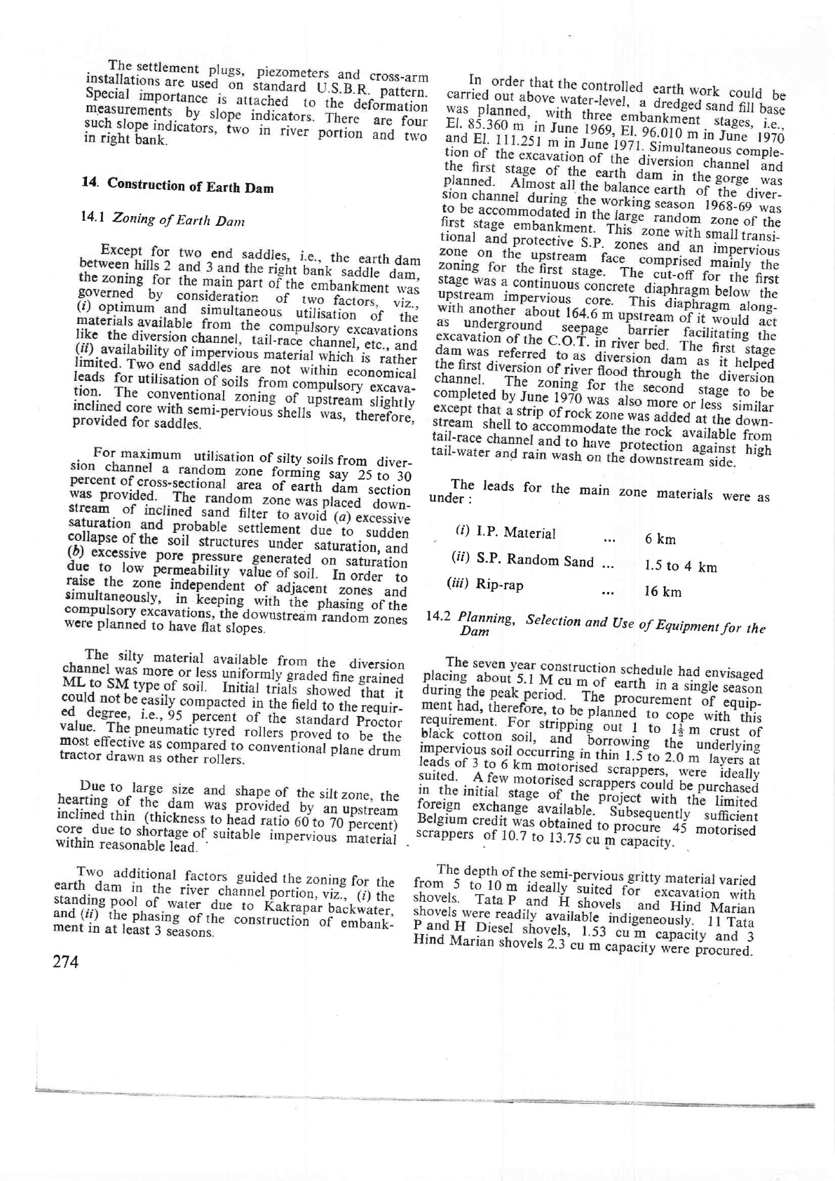
PHOTO
4:
Construction
of
concrete
diaphragm.
273
14.
Construction
of
Earth
Dam
l4.l
Zoning
of
Earth
Dant
rn
of
silty
soils
from
diver-
one
forming
say
25
to
30
rea
oI-earth
dam
section
pes.
274
,"#:
Ieads
for
the
main
zone
materials
were
as
G)
l.P.
Material
6km
(tt)
S.P.
Random
Sand
1.5
to
4
km
(ar)
Rip-rap
16
km
14.2
ffiyinS,
Selection
and
(Jse
of
Equipment
for
the
%
2:tityiiH
Drag-line
attach_ments
were
arso
obtained
for
3
Tata
p
and
H
and
3
Hind
Marian
inouets
foil*"uu"tion
of
the
C.O.T.,
removal
of
silt,
eitraction-of
sand,
etc.
l4'3
construction
programme
of
the
Earth
Dam
in
the
River
Channel
(i)
construcrion
of
rhe
dredged
sandfi[
in
the
dam
seat
to levels
adequatjy
uUou.
ii,
warer
surface
in
the
river.
(tt)
The
compretion
of
the_
downstream
concrete
diaphragT,
rvhich
woutd
u.t
uiii.!'.ut_of
for
the
diversion
dam.
(rii)
Desilting
and
the
excavation
of
the
fair
weather
channel
for
diverting
ifr.^port-mon-
soon
flow
of
the
river.
(iv)
.cgmpletion
of
the
prorecrive
works
and
barance
excavation
oi
trr"-
oiu.rrioi'
"hannel
rvith
simurtaneous
utilisation
"r?r.'"xcavated
materials
in
the
earth
dam,
and
(v)
Raising
the
diversion
dam
and
the
adjoining
porrion
_
of
the
right
bank
i"ii-r,
*iu,
to
El.
85.36
m.
The
programme
for
the
excavation
and
refilling
c
clannel
portion
and
iri
ttr
426
m
on
the
right
bank
embankment
to
elevation
rvas
also
planned
to
be
rc
seat
afrer
refilling
the
C.O.l
lg
season,
the
earth
work
I
to
be
completed.
These
ed
and
slightly
revised
later
enormous
quantity
of
silty
monsoon
seat
in
1969
and
197-0
14.4
Work
done
during
196g_1969
The
flood
of
August
196
silt
in
the
river
UeO
in
t
Due
to
likely quick
consolic
was
filled
without
removine
taken
however
to
r.movj
pockets
by
using
a drag
line
u
deposits
continuously-churning
to
avoid
formation
of a
continuous-
Iayer.
The
"work
;;;
cJmpreted
by 8 February
1969.
The
construction
gf
a
permeable
rubble
barrier
road
across
the
river
for
cr'
banks was
taken
up.
It
\
on
closure
of
the
barrier,
headed
up
to
such
an
.r,
area.
The
construction
of
the
dredged
sand
platform
rvas
planned
so
as
not
to
affect
tlie
overall
!iogr.r,
275
foundations.
fhi,,
hu9
an
added
advantage
of
con_
l?:Xil'T.';;if:t,:l,ll
a"|o'it
*'u
;;r'f,in''iile
down-
The
impervious
earth
br
The
semi-pervious
material
rvas
borrolved
from
the
nearby
hilrocks
*itr.
ilt.
rr.rplr'rnouers
and-
o,i,np.rr.
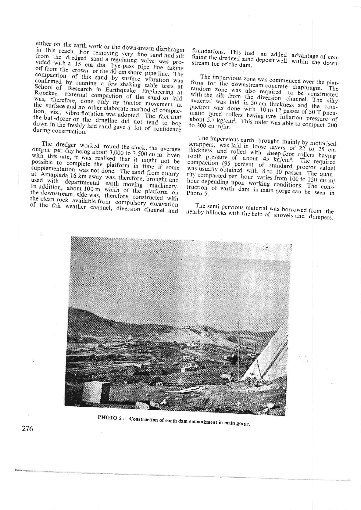
Construction
of
earth
dam
embankment
in
main
gorge.
276
As
the
pneu.matic
tyred
rollers
were
deployed
for
compacting
silt,
the semi-pervious
material
-war
com-
pacted
with
8
to
10 tonne
smooth
drum
rollers.
The
loose
layer
thickness
had
to be kept
15
cm
and
the
required
compaction
could
be obtained
with
l0
to
l2
passes.
The
earth
work (2.7
M
cu m)
for
the diversion
darm
was
completed
by
the
end
of
June 1969. There
was,
however,
no
time
to construct
regular
hand
placed
pitching
-over
the upstream
slope.
A
+S cm dumped
rip-rap
-of
q-uarry
spalls,
etc.,
was,
therefore,
quiitty
laid
with
the help
of rear
dumpers
and
dozers to
protect
the
slope against
rain
cuts
and
.floods.
The
average
daily
output
of
earth
laid
in the
diversion
dam
proper
was
19,820
cu
m/day.
Such
a fast rate
of controlled
earth
work
is
not
usult
in Indian
dams.
With placement
of
earth in
appurtenant
bunds,
erc.,
the rate
of departmental
earth
moving
per
day had
been
about 28,300
cu
m
on
an
average
and
nla
at
times
risen
to
33,980
cu
m
per
day.
For
protection
of
easily
erodible
soils
like
thb
materjals
of
the
random
and iniperviolrs
zones,
about
30
to 45
cm
thick
layers
of
gritty
soil
were
laid
on
the toe
to be
removed
subsequently
with
the
commencement
of
further
work.
While
the
earth
work
for the diversion
dam
yal
1n
progress
the
excavation
and refilling
of the
C.O.T. in
the left
bank
envelope
were
completed.
A_s
grouting
would
be
time consuming,
it was
done
aftgr_
rellling
the C.O.T.
The
main
part
of the
C.O.T.
for the
gorge
dam
was
in
the
river
and was
about
427
m
long.
This
pa,rt
was
proposed
to
be
tackled
during
the working
ceason 1969-70.
But with
the completion
of construction
of
downstream dia-
p,hragm
and
a
pa,rt
of
the upstream
diaphragm,
it was
tlought
prudent
to
tackle
about
132 m
ol the length
of thq
C.O.T.
(where
the rock levels
were higher)-in
the
1968-69
season
itself.
This
would provide
extra
space
for
raising
the earth
dam in
the
commencement
of
the 1969-70
working
season.
Th_e
pumps
and the
booster of
the dredger conti-
nuously
pumped
out
about 50,000 litres per
minute to
lower
the
water-level
in
the
C.O.T. Dumping of
metal
and
murrum
was
continued
for
preparing
the
dam
seat
upstream
of C.O.T.
Two
draglines
and
a
heavy
duty
ripper
with
dozer,
etc., were put
to
work
for
excavation
of
the C.O.T.
down
to
acceptable
rock
level.
All these
machines
made
possible
the
comple-
tion
of about
91.0m
of
the
C.O.f.
The
remaining
length
about
3l
m
could
not
be
tackled
due
to
early
rains.
Advancing
of the schedule
this
way
saved both
time
and money
to
an
appreciable
extent.
Total
earth
moving
done
departmentally
during
the
year
was
about
5.43 M cu
m.
This
was
by
all
means
a
huge work
in
a
single season. The
prin-
cipal
earth
moving
equipment utilised
for
the
purpose
comprised
14 showels
1.9
to
2.3 cu
m
capacity,
45
Ao1olis9{ _sgrappgls
(10.7
to
t?.75_cm);
50
dumpers
10'7
to
13-75
cm;.90
tipping
trucks
e.t
i;
"t"0-tonnes;
and
about
40 bull-dozeri
ano
rracors.
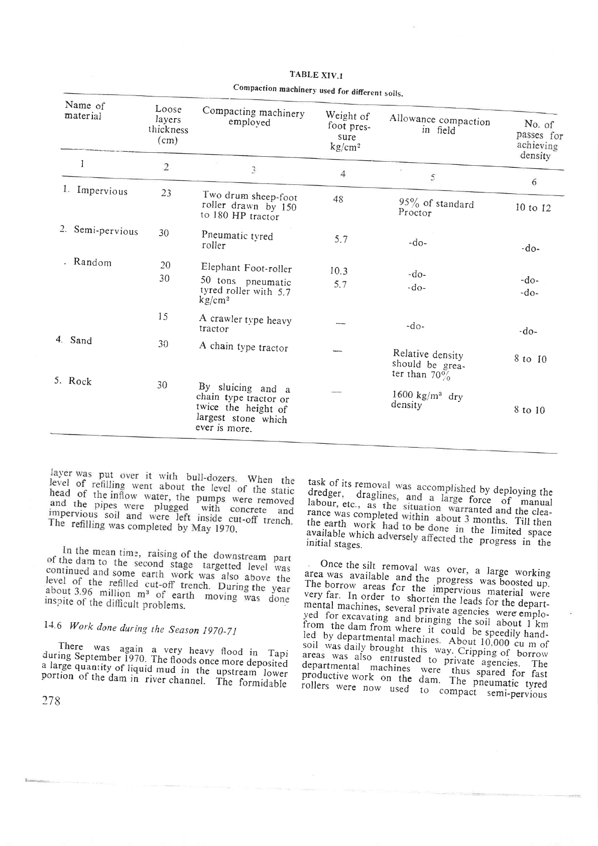
Tabte
xlv.
r
gives
details
of
compaction
machinery
.r.J-rJ,
diffe-
rent
soils.
14.5
Work
done
during
1969-70
,
.This.working
season
also
witnessed
a
heavy
flood
yli.l
depositeq
rrr
th-.
upstream
dam
,.ut,
abour
4,50,000
cu
m
of
low
{elsity
sticky
tiquio-
*,ia
rang-
ing
in
depth
from
6 to
I0
m.-
277
TABLE
xIV.1
Compaction
machinery
used
for
different
soits.
Name
of
materiai
I
Loose
layers
thickness
(cm)
Weight
of
foot
pres-
sure
k_e/cm2
Ailowance
IN
compaction
field
-
Compacting
machinerv
emplo-ved
2.
Semi-pervious
.
Random
Impervious
-r
ZJ
Two
drum
sheep_foor
roller
drarvn
by
150
to
I80
HP
tractor
Pneumatic
tvred
roller
Elephant
Foot-roller
50
tons
pneumatic
t),red
roller
rvirh
5.7
k-e/cm2
A
crawler
t_\'pe
heavy
tractor
A
chain
type
tractor
By.
sluicing
and
a
cnaln
type
tractor
or
twice
the
height
of
rargest
stone
which
ever
rs
more.
30
48
).
/
10.3
)./
95oA
of
standard
Proctor
-do-
-do-
-do-
-do-
Relative
densitv
should
be
-e..i-
ter
than
70o,,o
1600.
kg/m'
dry
oensrty
10
to
12
-do-
-do-
-do-
-do-
8to
I0
8tol0
20
30
4.
Sand
5.
Rock
l5
30
30
tms.
11.6
Work
done
during
the
Season
i970_71
There
was
ag?i!
a very
heavy
flood
in
Tapi
:ri::lq
Seprember-ilz-o
irr.iiSoos
once
more
deposited
:
,119"
quanrity-of
,iquid
rnud
iri-rh;-;;;;;;;";;;;;
porrron
of
the
dam
in
river
chinner.
The
formidable
278
task
of
its
remove
,,#sf::;^J;ifli
[,?:o.fi"n#f!*i
rance
was
comple
anted
and
the
clea_
the
earth
il;li
I
months.
Tiil
then
uuriluUi.
*frr=.fl
u,
the
limited.
space
initial
sta_ses.
e
progress
in
the
-
Once
the
silt
removal
was
area
was
avairabie
-""a
iir.'orlJ;J;,
"*lTf,:#fl?:
The
borro*,
u.:11
f;;1h.
lilieruious
mareriat
were
very
far.
In
order
to
rtroit."'irre
leads
f;;il
d.part_
menral
machines,
-sever3l.
t;i";i;
agencies
*;;;
empro_
yed
for
excavating
ano
uiinging
ihe
soil
about
I
km
from
the
dam
froil,;h;;'it"'.ooto
be
speedily
hand-
l:9, ?.r_g.pqfmenrat
-u.rri".r.''Abou,
ro.ooo
6u
m
of
sorr
ii'as
dail;,
broughr
this
*"y
.b;;;o;;;i
'borroru
areas
was
also
entrusted
to
i
d e
p
a
rt
m
e n
r u
r'
"
"-
u.
r' i;;
- -,'
;;
ulil;j'
ri;iLi
t'f;.
11:
productive
rvork
on
rhe
oan'.
T;;"
ffi;,i';
ryred
rollers
were
now
used
io---.o_pu.t
semi_pervious
