Hillert M. Phase Equilibria, Phase Diagrams and Phase Transformations: Their Thermodynamic Basis
Подождите немного. Документ загружается.

14.3 Quasi-adiabatic phase transformation 305
α
β
α
β
P
P
H
(α+β)
(α/β)
H
(β/α)
H
∆H
m
/C
P
T
e
T
H
m
(a) (b)
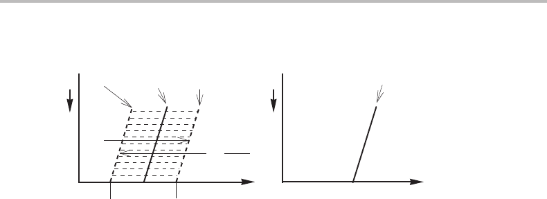
Figure 14.2 Phase diagram for isobaric and adiabatic conditions in a unary system. Notice that
the α and β one-phase fields in the P, T diagram overlap in a region around the equilibrium
temperature.
could form, it would not be stable because it is inside the stable one-phase field for β
according to the T, P diagram in Fig. 14.1.Partofα could thus transform back to β.In
the next section we shall examine a more realistic model.
Exercise 14.1
Estimate the internal entropy production when 1 mole of a pure substance transforms
adiabatically from α to β when the temperature of α is T above the value where there
is no entropy production.
Hint
Of the two conditions used in the text, only one holds here, H = 0, but
ip
S is still
equal to S and can be calculated from S
m
+ C
P
ln(T
β
/T
α
), if C
P
is constant and
equal in the two phases.
Solution
T
α
= T
e
+ H
m
/2C
P
+ T = T
e
+ T
e
S
m
/2C
P
+ T .
From 0 = H = H
m
+ C
P
(T
β
− T
α
) = T
e
S
m
+ C
P
(T
β
− T
α
)weget T
β
=
T
α
− T
e
S
m
/C
P
= T
e
− T
e
S
m
/2C
P
+ T ;
ip
S = S
m
− C
P
ln(T
β
/T
α
) =
S
m
− C
P
ln{[1 − T
e
(S
m
/2C
P
)/(T
e
+ T )]/[1 − T
e
(S
m
/2C
P
)/(T
e
+ T )]}
∼
=
S
m
− C
P
T
e
(S
m
/C
P
)(T
e
+ T )
∼
=
S
m
T /T
e
.
14.3 Quasi-adiabatic phase transformation
Let us now examine if there are conditions under which the transformation can occur by
a steady-state process, i.e. without a gradual change of the conditions at the migrating
306 Partitionless transformations
α
β
T
β
T
α
= T
e
T
∆H
m
∆H
m
/C
P
α
β
H
m
d
d
(a) (b)
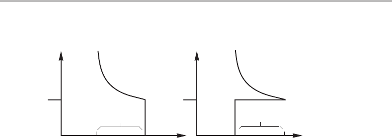
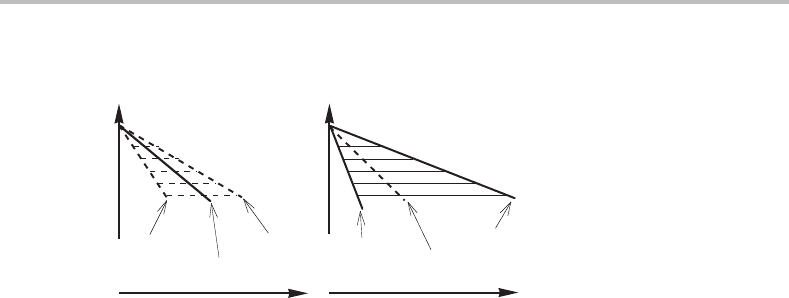
Figure 14.3 Steady-state conditions for a quasi-adiabatic β → α transformation under constant
P. The growing α has the same enthalpy as the initial β.
interface. The growing α should then have a uniform temperature, T
α
,but the tem-
perature may vary inside the parent β. The temperature profile can be illustrated by
Fig. 14.3(a) which has been drawn under the assumption of local equilibrium at the
interface. All of the α phase must be at the equilibrium temperature, T
e
.Inorder for this
to be a steady-state process it is necessary that α has the same enthalpy as the bulk of
the β phase. This is illustrated in Fig. 14.3(b) and the following equations are obtained
if the heat capacity can be approximated as constant and the same in both phases.
H = H
m
+ C
P
(T
β
− T
α
) = 0 (14.7)
T
β
= T
α
− H
m
/C
P
= T
e
− H
m
/C
P
. (14.8)
The reaction can thus be essentially adiabatic if it is possible to change the temperature
of the whole β system to T
e
− H
m
/C
P
before the nucleation of α occurs. This model
thus requires twice as large a T as the truly adiabatic model. This is a demonstration
of the fact that a deviation from local equilibrium results in less need of driving force.
After a transient period, during which an enthalpy spike of height H
m
will develop in
the β phase at the migrating interface, steady-state conditions will be established and
then maintained towards the end of the reaction. The duration of the transient period
and the width of the temperature spike in the parent phase will depend upon the rate of
transformation and the rate of heat flow. We can use the phase diagrams, given below,
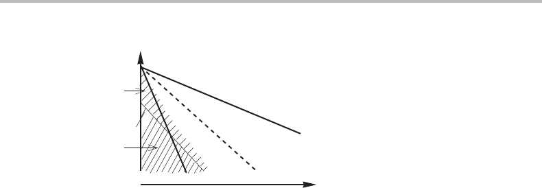
for a summary of our conclusions (see Fig. 14.4).
Point 1 in Fig. 14.4 is the isothermal transformation temperature for β.Aβ phase
cooled just below that point could start to transform to α but the progress of the trans-
formation would be directly controlled by the further extraction of heat from the system.
The growing α phase will be at point 2. If a β phase could be cooled to point 3 before
the transformation starts, then the transformation could, in principle, occur very quickly
and adiabatically and the α phase would be at point 4. However, if the phase interface
does not move with an extremely high velocity, there will be heat conduction into the
remaining β phase and it will no longer be able to transform adiabatically but would
depend upon further heat extraction. Finally, if a β phase could be cooled to point 5
before the transformation starts, then the transformation could occur without any further
heat extraction even if there is time for heat conduction. All of the α formed would be

14.3 Quasi-adiabatic phase transformation 307
α
β
α
β
T
P
P
(α/β)
H
(β/α)
H
(α+β)
H
(α/β)
T
(β/α)
T
(α+β)
T
1
2
3
5
4
2
1
3
4
5
H
m
(a) (b)
Figure 14.4 Phase diagram illustrating the conditions for a quasi-adiabatic transformation in a
unary system. Subscript T indicates isothermal conditions. Subscript H indicates adiabatic
conditions because P is kept constant.
at point 2 and β at the interface would be at point 1. The transformation could occur
in a steady-state fashion where the growing α phase forms at T
e
. The initial β is at a
lower temperature (compare point 2 in the P, T phase diagram with point 5) but has the
same enthalpy (compare point 2 in the P, H
m
phase diagram with point 5). This type of
reaction could be called a quasi-adiabatic transformation. It is interesting to note that it
occurs when the parent phase, by cooling, is entering into the field for the new phase in
the P, H
m
diagram.
It is usually assumed that a transformation starts from a stationary nucleus and picks
up speed during an initial transient period. It would then be natural to expect a situation
somewhat similar to Fig. 14.3 to be established after some short time. It is an interesting
question whetherit could later develop into a trulyadiabatic mechanism. The requirement
would be that the speed becomes so fast that the temperature spike in the parent phase
becomes so thin that it disappears between the atoms. A simple calculation would show
that the thickness should be less than about D/υ,where D is the diffusion coefficient of
heat and υ is the growth rate. This transition turns out to be very unlikely.
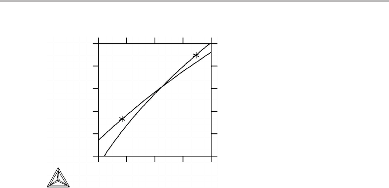
Exercise 14.2
Figure 14.5 gives the relations between S
m
and H
m
for bcc and liquid W. The melting
point is marked with an asterisk for each phase. Evaluate the change of entropy during
quasi-adiabatic melting and solidification.
Hint
The growing phase must be stable in contact with the parent phase at the interface, i.e., it
must grow at the melting temperature. The bulk of the parent phase must be at a different
temperature in order to have the same enthalpy as the growing phase.
Solution
The melting point on the liquid curve (the asterisk) represents the growing liquid and
the bulk of the parent bcc is situated exactly below it. The change of entropy can be read
308 Partitionless transformations
125
120
120 140 160 180
115
110
105
100
100
Enthalpy, H-H
SER
(kJ/mol)
Entropy, S (J/molK)
bcc
Liquid
Figure 14.5 See Exercise 14.2.
as +1.5J/mol, K and for solidification as +2.8J/mol, K. In both cases the entropy is
produced in the thermal spike in front of the interface.
Exercise 14.3
Estimate how fast a transformation should be in order to reach truly adiabatic conditions.
Hint
The diffusion coefficient D for heat conduction is about 10
−5
m
2
/s. The atomic distances
are about 10
−10
m.
Solution
D/υ < 10
−8
yields ν>10
−5
/10
−10
= 10
5
m/s. This is higher than the speed of sound.
14.4 Partitionless transformations in binary system
We shall now examine a partitionless transformation, i.e., a transformation where the
components do not partition between the parent phase and the product, and we shall
find striking similarities with the adiabatic case. We shall use the combined law from
Eq. (3.27) because temperature and pressure will be kept constant in addition to
composition.
Ddξ =−SdT + V dP + µ
i
dN
i
− dG =−dG. (14.9)
In this case G plays the same role as S from Eq. (14.2) under adiabatic conditions. The
driving force for the reaction is D =−dG/dξ and for D = 0wewould have a reversible
reaction which would occur without a change of the Gibbs energy but infinitely slowly.
The reaction could proceed with a measurable rate if D > 0, i.e. dG < 0. Partitionless
14.4 Partitionless transformations in binary system 309
.
.
∆ µ
A
∆µ
B
α
β
x
B
α/β
x
B
β/α
−∆G
m
= G
β
m
− G
α
m
G
m
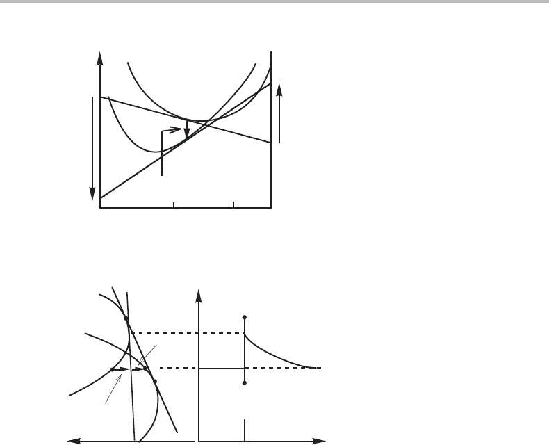
Figure 14.6 Conditions for a true diffusionless transformation.
α
β
x
B
α
β
G
m
d
D
int
D
diff
Figure 14.7 Crude model for deviation from local equilibrium under a quasi-diffusionless
transformation.
transformations were discussed in Section 7.8.Weshall now examine such a reaction in
more detail and discuss two limiting cases depending on whether any diffusion is
involved. In principle, it could be completely diffusionless,acase that is illustrated
in Fig. 14.6.However, there could also be some diffusion, e.g. in a thin pile-up of a
component which is pushed forward in front of the advancing interface. It is illustrated
in Fig. 14.7 and resembles the quasi-adiabatic case in Fig. 14.3 and may be regarded
as quasi-diffusionless. Both cases are illustrated in Fig. 14.8 which can be compared
with Fig. 14.4 for the adiabatic cases. The dashed line in the T, x
B
diagram, denoted
by T
o
, corresponds to the dashed line in the P, H
m
diagram, which showed where α
and β have equal values of H
m
.Onthe T
o
line, α and β have equal values of x
B
and
equal values of G
m
, i.e., a true diffusionless transformation. The other limiting case is
found when there is full local equilibrium at the migrating interface, according to the full
lines in Fig. 14.8(b), similar to the quasi-adiabatic case in Fig. 14.4(b).Itisthe limiting
case of a quasi-diffusionless transformation and could be called local-equilibrium parti-
tionless transformation or simply LE-partitionless transformation. It was discussed in
Section 7.8 and illustrated in Fig. 7.21.
The true diffusionless transformation is easy to understand. If a β alloy is cooled below
the T
o
line, where α of the same composition has the same G
m
value, then G
m
may
310 Partitionless transformations
α
β
µ
B
x
B
T
(β/α)
x
(α/β)
µ
T
(α+β)
x
(α+β)
µ
(β/α)
µ
(α/β)
x
α
β
T
O
(a) (b)
Figure 14.8 Phase diagram for a binary system illustrating the conditions for diffusionless and
LE-partitionless transformations. The full lines show the phase boundaries under equilibrium
(constant T, P and µ
i
). The dashed lines hold if there is no diffusion.
decrease by the β → α transformation even without any change of the composition.
The molar Gibbs energy diagram in Fig. 14.6 demonstrates that µ
B
will increase by
that transformation, which corresponds to the increase of T during the true adiabatic
transformation.
In practice, it is seldom possible to avoid diffusion completely. It would be necessary
that the mathematical width of the pile-up in Fig. 14.7 is below atomic dimensions. The
growth rate should be of the order of D/d or higher. D is the diffusion coefficient and d is
about 10
−10
m. Otherwise, the transformation could not be regarded as diffusionless. On
the other hand, at diffusion-controlled transformations the growth rate may often be low
enough to make the LE-partitionless transformation a reasonably good approximation.
Figure 14.7 demonstrates a more general case where there is some deviation from local
equilibrium at the interface and the compositions at the interface do not fall on the points
of tangency for the common tangent.
In metallic materials there are two well-known partitionless transformations called
‘martensitic’ and ‘massive’. The martensitic transformation is usually very rapid and
comes close to the true diffusionless case but its interface migrates with an atomic
mechanism that creates strong stresses which require a high driving force. This type
of transformation can very well occur far inside the α + β two-phase field but only
at a considerable distance below the T
o
line due to the necessity of a driving force.
The massive transformation is rapid but not extremely rapid. There may be time for
individual atoms to diffuse across the interface and maybe even for a pile-up to form.
This transformation may thus fall well between the two limiting cases.
An interesting problem may be mentioned in this connection. Figure 14.6 demonstrates
that the chemical potential of B increases as it crosses the interface and moves from β
to α. One should ask what forces the B atoms to move against their driving force. In
the LE-partitionless transformation the problem is solved by the presence of the pile-up.
As it moves in front of the migrating interface, it gradually lifts the B atoms to higher
potential as illustrated in Fig. 14.7.For the martensitic transformation the explanation
must be that all atoms cross the interface with some kind of a cooperative mechanism.
Forarapid massive transformation there may not be a sufficiently well developed pile-up
14.5 Partial chemical equilibrium 311
T
β
massive
martensite
T
o
x
B
Figure 14.9 Solution to Exercise 14.4.
and the mechanism of transfer of atoms across the interface must be partly cooperative.
This will be further discussed in Chapters 16 and 17.
Exercise 14.4
Given the phase diagram in Fig. 14.6, mark the regions where one could expect the
massive or the martensitic transformations β → α. Suppose that the martensitic trans-
formation requires an undercooling below T
o
which is independent of the composition
and that the massive transformation occurs with some small deviation from equilibrium.
Hint
Martensite will normally grow much faster because it requires no diffusion. Martensite
would thus predominate in a region where both types of transformation could occur, in
principle.
Solution
The solution is given in Fig. 14.9.
14.5 Partial chemical equilibrium
In a ternary alloy it could very well happen that one of the elements diffuses very much
faster than the other two, for example if it is an interstitial solute. It is then possible that a
new phase forms with a different content of the mobile element but without a change of
the relative contents of the other two. Such a transformation would be partly partitionless.
Hultgren [26] proposed that it could even occur without any diffusion of the latter two
elements and used the term paraequilibrium to describe the local equilibrium at the
phase interface under such a transformation. We shall now examine that kind of local
equilibrium. Hultgren studied systems with Fe, C and a metallic solute which we shall
denote by M. We shall keep those symbols but Fe could represent any element, C any
mobile element and M any element as sluggish as Fe.

312 Partitionless transformations
Under full local equilibrium at a phase interface, there is no driving force on the
interface as shown by the following form of the combined law Eq. (3.33),
Ddξ =−SdT + V dP − N
i
dµ
i
= 0, (14.10)
because T, P and all µ
i
have the same values on both sides of the interface. When
a transformation occurs under paraequilibrium, µ
C
has the same value on both sides
because C is very mobile, but µ
Fe
and µ
M
have different values. Instead, u
Fe
and u
M
have the same values if u
i
is defined as N
i
/(N
Fe
+ N
M
). It is thus useful to consider the
combined law in a new form which can be derived as follows,
Ddξ =−SdT + V dP − N
i
dµ
i
(14.11)
Ddξ/(N
Fe
+ N
M
) =−S
m12
dT + V
m12
dP − u
i
dµ
i
± (µ
Fe
du
Fe
+ µ
M
du
M
)
=−S
m12
dT + V
m12
dP − u
C
dµ
C
+ µ
Fe
du
Fe
+ µ
M
du
M
− d(u
Fe
µ
Fe
+ u
M
µ
M
).
(14.12)
The subscript ‘m12’ is explained in Section 4.3. Under paraequilibrium dT = dP =
dµ
C
= du
Fe
= du
M
= 0 and we find
Ddξ/(N
Fe
+ N
M
) =−d(u
Fe
µ
Fe
+ u
M
µ
M
) = 0. (14.13)
The driving force has here been put to zero for a transformation occurring under parae-
quilibrium conditions because, ideally, paraequilibrium is supposed to be a kind of local
equilibrium. It is thus necessary that u
Fe
µ
Fe
+ u
M
µ
M
has the same value on both sides
of the interface. Of course, T, P and µ
C
must also have the same values on both sides.
The new quantity that must have the same value in both phases is simply an average
value for Fe and M, as if they together have formed a new element. The quantity can be
written in various ways because G
m12
= u
i
µ
i
,
u
Fe
µ
Fe
+ u
M
µ
M
= G
m12
− u
C
µ
C
=
G
m
− x
C
µ
C
1 − x
C
. (14.14)
Suppose the three elements can form a compound θ of the formula (Fe, M)
a
C
c
with
a + c = 1. For paraequilibrium between θ and a solution phase, γ,wefind
G
m
− cµ
C
a
θ
=
G
m
− x
C
µ
C
1 − x
C
γ
. (14.15)
It should be noted that u
Fe
µ
Fe
+ u
M
µ
M
is a characteristic state function. It was actually
derived in Section 13.6 in a slightly different way and written as G − N
C
µ
C
.
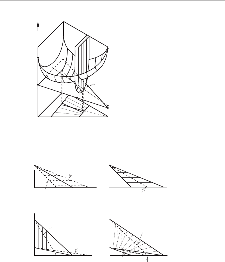
In a molar Gibbs energy diagram the tie-line between the two phases in paraequilibrium
is directed towards the C corner. It falls on a common tangent line to the two Gibbs
energy surfaces but not on the common tangent plane. Figure 14.10 demonstrates that
the common tangent line for paraequilibrium, which must go through the C axis, is
situated above the common tangent plane that holds for full equilibrium. The chemical
potential of C will thus be slightly different.
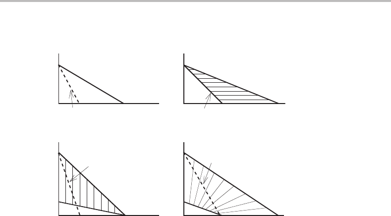
Figure 14.11(a)–(d) gives various versions of the phase diagram showing the equilib-
rium between two solution phases, α and γ,atsome convenient T and P values. Instead
of using the chemical potentials, µ
C
and µ
M
,asaxes the chemical activities, a
C
and
a
M
,have been used in order to make the diagram show low contents of C and M where
the chemical potentials would approach negative infinity. It is interesting to note that
14.5 Partial chemical equilibrium 313
A
B
C
.
µ
A
µ
C
.
α
θ
G
m
o
G
α
A
o
G
α
C
G
θ
B
a
C
c
Figure 14.10 Molar Gibbs energy diagram for a ternary system illustrating the paraequilibrium
conditions. The common tangent line from the C axis is situated above the common
tangent plane.
(α/γ)
p
(α+γ)
p
(α/γ)
p
(γ/α)
p
α
α
α
α
γ
γ
γ
γ
(γ/α)
p
(γ/α)
p
(α/γ)
p
.
a
C
x
C
x
C
a
C
x
M
x
M
a
M
a
M
T
o
(a) (b)
(d)(c)
Figure 14.11 The phase diagram for a ternary system at constant T and P, drawn with different
sets of axes in order to illustrate the paraequilibrium conditions (dashed lines), assuming that C
is the only mobile component.
Figs 14.11(a) and (b) are very similar to Fig. 14.6 but T has been replaced by a
C
.Infact,
the two reactions are very similar because the additional component in the present case
is compensated by the temperature being kept constant.
The point of equal Gibbs energy of α and γ on the binary Fe–M side has been marked
as T
o
in Fig. 14.11(d) because it belongs to the T
o
line in the binary T, x
M
diagram. It
is important to note that the two paraequilibrium phase boundaries fall inside the full
equilibrium two-phase field. This is a general rule.
314 Partitionless transformations
(γ/α)
α
α
α
γ
γ
γ
α
γ
(γ/α)
quasi-para
(γ/α)
quasi-para
(γ/α)
quasi-para
a
C
x
C
a
M
x
M
x
M
x
C
a
C
(a) (b)
(d)(c)
Figure 14.12 Dashed lines show the conditions for quasi-paratransformation γ → α in a ternary
system with a very mobile component C.
As in the binary case, discussed in the preceding section, we should also examine
the possibility of obtaining a partitionless (here of Fe and M) transformation under full
local equilibrium. That should be possible if there is a composition spike in front of the
migrating interface. The critical limit for a γ → α transformation to take place under
such quasi-paraequilibrium conditions is that the initial γ phase falls on the α phase
boundary in the a
C
,x
M
phase diagram (see Fig. 14.12(b)). Again the conclusions are
very similar to the previous case. However, in the present case it is more common to use
an x
C
,x
M
phase diagram (see Fig. 14.12(d)). It should be noticed that the critical limit
for a quasi-paratransformation will not fall on the α phase boundary in such a diagram
because γ and α must have the same µ
C
(i.e. a
C
) and that requires different x
C
.
Finally, we may compare the critical limit for the two partitionless kinds of growth
by means of Fig. 14.13.Itisinteresting to note that paraequilibrium with its devi-
ation from full local equilibrium requires less supersaturation of the parent γ. This
is in agreement with a more general principle mentioned in Section 14.1.Inprac-
tice, one should expect something between quasi-paraequilibrium and paraequilib-
rium depending on the mobilities of Fe and M, especially inside the interface, rela-
tive to the rate of migration of the interface. In the next section we shall give a more
detailed account of some phase transformations assuming that they take place under
quasi-paraequilibrium.
Exercise 14.5
In Fig. 14.11 there are two diagrams with dashed tie-lines. They hold for paraequilibrium.
In the other two diagrams the corresponding tie-lines have not been drawn. Indicate where
they should fall.
