Heard D.E. (editor) Analytical Techniques for Atmospheric Measurement
Подождите немного. Документ загружается.

152 Analytical Techniques for Atmospheric Measurement
300 350 400 450 500 550 600 650
0
6
0
6
0
4
0
4
0
60
120
0
60
120
0
60
120
0
60
120
0
100
200
0
100
200
0
60
0
60
0
20
0
20
Wavelength (nm)
300 350 400 450 500 550 600 650
0
100
200
0
100
200
SO
2
HONO
BrO
OClO
IO
OIO
I
2
NO
3
σ′/10
–19
cm
2
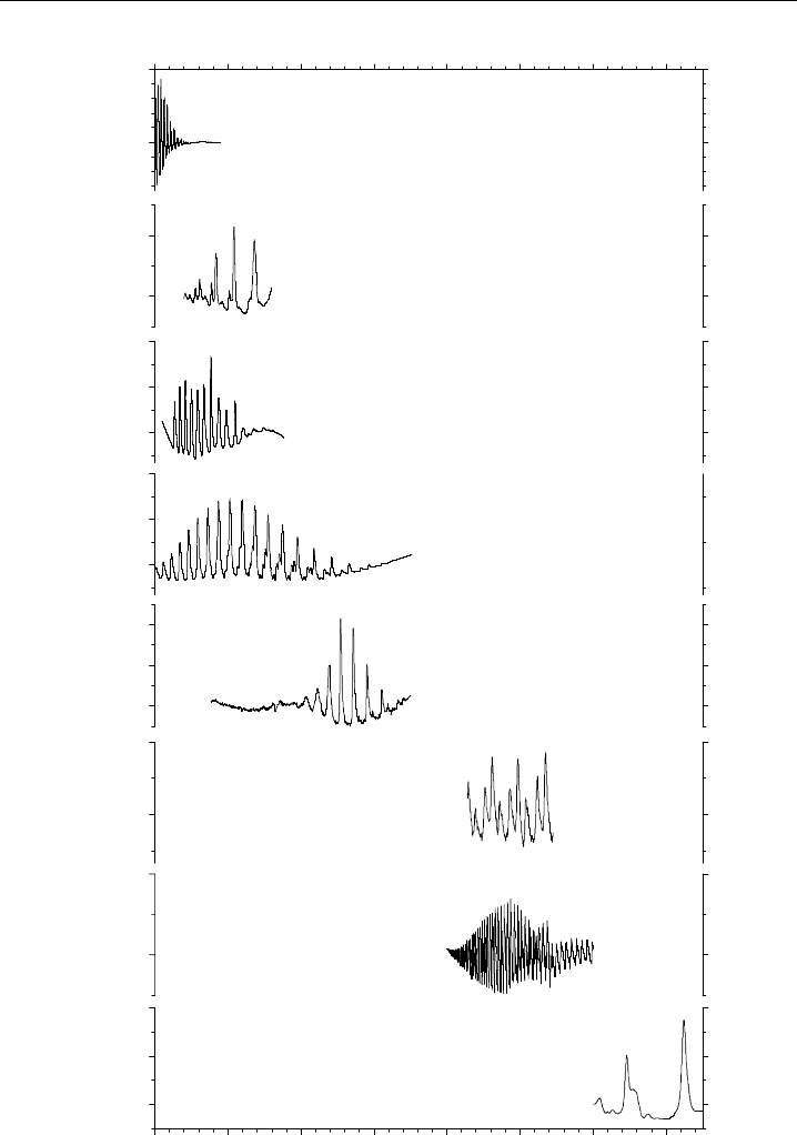
Figure 3.2 Examples of differential absorption cross-section spectra in the UV/visible region for a
selection of important atmospheric species.

UV-Visible Differential Optical Absorption Spectroscopy 153
The molecular absorption cross-sections used as reference spectra when analysing
atmospheric spectra are generally taken from the literature. Because
is related
directly to (Equation 3.7), the concentrations derived from equation (3.11) are then
traceable back to laboratory measurements of . This is particularly important in
the case of absorption cross-sections for radical species (e.g. BrO, NO
3
), whose absolute
concentrations and hence cross-sections are often challenging to measure in the laboratory
but where expert evaluations of several studies are available (Wahner et al., 1988; Sander
& Friedl, 1989; Yokelson et al., 1994). The recommended literature cross-section, which
will usually have been recorded at much higher resolution than required for atmospheric
spectroscopy, must then be convolved with the instrument function F of the spectrometer
employed in a particular DOAS instrument. That is, the resolution of the literature
cross-section will be degraded to match that of the DOAS spectrometer. For instance,
the DOAS reference cross-section, , can be expressed as:
= F
HR
(3.12)
where
HR
is the high resolution literature cross-section. The function F is typically a
moving average of the high resolution spectrum around the central wavelength . The
width and weighting of the average is usually obtained by measuring the wavelength
profile of an atomic emission line (from a low pressure Hg/Ne lamp). Alternatively,
reference spectra can be measured directly by placing appropriate gas cells into the light
path of the DOAS instrument. This has the advantage that an instrument function is then
not required for fitting to atmospheric spectra, and the wavelength calibration should
exactly match atmospheric spectra taken with the same instrument. However, absolute
calibration of the reference cross-section still requires de-convolving a high resolution
spectrum from the literature.
A further consideration is that absorption cross-sections are quite often temper-
ature dependent, and this needs to be accounted for when fitting reference spectra to
atmospheric spectra. For example, the H
2
O cross-section has been shown to vary linearly
with temperature (Aliwell & Jones, 1996a):
T
=
T
0
+T −T
0
T
(3.13)
where
T
0
refers to the cross-section at a reference temperature T
0
. The differential
in the second term of Equation 3.13 can then be fitted as a separate spectrum, with the
factor T −T
0
either known or optimised in the fitting procedure.
3.2.4 Application to atmospheric measurements
There are a large number of species which play an important role in atmospheric chemistry
and have absorption cross-sections in the near-UV/visible region suitable for detection
by DOAS. Table 3.1 lists the molecules that have been observed by DOAS, including the
wavelength regions employed and the detection limits achievable with a state-of-the-art
instrument.

154 Analytical Techniques for Atmospheric Measurement
Table 3.1 Atmospheric species measured by DOAS in the UV/visible
spectral range
Species Wavelength interval (nm) Detection limit
a
(ppt)
O
3
300–335 1900
NO 200–230 50
b
NO
2
330–500 50
NO
3
623–662 0.4
HONO 330–380 30
NH
3
200–220 150
b
SO
2
290–310 10
HCHO 260–360 50
CS
2
290–310 900
Benzene 230–280 200
b
Toluene 260–280 250
b
Naphthalene 310–320 100
Phenol 260–280 20
b
p-Cresol 260–290 50
b
OH 308 0.06
c
ClO 260–320 5
OClO 300–450 0.8
d
BrO 300–370 2
OBrO 450–550 1.5
d
IO 415–450 1
OIO 535–575 4
I
2
535–575 9
a
For a 5 km pathlength, assuming a minimum detectable optical density of 10
−4
;
ppt =parts per trillion 10
−12
.
b
For a 1 km pathlength and an optical density
of 10
−3
, since absorption by O
3
and O
2
cause significant attenuation of light
at wavelengths below 280 nm.
c
For a 2 km pathlength and a spectral resolution
of 17 ×10
−3
nm.
d
Stratospheric constituent, whose column abundance has been
measured by ground-based, ballon-borne or satellite-borne DOAS instruments.
3.3 DOAS using artificial light sources
3.3.1 Broad-band light sources
This technique was developed at the end of the 1970s by Platt and Perner (Platt et al.,
1979, 1980a,b; Platt & Perner, 1980, 1983), and since then has been widely used for
measuring many of the species in Table 3.1 (Hausmann & Platt, 1994; Platt, 1994; Brauers
et al., 1995; Plane & Smith, 1995; Smith et al., 1995; Stutz & Platt, 1996; Tuckermann
et al., 1997; Alicke et al., 1999; Hebestreit et al., 1999; Allan et al., 2001; Saiz-Lopez &
Plane, 2004).
3.3.1.1 Experimental set-up
An LP-DOAS instrument comprises a transmitter, consisting of a high pressure Xe or
incandescent lamp at the focal point of a parabolic or spherical mirror to provide a highly

UV-Visible Differential Optical Absorption Spectroscopy 155
collimated light beam, and a receiver, consisting of a telescope coupled to a spectrometer,
and a detector where the dispersed spectrum is recorded. In early DOAS instruments, the
transmitter and the receiver were placed at opposite ends of the light path (Platt et al.,
1979), and a slotted-disk scanning device was employed as a detector in conjunction
with a photomultiplier tube (Platt, 1994). Since the late 1980s, multiplexing detectors
such as the photodiode array (PDA) and the charge coupled device (CCD) have replaced
photomultiplier tubes. Another significant development in DOAS design has been to
place the transmitter and the receiver in the same location, and fold the light path using
a reflector (the total light path is then twice the distance between the DOAS and the
reflector). In order to avoid the technical challenge of pointing a plane mirror with
sufficient accuracy over an optical path of several kilometres, either retro-reflectors (which
contain three mutually orthogonal plane mirrors) or corner-cubes have been used. Both
types of reflectors utilise three internal reflections to return light back to its source with
high accuracy (better than a few arc seconds is necessary if the reflector is more than
2 km from the source). These reflectors also have a large acceptance angle so that accurate
pointing at the source is not necessary.
DOAS instruments using a folded light path have either placed the receiver alongside
the transmitter (Plane & Nien, 1992; Hausmann & Platt, 1994) or combined them in
a coaxial design in a single telescope (Axelsson et al., 1990; Carslaw et al., 1997a; Allan
et al., 1999, 2000a; Saiz-Lopez et al., 2004). There are a number of important reasons
for co-locating the transmitter and the receiver. First, only one location providing shelter
and electrical power is needed, and the reflector can be placed in quite inaccessible
terrain. Second, optimal processing of the atmospheric spectrum requires a spectrum
of the lamp in the transmitter, unattenuated by transmission through the atmosphere
(see p. 157). The lamp spectrum can be recorded on a routine basis by using an optical
bypass to steer the light directly from the lamp to the spectrometer, if they are co-located.
Third, by folding the light the optical path is doubled for the same path through the
atmosphere. This reduces complications that might arise from chemically inhomogeneous
air masses over very long distances. Fourth, there is a reduction in light losses due to
divergence of the light beam because the reflected light converges back to its source.
Also, light losses due to atmospheric scintillations occur on a much slower time scale
than the time taken for the light to be transmitted and reflected. The reflected beam will
therefore follow the same refracted path through the atmosphere and thus losses due to
scintillations will be significantly less than for an unfolded path of double the length.
Finally, the acceptance angle of a retro-reflector or corner-cube is typically about 20
,so
that several DOAS instruments can use the same reflector without significant interference
(Plane & Smith, 1995).
When designing a DOAS instrument there are a number of considerations, such as
the type of lamp, the optimal length of the light path, the choice of spectral resolution
and detector, and the desired degree of automation (Platt, 1994; Plane & Smith, 1995).
The instrument illustrated in Figure 3.3 is a design that we have used in a variety of
remote locations over the past decade (Carslaw et al., 1997a,b; Allan et al., 1999, 2000a,b,
2001; Saiz-Lopez & Plane, 2004; Saiz-Lopez et al., 2004). It employs a coaxial design
with a 32 cm diameter f/6 Newtonian telescope that houses both the transmitting and
the receiving optics. The broadband light beam is powered by a 450 W Xe lamp, housed
on the side of the telescope at the focal point of the spherical primary mirror. The
156 Analytical Techniques for Atmospheric Measurement
Atmospheric light path
Optical bypass
Arc
lamp
CCD
Corner-cube array
Czerny-Turner spectrometer
Shutter
Optical filter
Optical bypass
Reference gas absorption cell
CCD control
Stepper motor control
Central computer
instrument control
32 cm Newtonian telescope
Plane mirrors
Hg or Ne
lamp
Effective optical path:
2 × path length
Triple grating
turret
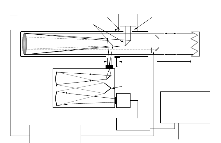
Figure 3.3 Schematic diagram of a coaxial LP-DOAS instrument where a single telescope houses both
the transmitting and receiving optics, and the light beam is folded back by an array of corner cube
reflectors.
outgoing beam is folded back to the telescope by an array of solid quartz corner-cubes
(accuracy < 5 arc seconds). The received light is then focused onto a quartz optic fibre
bundle. A mode mixer can be used to obtain a more uniform intensity distribution at
the fibre exit into the spectrometer, independent of the light distribution at the entrance
to the fibre bundle (Stutz & Platt, 1997). The light is then dispersed through a 0.5 m
Czerny-Turner spectrometer, using either a 1200 or 600 groove mm
−1
grating which
produces spectral widths of about 35 or 70 nm, respectively, on a typical PDA or CCD
detector. The resolution is then about 0.2–0.4 nm. CCD cameras have increasingly been
employed as detectors in DOAS instruments. One reason is that CCD chips possess high
quantum efficiencies >20% in the near-UV, where a number of relevant atmospheric
species have suitable absorption features (Table 3.1). High detection efficiency in the
UV is important for making measurements with good signal-to-noise ratio, because the
intensity of the transmitted light is substantially reduced by Rayleigh, Mie and molecular
extinction, and the arc lamp intensity falls at wavelengths below 400 nm. CCDs tend
to have large dark currents, so it is important to cool the devices (modern cameras
are capable of reaching and maintaining temperatures down to −70
C, by combining a
multi-stage Peltier thermoelectric cooler in an evacuated chamber). A final consideration
is that étaloning can be created by interference on the surface-protective coating of some
chips. We have found that front-illuminated CCDs largely eliminate this problem in
contrast to back-illuminated chips.
The instrument shown in Figure 3.3 also contains a number of automated optical
components. A stepper motor in the lamp housing allows the light to be shuttered off
in order to record scattered light spectra from the atmosphere. An optical cut-on filter
(>600 nm) can also be inserted into the light beam when measuring the nitrate radical

UV-Visible Differential Optical Absorption Spectroscopy 157
NO
3
at night (this prevents photolysis of the radical at shorter wavelengths in the light
beam). A second stepper motor controls an optical bypass for recording unattenuated
lamp spectra. Motorised translational stages are used to align the quartz optic fibre bundle
with the image of the light beam received in the telescope. Finally, a motorised filter
wheel inserts combinations of neutral density and cut-on filters into the light beam at
the entrance of the spectrometer. These filters are used to attenuate the light entering the
spectrometer to avoid saturating the CCD, and also to eliminate short wavelength light
being diffracted in second order onto the detector.
3.3.1.2 Spectral de-convolution
Although different approaches have been used to analyse atmospheric spectra (Platt,
1994; Plane & Smith, 1995; Camy-Peyret et al., 1996; Aliwell et al., 2002), they are
conceptually very similar. Analysis procedures mainly use either polynomials for the
generation of the differential optical spectra and reference cross-sections or Fourier
transforms with combinations of low- and high-pass filters. Here we will describe the
spectral de-convolution procedure originally developed by Plane and Nien (1992).
Figure 3.4 illustrates the de-convolution of an atmospheric spectrum in the 637–677 nm
wavelength region, in order to measure NO
3
. Panel (a) shows a raw air spectrum (solid
line) which is dominated by the ro-vibrational structure of an overtone band of H
2
O
(Rothman et al., 2003). The raw spectrum is the sum of the transmitted intensity of
the DOAS light beam and scattered light (usually only significant during the day). In
the first stage of the de-convolution procedure, a processed atmospheric spectrum is
generated by removing the scattered light contribution and any spectral features of the
lamp source in the transmitter. This is achieved by collecting a set of three different
spectra: an atmospheric + scattered light spectrum A; a scattered light spectrum S
obtained by shuttering off the Xe lamp; and a lamp + atmospheric + scattered light
spectrum L obtained by opening an optical bypass which directs some of the Xe light
directly into the receiving telescope. In order to reduce errors caused by fluctuations in
the lamp and the scattered light intensity, and by changing atmospheric concentrations,
the three spectra are collected in turn, with each spectrum being accumulated for 20 s
over a period of typically 10 min. The processed spectrum is then given by:
I
pr
=
A −S
L −A
(3.14)
It is, therefore, the spectrum transmitted through the atmosphere, normalised by
dividing by the unattenuated lamp spectrum. In principle, this procedure removes the
Xe lamp spectral features contained in the transmitted spectrum and the pixel-to-pixel
variability in light response across the surface of the CCD. Also, the three spectra
contain the same dark current and electronic offset from the analog-to-digital converter
in the detector, so these cancel by subtraction in the numerator and denominator of
Equation 3.14.
The next step in the de-convolution procedure is to convert I
pr
into a differential
optical density OD
spectrum. This is achieved by Fourier transforming the spectrum,
applying a low-pass filter, and then performing an inverse transform to obtain the broad-
trend spectrum, I
0
(see Section 3.2.2). In panel (a) of Figure 3.4 the processed spectrum
158 Analytical Techniques for Atmospheric Measurement
2e + 7
a
b
c
d
CountsDifferential ODDifferential OD
2e – 2
0
3e
– 3
640 650
Wavelength (nm)
660 670 680
3e
– 3
0
0
0.4
Atmosphere / Lamp
0.5
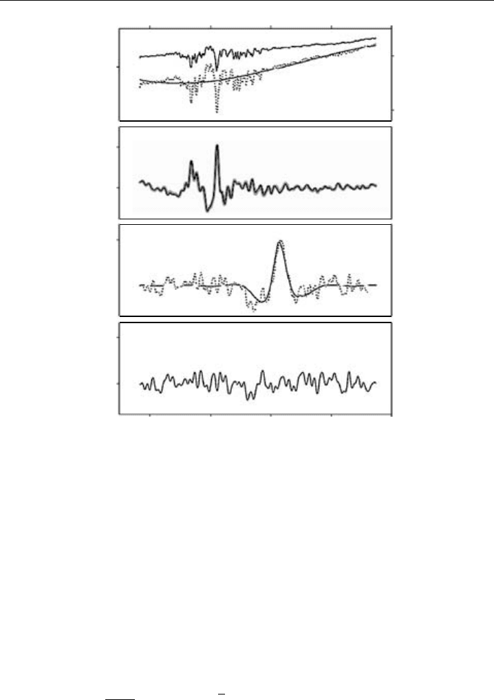
Figure 3.4 An atmospheric measurement of NO
3
: (a) raw atmospheric spectrum (solid line, left-hand
axis), and the processed atmospheric spectrum (grey line, right-hand axis) with a broad trend line obtained
from a Fourier transform with a low-pass filter; (b) observed atmospheric optical density (black line) and
fitted reference spectra (grey thick line); (c) atmospheric differential OD spectrum (grey line) after H
2
O
absorption has been fitted out but NO
3
contribution remains – the solid line is the fitted NO
3
reference
differential cross-section once it has been degraded to the spectrometer resolution, corresponding to a
mixing ratio of 11 ppt; (d) residual spectrum obtained after the known absorbers have been removed,
indicating a minimum detectable mixing ratio for NO
3
of 0.4 ppt.
(grey line) is plotted together with I
0
. The OD
spectrum is then given by the sum of the
n individual absorber contributions at each wavelength (Equation 3.10), to which can be
added a first-order polynomial that is optimised in the fitting procedure to take account
of any residual off-sets (ideally, and should be zero):
OD
= ln
I
0
I
pr
= l
n
i=1
i
c
i
+ + (3.15)
Note that the reference cross-sections
i
should be derived from absolute cross-
sections with the same Fourier transform/low-pass filter routine that is applied to the
processed atmospheric spectrum. Since OD
is measured over a large number of

UV-Visible Differential Optical Absorption Spectroscopy 159
wavelengths in a multiplexing detector (typically 1024 with a CCD or PDA), but the
unknowns in Equation 3.15 are the n molecular concentrations
c
i
and the parameters
and (usually less than 10 unknowns in total), the solution of the Equation 3.15
is greatly over-determined. An optimal solution can be obtained from a least squares
fitting routine that employs singular value decomposition (Press et al., 1986). The analysis
software should also permit shifting and stretching of the reference spectra with respect
to wavelength, in order to correct for any differences in wavelength calibration between
the DOAS spectrometer and the literature cross-sections. Note that this is less necessary
if spectral calibrations are performed in the field using cells filled with reference gases.
The main absorbers in the 637–677 nm range are H
2
O and NO
3
. Once the total OD
spectrum is obtained, both species need to be fitted out in the de-convolution procedure.
Fitting a reference H
2
O spectrum is complicated because some of the rotational lines
in the vibrational overtone band around 651.5 nm are usually saturated at the column
densities of H
2
O found over several kilometre optical path in the lower troposphere.
Hence, the absorption bands do not follow the Beer–Lambert law (Aliwell & Jones,
1996a). One solution to this problem is to take the high resolution H
2
O reference
spectrum from the HITRAN database (Rothman et al., 2003), and compute a library of
H
2
O reference spectra, degraded to the spectrometer resolution, over a range of expected
H
2
O column densities and atmospheric temperatures. The fitting routine then finds the
H
2
O spectrum that best fits the observed atmospheric spectrum. Panel (b) of Figure 3.4
shows the atmospheric OD
spectrum together with the overall fitted reference in the
region used for NO
3
analysis. The reference spectrum for NO
3
is calculated from the
reported cross-section (Yokelson et al., 1994) of the B
2
E
–X
2
A
2
absorption band at
662 nm. In panel (c) of Figure 3.4, the atmospheric OD
spectrum is shown with the
fitted H
2
O reference spectrum subtracted out (grey line), together with the fitted NO
3
reference. Finally, the best fit is achieved when all known spectral features are removed,
leaving the structureless residual spectrum shown in panel (d) of Figure 3.4(d).
In the particular case of NO
3
, use can be made of the fact that the lifetime of the
radical with respect to photodissociation is just a few seconds during the day (DeMore
et al., 1997), so a daytime spectrum will not contain any significant NO
3
absorption
and can be used as a reference (Platt, 1991; Allan et al., 2000b). The resulting division
is analysed in the same manner as the processed spectrum, described above. Figure 3.5
is an example of the nocturnal time-profile of NO
3
measured by an LP-DOAS at Mace
Head, Ireland, shown together with its rate of production (thick dotted line) calculated
from the measured NO
2
and O
3
concentrations. Note the appearance of the radical after
sunset, and the rapid disappearance due to photolysis, at sunrise.
3.3.1.3 Estimating errors and detection limits
The uncertainties in the retrieved column densities, and the detection limits of a DOAS
instrument, are determined by a number of factors including the size and structure of
the differential absorption cross-sections, the number of absorbers in the spectral region,
the optical path length, and the intensity of the light signal transmitted through the
atmosphere. Contributions to the systematic uncertainty include errors in the absolute
absorption cross-sections of the reference spectra, and error in the length of the optical
path, although with modern global positioning systems (GPS) this should not be significant.
160 Analytical Techniques for Atmospheric Measurement
0
5
10
15
20
25
19:36 20:48 22:00 23:12 0:24 1:36 2:48 4:00 5:12 6:24
Time
/ GMT
[NO
3
] / ppt
Sunset: 20.35
Sunrise: 04.57
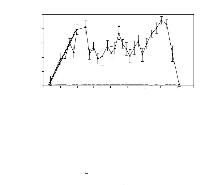
Figure 3.5 Example of NO
3
nocturnal behaviour as measured by LP-DOAS over a pathlength of 8.4 km
at the remote coastal location of Mace Head, Ireland in 2002. The detection limit of the instrument is
plotted as grey broken lines. The rate of production of NO
3
calculated from in situ measurements of NO
2
and O
3
is plotted after sunset (thick dotted line).
A measure of the goodness of fit in the de-convolution analysis is provided by a
chi-square
2
significance analysis:
2
=
2
1
OD
−l
n
i=1
i
c
i
+ +
2
m −1
(3.16)
where m is the number of wavelength intervals between
1
and
2
(elements of the
detector), and the other terms are defined in Equation 3.15. The smaller the
2
is, the
better the fit of the reference spectra to the atmospheric spectrum, since less structure
remains in the residual spectrum. The statistical standard errors of the retrieved concen-
trations are calculated directly from the singular value decomposition routine (Press et al.,
1986), and assume that the structures remaining in the residual are random. These errors
are weighted by the
2
distribution and the m −n degrees of freedom of the system –
where n is the number of fitted parameters or unknowns, and m is the number of linear
equations (i.e. number of detector elements). Hence, the least-squares fitting process
determines a 1 statistical error that normally underestimates the overall error, since the
systematic errors discussed above also need to be included.
Often, consistent structures appear in a sequence of residual spectra. On rare occasions
this might indicate the presence of molecular absorption features from a new species not
included in the de-convolution routine (Equation 3.15). However, there are several more
likely causes. First is incorrect matching of the spectral features between the reference
spectra, often taken from the literature where they will have been recorded under different
resolutions and conditions (pressure and temperature), and the atmospheric spectrum.
This problem is more common when working in spectral regions where several reference
spectra are simultaneously fitted in the de-convolution. Another cause of structures in
the residual spectrum is incomplete removal of spectral features from the light source in
the DOAS transmitter. The source is usually a Xe arc lamp, and the problem is that when

UV-Visible Differential Optical Absorption Spectroscopy 161
using an optical bypass arrangement to obtain the lamp spectrum (e.g. see Figure 3.3),
the image of the arc is larger than the entrance to an optic fibre or the spectrometer slits.
There are large temperature gradients and hence variations in spectral output across a Xe
arc, so the spectrum of the portion of the arc sampled by the bypass can be significantly
different from the atmospheric spectrum, which is dominated by output from the hottest
(and brightest) part of the arc. This will then lead to lamp structure remaining in the
processed spectrum (Equation 3.14), and hence in the residual spectrum (Allan et al.,
2000a). If consistent structures are present in a sequence of residual spectra, these can
be averaged to yield an ‘instrumental reference’ spectrum, which can then be fitted to
the processed atmospheric spectrum together with the molecular reference spectra (Allan
et al., 2000a). This procedure often leads to a substantial reduction in the error and
detection limits of trace species, without any significant effect on the retrieved column
densities.
The minimum detectable OD can be estimated from the root mean square of the
residual (Plane & Smith, 1995):
OD
min
=
2
m −1
(3.17)
The detection limit of an individual species can then be estimated from Equation 3.11.
Note that the detection limit will depend on the atmospheric conditions affecting light
transmission and scattered sunlight (i.e. precipitation, clouds and time of day). This
is because
2
tends to vary inversely with the light intensity transmitted through the
atmosphere to the detector, and
2
is roughly proportional to the level of scattered light.
In principle, under conditions of good atmospheric visibility a minimum detectable OD
of ∼1 ×10
−4
can be achieved (Platt, 1994; Plane & Smith, 1995).
3.3.1.4 Application to atmospheric measurements
The DOAS technique has been in use since the late 1970s, and has made a significant
contribution to the understanding of atmospheric chemistry (Platt, 1994; Plane & Smith,
1995). Originally, Noxon and co-workers (Noxon, 1975; Noxon et al., 1978, 1980) used
an LP-DOAS instrument to measure NO
2
and NO
3
with the aim of complementing their
stratospheric measurements (Section 3.4.1). However, it was Platt, Perner and co-workers
(Perner & Platt, 1979; Platt et al., 1979; Platt & Perner, 1980; Platt et al., 1980a,b; Platt
& Perner, 1983) who made many of the significant early advances. They first reported
simultaneous observations of HCHO, O
3
and NO
2
in the boundary layer (Platt et al.,
1979), followed by measurements of HNO
2
and SO
2
(Perner & Platt, 1979; Platt & Perner,
1980). They also made the first direct measurement of NO
3
in the troposphere (Platt
et al., 1980b).
Since the last major reviews of the DOAS technique in the mid-1990s (Platt, 1994;
Plane & Smith, 1995), a major intercomparison of different LP-DOAS designs and
software retrieval algorithms has been published (Camy-Peyret et al., 1996). In terms of
atmospheric measurements, the most striking advances with DOAS have been pioneering
observations of key halogen species in the lower troposphere. First, measurements of BrO
were reported in the Arctic boundary layer during springtime (Hausmann & Platt, 1994);