Hawkes P.W., Spence J.C.H. (Eds.) Science of Microscopy. V.1 and 2
Подождите немного. Документ загружается.

Chapter 10 Aberration Correction 715
conjugates and are also conjugate to a plane close to the coma-free
plane of the probe-forming lens. In this way, the fi fth-order geometric
aberrations of the combination of corrector and probe-forming lens can
be eliminated. Software will adjust the various components systemati-
cally. The evolution of the corrector, which has been fi tted to many VG
STEMs, to the two SuperSTEMs at Daresbury, and to the Nion STEM,
can be studied in the following publications: Krivanek et al. (1997a,b,
1998, 1999a,b, 2000, 2001, 2002, 2003, 2004), Dellby et al. (2000, 2001),
Batson et al. (2002), Batson (2003), Lupini et al. (2003), Pennycook et al.
(2003), Nellist et al. (2004a,b), Dellby et al. (2005), Bacon et al. (2005),
Krivanek et al. (2005), and Nellist et al. (2006). Figure 10–6b shows
schematically the Nion corrector incorporated in a STEM. The quadru-
pole–octopole corrector designed for an FEI STEM/TEM is described
by Mentink et al. (2004).
3.2.2 Sextupole Correctors
Sextupoles were not among the correctors envisaged by Scherzer in his
1947 paper. In 1965, it was pointed out that the third-order aberrations,
including of course the spherical aberration, of sextupoles have the
same dependence on gradient in the object plane as that of a round lens
(Hawkes, 1965a). However, the fact that the lowest order optical effect
of sextupoles is not linear, as it is in round lenses and quadrupoles, but
quadratic seemed to rule out any hope of using them for aberration
correction. It was not until 1979 that combinations of sextupoles and
round lenses from which the quadratic effects had been eliminated by
compensation were proposed and subsequent developments have con-
fi rmed that such correctors are suitable for incorporation into transmis-
sion electron microscopes. As we have seen, the second-order effect of
a sextupole is characterized by four terms of the form ∫H(z)h
3−n
k
n
dz, in
which H(z) represents the fi eld distribution in the (electrostatic or mag-
netic) sextupole and h(z), k(z) are two linearly independent solutions of
the familiar paraxial equation for round lenses (these solutions collapse
to straight lines in the absence of any round lens component). The
integer n takes the four values 0, 1, 2, and 3. All four terms can be made
to vanish by suitable choice of the symmetry of the confi guration; the
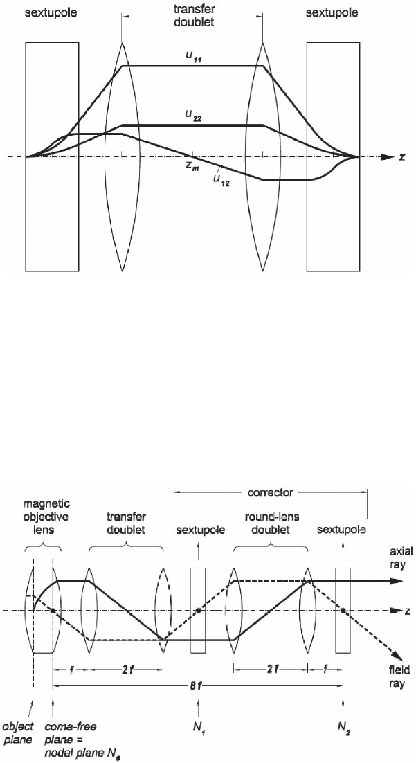
simplest is shown in Figure 10–7. Before coupling such a device to a
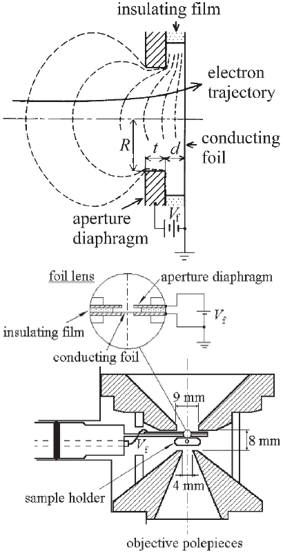
microscope objective, we must, however, ensure that the coma-free
condition is satisfi ed. The (isotropic) coma-free plane of an objective is
situated within the lens fi eld and must hence be imaged onto the front
focal plane of the round-lens doublet in the corrector by means of
another doublet (Figure 10–8). If it should be necessary to eliminate the
anisotropic coma as well as the isotropic coma, an objective design in
which two coils are used in tandem would have to be adopted (Rose,
1971b). Sextupole correction may be traced in the following articles (in
addition to the early publications already cited): Haider et al. (1982, 1995,
1998a–c), Rose (1990b, 2002a,b), Haider and Uhlemann (1997), Haider
(1998, 2000, 2003), Foschepoth and Kohl (1998), Uhlemann et al. (1998),
Urban et al. (1999), Müller et al. (2002), Kabius et al. (2002), Lentzen et
al. (2002), Liu et al. (2002), Benner et al. (2003a,b, 2004a,b), Chang et al.
(2003), Hosokawa and Sawada (2003), Hosokawa et al. (2003), Jia et al.
716 P.W. Hawkes
(2003), Sawada et al. (2004a–c), Haider et al. (2004), Hartel et al. (2004),
Titchmarsh et al. (2004), Hutchison et al. (2005), Haider and Müller
(2005), Müller et al. (2005), and Chang et al. (2006).
3.2.3 Foil Correctors
The suggestion that spherical aberration can be corrected by incorpo-
rating a foil in a rotationally symmetric lens, thus introducing a
Figure 10–7. Sextupole correctors. Course of the second-order fundamental
rays in the corrector shown in Figure 10–3. (After Rose, 2003c, courtesy of the
author and Springer-Verlag.)
Figure 10–8. Sextupole correctors. Correction of coma as well as spherical
aberration requires a more complex system. The transfer doublet between the
objective lens and the corrector allows for the fact that the coma-free plane
lies within the magnetic fi eld of the objective. (After Rose, 2003c, courtesy of
the author and Springer-Verlag.)
Chapter 10 Aberration Correction 717
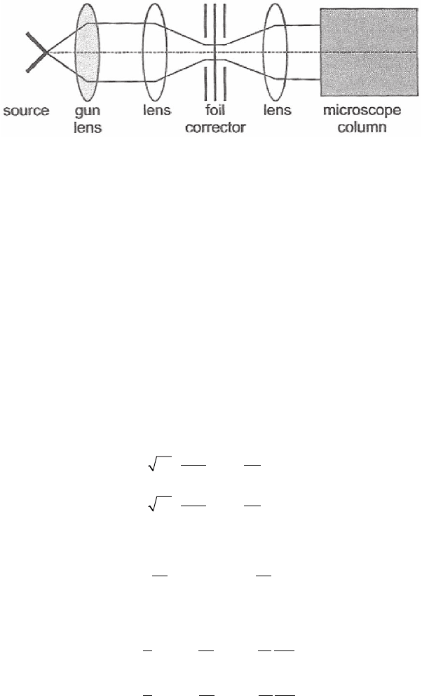
discontinuity in the electric fi eld, has been very thoroughly explored
by a Japanese group (see Hanai et al., 1986, 1994, 1995, 1998). In the
earlier studies, the lens shown in Figure 10–9 was fi tted in a TEM and
was shown to reduce the spherical aberration. Subsequent work has
extended this to probe-forming instruments, notably the STEM, where
again the principle was shown to be valid. The lifetime of the foil was,
however, rather short as a result of the build-up of contamination. For
a recent work using a curved mesh, see Matsuda et al. (2005).
A very different type of foil corrector has been investigated by van
Aken (van Aken et al., 2002a,b, 2004, 2005; van Aken, 2005), who
attempted to exploit the marked increase in the mean free path of
electrons in metal foils at very low voltages. If the latter is atomically
fl at, a mean free path of the order of 5 nm is expected for several metals
Figure 10–9. Foil lens. (a) Schematic cross section of the foil lens. (b) A practi-
cal design, showing the foil lens incorporated in a magnetic objective. (After
Hanai et al., 1998, courtesy of the authors and Oxford University Press.)
a)
b)
718 P.W. Hawkes
at 5 eV above the Fermi level and a transmission of about 10% is pre-
dicted for thin foils (∼5 nm). By sandwiching the foil between a pair of
electrodes, which fi rst retard the incident electrons and then accelerate
them again, correction of both chromatic and spherical aberration is in
principle possible. Figure 10–10 shows schematically a microscope
column incorporating such a corrector.
3.3 Chromatic Aberration Correctors
3.3.1 All-Electrostatic Correctors
One form of the chromatic aberration coeffi cients of a system containing
electrostatic round lens fi elds and electrostatic quadrupole fi elds is
Chhhdz
Chhhd
xxxx
yyyy
c
c
=
′
−
′
′
=
′
−
′
′
∫
φ
φ
φ
φ
φ
φ
φ
φ
0
12
2
0
12
2
1
2
1
2
/
/
()
()zz
∫
(27)
By introducing the Picht transformation,
HhHh
xxyy
=
=
φ
φ
φ
φ
0
14
0
14//
, (28)
these take the form
CHHHdz
CH
xxx x
yy
c
c
=
′
−
′
−
′
=
′
−
∫
φ
φ
φ
φ
φ
φ
φ
φ
0
2
2
2
2
0
1
2
1
16
1
′′
−
′
∫
φ
φ
φ
φ2
1
16
2
2
2
2
HHdz
yy
(29)
If the quadratic term could be reduced to zero (or at least made smaller
than the absolute value of the negative term), the overall chromatic aber-
ration coeffi cient would be negative and the device would hence be suit-
able for use as a corrector. The quadratic term vanishes if the fi eld
distribution is such that the paraxial ray H
x
(z) = Cφ
1/2
and similarly for
H
y
(z), where C is an arbitrary constant. In general, this is not an accept-
able form for H
x
(z) and H
y
(z), which must vanish in the object (and
Figure 10–10. The van Aken low-energy foil corrector. Electrons are slowed
down to a very low energy before passing through the correcting foil and then
accelelerated again before entering the microscope column. (After van Aken,
2005, courtesy of the author.)

Chapter 10 Aberration Correction 719
image) planes. If, however, the corrector is telescopic, such a form is
permissible. By substituting this expression for H
x
(z) and H
y
(z), and
hence h
x
(z) and h
y
(z), back into the paraxial equation, it is trivial to show
that the fi eld functions φ(z) and p
2
(z) must be related by the formula
p
2
2
8
=
′′
−
′
φ
φ
φ
(30)
Confi gurations in which this condition (Scherzer, 1947) is closely
satisfi ed have been found by Weißbäcker and Rose (2000, 2001, 2002)
and by Maas and co-workers (Maas et al., 2000, 2001, 2003; Henstra and
Krijn, 2000). In the studies of Weißbäcker and Rose, several confi gura-
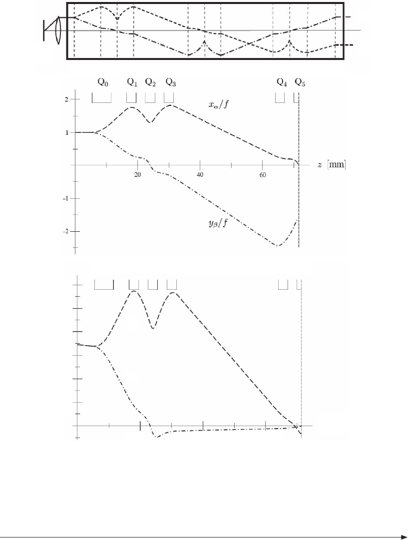
tions are examined, in which the complexity increases with the practi-
cal usefulness of the corrector. In the simplest design, four distinct
elements are employed and the corrector is capable of correcting both
the chromatic and the spherical aberration in a scanning instrument.
The fi rst element is a quadrupole, the purpose of which is to render
the incoming beam astigmatic. This is followed by a three-element
corrector consisting of quadrupole fi elds superimposed on a (round)
einzel lens fi eld. A second corrector unit cancels the chromatic aberra-
tion in the other plane. Octopoles are incorporated so that the spherical
aberration can be corrected simultaneously.
Unfortunately, such a corrector introduces large off-axis aberrations
and is hence not suitable for use with transmission (fi xed-beam) elec-
tron microscopes. Weißbäcker and Rose therefore consider fi rst an
extended version in which a third such element is added (Figure 10–11)
and then propose a doubly-symmetric electrostatic corrector (DECO),
in which each correcting element is enclosed within two quadrupole
doublets (Figure 10–12). The symmetry conditions can now be arranged
in such a way that the chromatic aberration and the coma vanish,
while the spherical aberration is corrected by means of octopoles as
usual.
In the complementary investigations of Henstra, Maas, Mentink, and
co-workers, a confi guration consisting of nine elements (Figure 10–13)
is explored. At the outer extremities are quadrupoles to create astig-
matism and subsequently annihilate it. In the center are fi ve combined
round lens and quadrupole units. Two other quadrupoles are included
to match the slowly decaying round lens fi eld of the fi rst and last com-
bined elements. For further work on this approach, see Baranova et al.
(2004).
3.3.2 Mixed Quadrupole Correctors
Quadrupole lenses consisting of four electrodes and four magnetic
poles situated midway between the electrodes have the power of cor-
recting the chromatic aberration of a round lens. They must of course
be part of a suitable confi guration and are currently incorporated in
the complex superaplanator and ultracorrector described in Section 3.4.
Such correctors have not been seriously considered for correction of C
c
in the transmission electron microscope in recent years, for the simpler
confi gurations increased the spherical (and other) aberrations unrea-
sonably. However, they have been reconsidered recently (Haider and
720 P.W. Hawkes
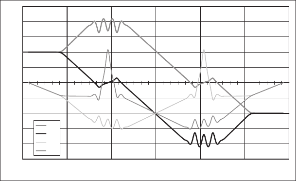
Figure 10–11. Aplanatic corrector of spherical and chromatic aberration. (a) A three-element corrector,
in which the fi rst and third elements cancel the chromatic aberration in the x–z plane while the central
element cancels it in the y–z plane. (b) Axial rays in the fi rst half of the corrector. (c) Field rays in the
fi rst half of the corrector. (After Weißbäcker and Rose, 2002, courtesy of the authors and Oxford Uni-
versity Press.)
Q
0
Q
1
Q
2
Q
3
Q
4
Q
5
x
γ
y
δ
20 40 60
z [mm]
5
10
15
20
25
30
z
0
z
0
z
1
z
m
z
M
z
3
z
4
z
5
z
6
z
7
x
a
y
b
z
8
z
E
l
0
l
1
a)
b)
c)
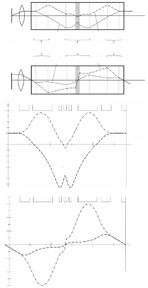
Figure 10–12. Doubly symmetric electrostatic corrector (DECO) of spherical and chromatic aberra-
tion. (a) Axial and fi eld rays in one-half of the DECO; each half consists of a corrector enclosed between
quadupole doublets. (b) Details of the axial rays in one unit of the DECO. (c) Details of the fi eld rays
in the fi rst half of the DECO. (After Weißbäcker and Rose, 2002, courtesy of the authors and Oxford
University Press.)
Chapter 10 Aberration Correction 721
entrance
objective-
lens
object
doublet
correcting element
exit doublet
x
g
y
d
x
a
/ f
y
b
/ f
Q
n
Q
0
Q
1
Q
2
Q
1
Q
0
Q
α
/ f
y
β
/ f
Q
n
z
M
z [mm]
50
0
–1
–2
–3
1
2
3
100
Q
n
Q
0
Q
1
Q
2
Q
1
Q
0
x
g
y
d
Q
n
z
M
z [mm]
50
–2
–4
–6
2
4
6
100
aii)
b)
c)
ai)
722 P.W. Hawkes
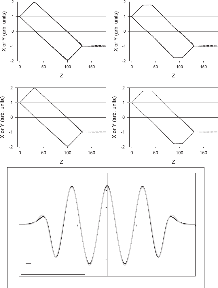
Figure 10–13. Electrostatic correction of chromatic aberration. (a) Rays in a quadrupole quadruplet
or sextuplet. (b) Match between the potentials needed to satisfy Scherzer’s condition and those in the
corrector. (See color plate.)
-3E+08
-2E+08
-1E+08
0E+00
1E+08
2E+08
3E+08
-15 -10 -5 0 5 10 15
Z [mm]
Quadrupole field [V/m/m]
Scherzer's condition
3D Quadrupole
a)
b)
Chapter 10 Aberration Correction 723
Müller, 2004), for there exist more elaborate arrangements that do not
have this handicap. Details are not available as yet.
3.3.3 Wien Filters and Correction
In an attempt to design a corrector that is reasonably easy to align and
consists of as few separate elements as possible, Rose (1990) has exam-
ined the properties of an inhomogeneous Wien fi lter. If such a fi lter is
to correct chromatic aberration instead of acting as a highly dispersive
device, it must be nondispersive, double focusing, and free of all second
rank aberrations (apart from the desired rotationally symmetric chro-
matic aberration). We have seen in other electron optical confi gurations
how useful symmetry and antisymmetry are to eliminate certain aber-
rations. Here, all geometric second-order aberrations can be excluded
by ensuring that the fundamental rays are antisymmetric with respect
to the mid-plane of the fi lter or to the mid-plane of the fi rst or second
half of the fi lter. Rose’s extremely complete study shows that a confi gu-
ration can be found that will correct chromatic aberration. Further-
more, by adding sextupoles before and after the corrector (Figure
10–14), axial chromatic aberration and spherical aberration can be cor-
rected independently.
This idea has been revived by Mentink et al. (1999) and Steffen et al.
(2000), who were seeking further simplifi cation and reduction of the
number of optical elements and excitations. Rose’s device consisted of
a relatively long combined multipole (octopole or dodecapole) with
both magnetic and electrostatic components (as in all Wien fi lters) for
chromatic correction, with external sextupoles. In this new design,
chromatic correction is achieved by means of the usual magnetic and
electrostatic fi elds of the Wien fi lter onto which an electrostatic quad-
Figure 10–13. Continued (c) Gaussian rays in the sextuplet after correcting elements have been placed
at the line foci. The chromatic aberration has been corrected and the residual chromatic aberration of
magnifi cation is small. (After Maas et al., 2001, 2003, courtesy of the authors, SPIE, and the Microscopy
Society of America.)
-2.5
-2
-1.5
-1
-0.5
0
0.5
1
1.5
2
2.5
-90 -60 -30 0 30 60 90
Z [mm]
X or Y (arb. units)
XA
YA
XB
YB
c)
724 P.W. Hawkes
rupole is superimposed. No other magnetic fi elds are required. Spheri-
cal aberration is corrected by superimposing sextupole fi elds, which
are of opposite sign in the fi rst and second halves of the Wien fi lter
zone. Unwanted aberrations are introduced by the fringing fi elds at the
extremities of the corrector but it should be possible to control them by
shaping the ends of the electrodes and magnetic poles.
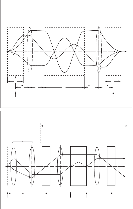
Figure 10–14. (a) Wien fi lter fl anked by two sextupoles and the necessary
transfer lenses, capable of correcting both chromatic and spherical aberration.
The nodal points N and N
–
coincide with the coma-free points. (b) The corrector
in conjunction with a coma-free objective. (After Rose, 1990, courtesy of the
author and the Wissenschaftliche Verlagsgesellschaft.)
sextupole 1
transfer
lens 1
achromator
transfer
lens 2
sextupole 2
h
N
h
f
1
f
2
=
f
1
f
2
=
f
1
f
1
l
U
βδ
–U
δδ
z
U
ββ
N
OA O
1
A
1
W
x
O
2
Z
O
Z
O
4
A
4
corrector
object
plane
objective
double lens
sextu-
pole 1
transfer
lens 1
achro-
mator
transfer
lens 2
sextu-
pole 2
axial
ray
field
ray
b)
a)
