Hawkes P.W., Spence J.C.H. (Eds.) Science of Microscopy. V.1 and 2
Подождите немного. Документ загружается.

1212 J.C.H. Spence
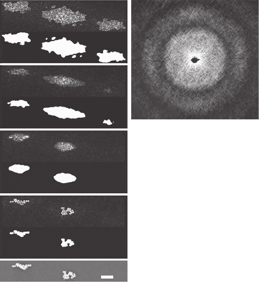
Figure 19–2A shows a transmission diffraction pattern obtained
using 600-eV monochromatic soft X-rays from clusters of gold balls,
50 nm in diameter, lying on a silicon nitride membrane. The silicon
nitride membrane is almost transparent to the X-rays, so the object
provides a useful test object for reconstruction. The pattern resembles
the Airey’s disk-like pattern from one ball, crossed by “speckle” fringes
due to interference between different balls. An image reconstruction
series using the shrinkwrap algorithm, in which the HIO algorithm
A
B
a
b
c
d
e
Figure 19–2. (A) Soft X-ray transmission dif-
fraction pattern from clusters of 50-nm gold
balls lying on a silicon nitride membrane. The
X-ray wavelength is 2 nm (600 eV). The resolu-
tion at the midpoint of the sides corresponds to
a spatial periodicity u
−1
= 17.4 nm, or a Rayleigh
resolution of 8.7 nm. (B) Image reconstruction
series using the shrinkwrap algorithm, in which
the HIO algorithm refi nes the support during
iterations. The top image (a) is the centrosym-
metric autocorrelation function, with the support
estimate shown as a mask below. Intermediate
iterations lead to a fi nal converged image of gold
ball clusters (e) shown at the bottom. The marker
is 1 µm in length. The inversion symmetry is lost
at (c).
Chapter 19 Diffractive (Lensless) Imaging 1213
refi nes the support during iterations, is shown in Figure 19–2B. The
top image is the centrosymmetric autocorrelation function, with the
support estimate shown as a mask below. This mask was obtained by
Fourier transform of the diffraction pattern intensity (to produce the
autocorrelation function shown), followed by the selection of a contour
corresponding to a certain threshold of intensity. This thresholding
operation is repeated after each HIO-ER iteration cycle, to generate a
new improved estimate of the object support (see Marchesini et al.,
2003b, for details). Intermediate iterations lead to the fi nal converged
image of the gold ball clusters (e) shown at the bottom. The marker is
1 µm in length. We note that the inversion symmetry necessarily pos-
sessed by the autocorrelation function at (a) is lost at (c) as it changes
smoothly into the correctly phased image.
Figure 19–3 shows an instructive case, indicating the way in which
“prepared objects” may be used to assist reconstruction. [Full experi-
mental details for CXDI are given in He et al. (2003), from which Figure
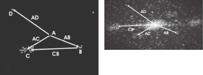
19–3 is taken.] Figure 19–3A shows a scanning electron microscope
(SEM) image of a set of gold balls lying on a silicon nitride membrane.
One ball at A is isolated. The autocorrelation function obtained from
an experimental soft X-ray transmission diffraction pattern (not shown)
taken from this object is given in Figure 19–3B. This may be interpreted
as the self-convolution of the object with its inverse, or, for a collection
of point-like objects, as the set of all interpoint vectors. Some interball
vectors are shown in Figure 19–3A and indicated again in Figure 19–3B.
The convolution of the single isolated ball A with the three balls at B
produces the autocorrelation function in Figure 19–3B a faithful image
of the three balls, blurred by the image of one ball. This process is
A
B
Figure 19–3. (A) SEM image of several clusters of gold balls, each 50 nm in diameter. Some interball
vectors are indicated. The balls lie on an X-ray transparent substrate. (B) The Fourier transform of the
X-ray diffraction pattern taken from (A). This is the autocorrelation function of the density in (A) and
is a map of all interball vectors or the self-convolution of the object with its inverse. Because the object
in (A) includes a single isolated ball at A, the vector AB leads to a faithful image of the triple-ball
cluster at B. (The convolution of one ball with three gives a blurred image of three.) (From He
et al., 2003.)
1214 J.C.H. Spence
similar to the heavy-atom method of X-ray crystallography, or the
method of Fourier transform holography in optics (Collier et al., 1971).
If such a gold ball or strong “point” scatterer can be placed near an
unknown object, the autocorrelation function will contain a useful fi rst
estimate of the desired image of the unknown, which can also be used
to provide a support for further HIO iterations aimed at improving
resolution. This process is demonstrated in He et al. (2004), where, fol-
lowing the original suggestion of Stroke (1997), it is found that the
resolution in the autocorrelation “image” may be considerably improved
beyond the size of the reference ball by simple deconvolution. By using
a larger reference object, or one consisting of a cluster of small balls,
the intensity of scattering from the reference object can be increased.
It has been noted that a randomly placed cluster of point scatterers can
provide a high resolution image in Fourier transform holography when
used as a reference object (see He et al., 2004; Collier et al., 1971; Eisebett
et al., 2004, for more details and references).
The fi rst successful application of CDI to the electron diffraction
patterns provided by a transmission electron microscope (TEM) is
described in Weierstall et al. (2001), where a complete description of
the method can be found. An important asset of the TEM is its ability
to provide an image of the same region that contributes to the micro-
diffraction pattern, so that this image can be used to supply the support.
However, electron scattering is so strong that any scattering contribu-
tion from a supporting fi lm, however thin, is found to prevent success-
ful CDI. The resolution of the best TEM instruments in direct
phase-contrast imaging mode using lenses is now about 1 Å. Figure
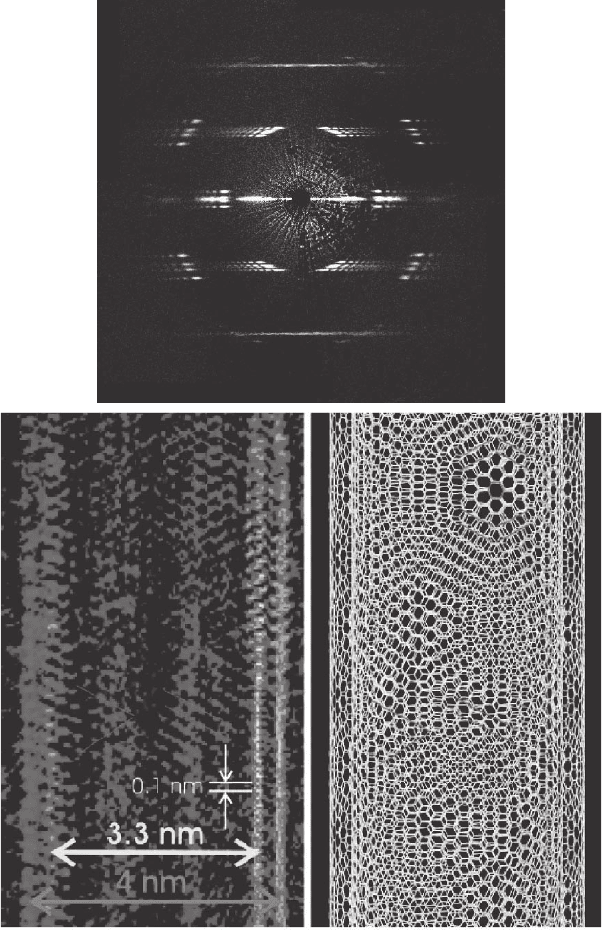
19–4 shows a more recent application of CDI to an electron diffraction
pattern using a TEM (Zuo et al., 2003). This remarkable image is the
fi rst atomic-resolution CDI image, and possibly the fi rst atomic-
resolution image of a nanotube. The image gives us the helicity of the
tube, its dimensions, and the number of walls. The double-walled
nanotube spans a hole in a thin amorphous carbon fi lm, while the
electron beam diameter (about 50 nm) is smaller than the hole, so that
there is no background contribution from the carbon fi lm. A conven-
tional TEM image was used to provide the support function for HIO
iterations along the edges of the tube, and it is suggested that the
boundary of the support across the tube is provided by loss of coher-
ence at the edge of the electron probe due to rapid phase variations
arising from the aberrations of the probe-forming lens. (In general a
tight support is desirable for CDI.) The image shows higher resolution
detail than conventional TEM images of nanotubes. Resolution is
limited perhaps only by the temperature factor, or by distortions in
electron lenses used to magnify the diffraction pattern. It remains to
be seen if tomographic imaging at atomic resolution is simplest by this
method or by direct TEM imaging using lenses. If CDI is used, the
diffi cult problem of supporting a nanoparticle for diffraction over a
range of orientations will need to be solved. Radiation damage may be
reduced in diffraction mode under some conditions.
Three-dimensional (tomographic) CDI of inorganic samples has now
been demonstrated (Miao et al., 2002; Williams et al., 2003; Chapman
Chapter 19 Diffractive (Lensless) Imaging 1215
et al., 2006) using soft X-rays at a resolution of about 10 nm. This raises
hopes of direct imaging, for example, of whole cells by this method if
radiation damage considerations allow this at usefully high resolution.
The X-ray source is a synchrotron and undulator, providing coherent
A
B
Figure 19–4. (A) Electron microdiffraction pattern from a single double-
walled nanotube. This consists of a rolled-up sheet of graphite. Fine details
arise from the helical structure (Zuo et al., 2003). (B) At left is the experimental
image of the double-walled nanotube reconstructed from the electron diffrac-
tion pattern in (A). At right is shown a corresponding model of the structure
(Zuo et al., 2003).
1216 J.C.H. Spence
radiation at about 600 eV. In recent work (Chapman et al., 2006), a
simple zone plate was used as a monochromator, following by a beam-
defi ning aperture of about 10 µm in diameter, coherently fi lled. A nude
soft X-ray CCD camera, employing 1024 × 1024 24-µm pixels was used.
The sample is mounted in the center of a silicon nitride window fi tted
to a TEM single-tilt holder, which provides automated rotation about
a single axis normal to the X-ray beam. The window is rectangular,
with the long axis normal to both the beam and the holder axis. Dif-
fraction patterns are recorded at 1° rotation increments, with a typical
recording time of about 15 min per orientation. The maximum tilt angle
is then limited by the thickness of the silicon frame around the window
to perhaps 80°, resulting in a missing wedge of data. In addition, data
may be missing around the axial beamstop. The development of
software for automated tomographic diffraction data collection and
merging is a large undertaking (Frank et al., 1996), and much can be
learned from the prior experience of tomography in biological electron
In that case, however, the registration of successive images at different
tilts is greatly facilitated by direct observation of image features. The
use of shadow images or X-ray zone-plate images for similar purposes
has been suggested. With no direct imaging mode, much time is wasted
in X-ray work locating the beam on the sample, which, with current
CCD detectors, will typically be smaller than 2 µm in diameter. The
fi nal resolution (in one dimension), allowing for an “oversampling”
factor of 2, will then be 4000/1024 = 3.9 nm. The camera length (sample-
to-detector distance) of the diffraction camera must then be selected to
allow half this spatial frequency to fall at the edge of the CCD camera
at u
max
= θ
max
/λ = 0.5/3.9 nm
−1
, so that the maximum scattering angle is
θ
max
= 0.25 rad for λ = 2 nm. Then the fi nest periodicity in the object
(3.9/0.5 nm) is sampled twice in every period, according to Shannon’s
requirement (two points are required to defi ne the period and ampli-
tude of a sine wave if aliasing is excluded). For a CCD with linear pixel
number N, the ratio of the fi nest detail to largest dimension is N/2, so
that developments in detector technology limit CDI. The transverse
spatial coherence of the beam must exceed 4 µm, as discussed together
with monochromator requirements below.
Tomographic or three-dimensional imaging can provide the ability
to “see inside” an object, but this requires that the intensity at a point
in a projection be proportional to a line integral of some simple prop-
erty of the object, such as the charge density. Then methods such as
fi ltered back-projection can reassemble these two-dimensional projec-
tions into a volume density. Contours of equal density may then be
isolated and presented to show the internal structure. For CXDI, a dif-
ferent approach is used, and some simplifi cations occur. It is no longer
necessary to make the resolution-limiting “fl at Ewald sphere” approxi-
mation, since diffraction data collected at one tilt can be assigned to
points lying on the curved Ewald sphere in reciprocal space. (This is
the momentum and energy-conserving sphere that describes elastic
scattering in reciprocal space.) The sample is then rotated through this
sphere around a single axis, until all of the reciprocal space is fi lled,
microscopy, where these techniques have been perfected (Frank, 2006).
Chapter 19 Diffractive (Lensless) Imaging 1217
out to a given resolution. Three-dimensional interpolation of data
points near the sphere is needed, and careful intensity scaling may be
necessary if several exposures with different times are required to
cover the full dynamic range of the data. It is often found that missing
data points in the central region can be treated as adjustable parame-
ters in the HIO iterations. Once a roughly spherical volume has been
fi lled in reciprocal space (perhaps with missing wedge and beam-stop
region), the three-dimensional iterations of the HIO algorithm may be
applied [Eqs. (8), (9), etc., extended to three dimensions]. The comput-
ing demands are severe, as outlined below. The converged data will
provide a three-dimensional density map, proportional to the local
charge density, if the single-scattering approximation of X-ray diffrac-
tion theory applies and if the spatial variation in attenuation of the
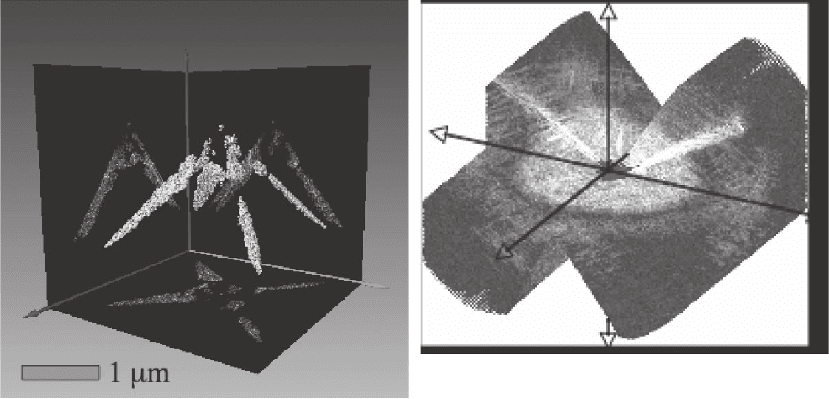
beam due to the photoelectric effect can be neglected. Figure 19–5
shows such a tomographic reconstruction, from which three-dimen-
sional surfaces of constant density may be obtained. These surfaces
allow us to “see inside” materials, and may eventually permit maps
to be obtained that distinguish regions of different chemical
composition.
The usefulness of tomographic CXDI in biology remains to be deter-
mined; at present the method appears to have the advantages over
electron microscopy by allowing observation of thicker samples under
a wider range of environments (for example, in the “water window”
around 580 eV for soft X-rays). By comparison with X-ray zone-plate
“full-fi eld” imaging, the method allows a much larger numerical aper-
ture to be used, and hence makes more effi cient use of scattered
A
B
Figure 19–5. (A) Tomographic reconstruction from a soft X-ray diffraction pattern shown in (B). The
object consists of gold balls (50 nm diameter) lying along the edges of a pyramidal-shaped silicon
nitride structure. This is one image from a rotation series. From the complete series, three-dimensional
surfaces of constant density can be constructed. (B) The volume of soft X-ray diffraction data collected
to obtain the three-dimensional reconstruction in (A). (See color plate.)
1218 J.C.H. Spence
photons, while providing potentially higher resolution. At high resolu-
tion the depth of focus λ/θ
2
may become less than the sample thick-
ness, which prevents tomographic reconstruction by back-projection
methods based on simple projections. Then tomography may best be
undertaken using optical sectioning rather than reconstruction from
projections. CDI, based on three-dimensional diffraction data, pro-
vides a third alternative. The resolution limit imposed by radiation
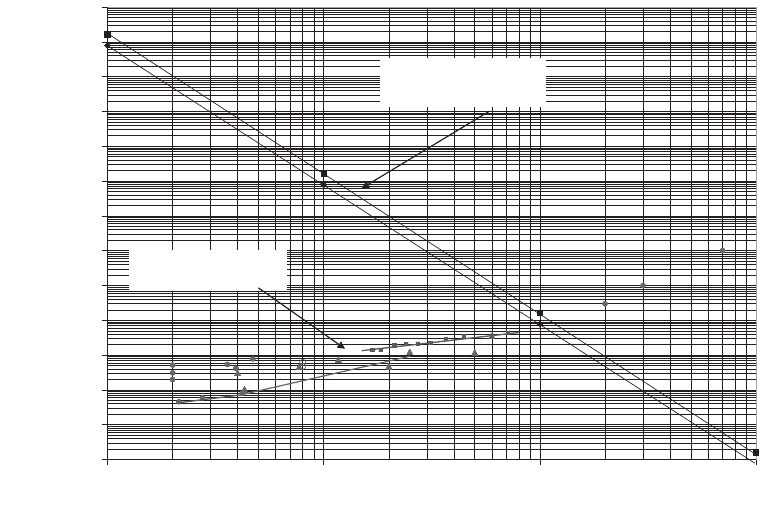
damage in CXDI, as expressed by the Rose equation (Spence, 2003),
remains to be determined experimentally, but is likely to be signifi -
cantly poorer than 1 nm, which has already been achieved in three-
dimensional single-particle electron microscopy of proteins. Howells
et al. (2005) and Marchesini et al. (2003a) provide a detailed discussion
of this large subject, including a plot of dose against resolution for
various microscopies in biology, as discussed in Section 9, shown in
1.0E+05
1.0E+06
1.0E+07
1.0E+08
1.0E+09
1.0E+10
1.0E+11
1.0E+12
1.0E+13
1.0E+14
1.0E+15
1.0E+16
1.0E+17
1.0E+18
0.1 1 10 100
Resolution (Å)
Dose(Gy)
(ROSECRITERION)
MAXIMUM TOLERABLE
DOSE
REQUIRED IMAGING DOSE
Figure 19–6. Summary of experimental measurement on organics for various microscopies on a plot
of dose against resolution (Howells et al., 2005). Literature experimental values (e.g., Reimer, 1989) are
shown as follows: Filled circles are from X-ray crystallography, fi lled triangles from electron crystal-
lography, open circles from single-particle electron cryoelectron microscopy, open triangles from
electron tomography, diamonds from soft X-ray microscopy, and fi lled squares from recent X-ray
crystallography work on spot-fading experiments by Holton on the ribosome at the Advanced Light
Source. Viable single-molecule microscopies must fall above the Rose equation line (to give a statisti-
cally signifi cant image) and below the maximum tolerable damage line. Those below the Rose equation
line succeeded by using crystallographic redundancy and form a periodically averaged image of
perhaps 10
8
molecules in a crystal. The required imaging dose is calculated for a protein of empirical
formula H50C30N9O10S1 and density 1.35 g/cm
3
against a background of water, imaged with 10 keV
X-rays (upper Rose line) and 1 keV (lower Rose line).
Chapter 19 Diffractive (Lensless) Imaging 1219
Figure 19–6 (see also Henderson, 1995). The dose-fractionation theorem
of Hegel and Hoppe is also relevant (Reimer, 1989). Recently, dramatic
images of whole yeast cells have been imaged by CDI (Shapiro et al.,
2005) using the apparatus described by Beetz et al. (2005).
6 Iterated Projections
A breakthrough in understanding the remarkable success of the HIO
algorithm occurred in 1984, when Levi and Stark (1984) (based on
earlier work by Youla and Webb, 1982) showed that the algorithm could
be understood as successive Bregman projections between convex and
nonconvex sets. Here an image is represented as a single vector R in
an N-dimensional space, with one coordinate for each pixel. The addi-
tion of two such vectors adds together two images. Distance between
images (vectors) in this space has the form of the familiar χ
2
goodness
of fi t index, so that similar images are near each other. The set of all
images subject to a given constraint (e.g., known symmetry, known
Fourier modulus, known sign of density, known support) is considered
to occupy a volume in this space. The operation of taking a current
estimate of the image, performing a Fourier transform, replacing the
magnitudes of the diffracted amplitudes with the measured values,
and inverse transforming was shown to be a projection onto the set of
images subject to the Fourier modulus constraint. Vectors R between
the boundaries of two constrained sets of images are considered. If it
is shown that all the images within the only overlap between two
constrained sets are equivalent solutions, then the phase problem
reduces to fi nding this volume, where R = χ
2
and the ER error metric
are a minimum. Constraints may be of two types—convex and non-
convex. For a convex set, all points on any line segment terminating
within the set lie inside the set. A set P is convex if αR + (1 − α)R′ lies
within P for all R and R′. Here 0 < α < 1 is a scalar defi ning position
along the line. In two dimensions, a kidney-shaped set is nonconvex
and an ellipse is convex. Bregman has shown that iterative projections
between convex sets must lead directly to a unique solution if it exists,
without stagnation. In this manner the global optimization problem is
solved without an exhaustive search for the case in which a unique
solution and convex constraints are known to exist. For our problem
the Fourier modulus constraint (the known diffraction intensities) is
nonconvex, so that this approach has been of limited value. However,
it provides a powerful geometric way of thinking about the algorithm
as a trajectory in Hilbert space, which is usually drawn in two dimen-
sions for simplicity. The effects of variations in feedback parameter β
can be understood, convergence properties studied, and new algo-
rithms proposed. For the ER algorithm, the path is a zig-zag between
the boundaries of sets; for the HIO it is a spiral. Some desirable convex
constraints include known support, a knowledge of phase rather than
amplitude, the sign constraint, symmetry, a known histogram of
density levels (Zhang and Main, 1990) (such as exists for proteins),
1220 J.C.H. Spence
entropy minimization, and (for nonoverlapping atoms) atomicity. A list
of constraints used in protein crystallography can be found in the rel-
evant section of volume F of the international tables on crystallography.
Application of these constraints thus avoids the common problem
whereby optimization programs become trapped in local minima.
The application of constraints can be viewed as projections in the
N-dimensional space. Recall that the support S is defi ned as the set of
points for which the density is nonzero. For example, application of the
support constraint P
s
corresponds to setting many pixels to zero, that
is, to projecting onto a space of lower dimension. For the Fourier
modulus constraint, we note that Parseval’s theorem ensures that dis-
tances in the N-dimensional real space are equal to those in a similar
N-dimensional space of Fourier coeffi cients. Consider an Argand
diagram for a particular Fourier component, for which the modulus
constraint restricts solutions to a circle, whose radius is given by the
measured value of the Fourier modulus. An estimate provided by the
algorithm (e.g., outside this circle) must be projected (by operator P
m
)
onto the nearest point on the circle, along a line that will pass through
the origin. (This corresponds to the numerical process during one itera-
tion of retaining the current phase estimate, but replacing the magni-
tude with the measured magnitude, in the HIO algorithm.) Since the
linear addition of two vectors terminating on the circle does not
produce a third that terminates on the circle, the modulus constraint
is not convex. Note, however, that the addition of two vectors of arbi-
trary length but equal phase produces a new complex number with the
same phase, so that a knowledge of phase is a convex constraint, and
thus more powerful than a knowledge of amplitudes. The identity
operation I is also useful, and a refl ector operation R
s
= 2P
s
− I can be
defi ned, which reverses the sign of the density outside the support S.
Using these operators, all the iterative algorithms can be represented
simply and analyzed as alternating projections onto convex (and non-
convex) sets (POCS). In this context, we may defi ne these more limited
projections as “projectors,” which takes a given vector R to the nearest
point of a nearby constrained set (usually on its boundary). Then
1. The error-reduction (ER) (Gerchberg–Saxton) algorithm may be
written
ρ
(n+1)
= P
s
P
m
ρ
(n)
2. The charge-fl ipping (CF) algorithm may be written
ρ
(n+1)
= R
s
P
m
ρ
(n)
3. The hybrid input–output (HIO) algorithm may be written
ρ
(n+1)
(r) = P
m
ρ
(n)
(r) if r ∈ S
ρ
(n+1)
(r) = (I − β)P
m
ρ
(n)
(r) if r ∉ S
4. The averaged successive refl ections (ASR) algorithm may be
written
ρ
(n+1)
= 0.5(R
s
R
m
+ I)ρ
(n)
Chapter 19 Diffractive (Lensless) Imaging 1221
Similar descriptions of the difference map method (Elser, 2003), the
hybrid projection refl ection (HPR) (Bauschke et al., 2002), and the
relaxed averaged alternating refl ectors (RAAR) (Luke, 2005) have been
given. For β = 1, the HIO, HPR, ASR, and RAAR algorithms are identi-
cal. A comparison of the performance of all of these, together with the
powerful shrinkwrap algorithm (HIO with dynamic support) and
simple geometric representations of the trajectory of the error metric
for few-dimensional cases, can be found in Marchesini (2006).
Using this approach, it has also been shown that the HIO algorithm
is equivalent to the Douglas–Rachford algorithm, and is related to clas-
sical convex optimization methods (Bauschke et al., 2002). The text by
Stark (1987) is recommended as a tutorial introduction to this large
subject.
7 Coherence Requirements for CDI: Resolution
It is readily shown (Spence et al., 2004) that the lateral or spatial coher-
ence requirement for diffractive imaging is, in one dimension, that the
coherence width X
c
∼ λ/θ
c
be at least equal to twice the largest lateral
dimension W of the object. (This is similar to the requirement in crys-
tallography that X
c
exceed the dimensions of a primitive unit cell to
avoid overlap of Bragg beams, with beam divergence θ
c
. For phasing
by the oversampling method, this cell must be about twice as large as
the molecule.) This fi xes the incident beam divergence and hence the
exposure time for a given object size and source. Since at the unaper-
tured diffraction limit (Θ = 90°) the resolution is approximately equal
to the wavelength and about two pixels are required per resolution
element, a total of about (4X
c
/λ)
2
image pixels would be needed for a
coherence width X
c
and oversampling factor 2. Physically, this just
means that the coherence patch must include the “known” region of
vacuum (zero density) surrounding the object boundary (support). It
is necessary to diffract coherently from an area twice as large as the
isolated object of interest.
The temporal coherence length L
c
is also important. For a fi eld of
view W at the object (so that the fi rst oversampling point occurs at
scattering angle λ/W) and fi nest (bandlimited) object spatial frequency
d
−1
, the optical path difference between points on opposite sides of the
object and a distant detector point is W sin θ = Wλ/d, which should not
exceed the longitudinal coherence length for X-rays L
c
= λE/∆E. Hence
the fractional energy spread allowable in the beam to record spatial
frequency d
−1
is E/∆E > W/d = N, where d is the sampling interval
in the object and N the linear number of pixels needed to sample
the object space in the HIO algorithm. A more detailed calculation,
considering the shape of the temporal coherence function, gives the
requirement on longitudinal coherence as about E/∆E > N/3, which
improves on the estimate in Spence et al. (2004). This determines the
quality of the monochromator needed. In practice values of E/∆E = 500
have yielded good results in soft X-ray work using CCD detectors with
N
2
pixels, where N = 1024. Then the in-line arrangement of a simple
