Gasch R., Twele J. (Eds.) Wind Power Plants: Fundamentals, Design, Construction and Operation
Подождите немного. Документ загружается.

8.2 Free and forced vibrations of wind turbines - examples and phenomenology
292
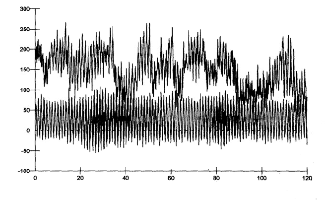
energy strongly excites the first flapwise natural frequency of the blade. The
response of the edgewise bending moment is shown as well. It is more narrow-
banded and is above all dominated by the alternating bending with the rotational
frequency induced by the blade weight. Here, the gustiness of the wind has only a
small influence.
Flapwise bending
Edgewise bending
Time in s
Bending moment at the root of the blade in kNm
Flapwise bending
Edgewise bending
Time in s
Bending moment at the root of the blade in kNm
Fig. 8-16 Simulated response of the flapwise and edgewise bending moment at the blade root
due to stochastic excitation by the wind, wind turbine of 500 kW
8.2.3 Drive train vibrations
In essence, the excitations of the vibrations in the drive train stem from:
- the blade passage: number of blades times the rotational frequency and its
harmonics,
- the turbulent wind field,
- the vertical wind profile for one- and two-bladed wind turbines,
- action of the control, blade pitching, torque moment changes in the
generator,
- teeth contact frequencies,
- etc..
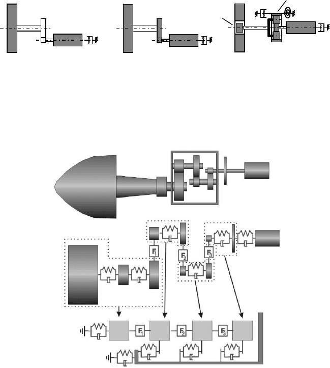
The sufficient treatment of the dynamics of torsion of smaller wind turbines
(D < 50 m) is possible by modelling the drive train as a system with 2 or 3 degrees
of freedom (DOF), Fig. 8-17 left and middle. However, magnetic forces act
between rotor and stator of the generator which may be modelled for a synchronous
8 Structural dynamics
293
generator a as load dependent torsional spring. The forces for an asynchronous
generator, which has a slip to the grid frequency, may be described by a torsional
damper, as shown in Fig. 8-17, where the damping coefficient results from the
slope of the torque characteristic at the synchronous frequency, cf. chapter 11. For
large wind turbines the first edgewise eigenmode of the blades has to be consid-
ered in the dynamics of torsion and the fact that the casing of the gearbox is
mounted on the nacelle frame in elastic rubber bushings. Thus, one more degree of
freedom comes into play, and the drive train has four degrees of freedom - possi-
bly even five if individual inertia is assigned to the gear wheels in the model, Fig.
8-17, right.
Ĭ
Rotor
Ĭ
Gen
c
1
c
2
i
Gear
2 DOF
3 DOF
Ĭ
Hub
Ĭ
3Blade
Ĭ
Housing
5 DOF
Ĭ
Rotor
Ĭ
Gen
c
1
c
2
i
Gear
2 DOF
3 DOF
Ĭ
Hub
Ĭ
3Blade
Ĭ
Housing
5 DOF
Fig. 8-17 Modelling of the torsional drive train dynamics with different numbers of degrees of
freedom (in grey: moment of inertia Ĭ; torsional stiffnesses c
1
, c
2
, etc.; spring and damping
systems from the gearbox housing and generator)
Fig. 8-18 Modelling of the drive train dynamics as a multi-body system [10]
8.2 Free and forced vibrations of wind turbines - examples and phenomenology
294
Recent studies on the three-dimensional situation of the loading at the hub and in
the entire drive train as well as the damages observed in reality with larger wind
turbines show clearly the limitations and the inadequacies of the models described
above. As a result, multi-body-system models are being developed. Fig. 8-18
shows a model with torsional and translational degrees of freedom [10]. These
investigations become very complex if the gaps between the teeth flanks and,
moreover, the elasticities of the support provided by the nacelle frame and the
tower are considered.
The drive train is only slightly damped from the mechanical and aerodynamic
side. The edgewise movement of the blades merely provides an aerodynamic tor-
sional damping (see below). Only the elastic rubber support of the casing has a
positive effect – if a suitable rubber material is chosen. Fortunately, in modern
variable-speed wind turbines stability problems of the drive train may be avoided
by introducing torsional damping artificially via the generator: the air gap
moments can be varied by the fast electrical torque control of the generator.
8.2.4 Sub-models - overall system
For dynamic investigations at an early design stage it is advisable to cut the over-
all system of a wind turbine into suitably selected sub-systems, e.g.
- The tower-nacelle system with rigid blades
- The blade rigidly clamped at the root
- The drive train (dynamics of torsion), etc.
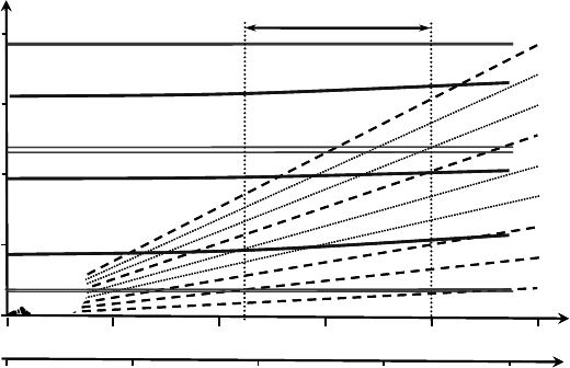
Drawing the natural frequencies of the sub-systems in their dependency on the
rotational speed in one single Campbell diagram, Fig. 8-19, allows us not only to
detect potential resonance problems but also to judge the danger of interference of
natural frequencies which lie close together.
Changes in the natural frequencies also occur if eigenmodes of the sub-systems
influence one another. The example of the drive train dynamics shows that espe-
cially for large wind turbines the simplified consideration of the blades as rigid
bodies is inadmissible. Here, the blade’s first edgewise natural frequency is that
low that it falls into the range of the drive train’s first torsional natural frequency
at which the rotor of the turbine oscillates against the generator. Thus a coupling is
formed: blade and drive train dynamics are married inseparably together. Some
vibration modes are even influenced by the tower dynamics. Therefore, the natural
frequencies determined for the sub-systems are shifted in the assembled overall
system.
8 Structural dynamics
295
Operating range
510 1520 25
Rotational speed
in rpm
1
st
Tower
bending
1
st
Flapw.
bending
1
st
Edgewise
bending
1
st
Tower torsion
2
nd
Flapwise bending
2
nd
Tower bending
Longitudinal
Lateral
1
2
3
4
Natural and rotational
frequency in Hz
1ȍ
2ȍ
3ȍ
4ȍ
5ȍ
6ȍ
7ȍ
8ȍ
9ȍ
0
0.1 0.2 0.3 0.4
0
in Hz
Operating range
510 1520 25
Rotational speed
in rpm
1
st
Tower
bending
1
st
Flapw.
bending
1
st
Edgewise
bending
1
st
Tower torsion
2
nd
Flapwise bending
2
nd
Tower bending
Longitudinal
Lateral
1
2
3
4
Natural and rotational
frequency in Hz
1ȍ
2ȍ
3ȍ
4ȍ
5ȍ
6ȍ
7ȍ
8ȍ
9ȍ
0
0.1 0.2 0.3 0.4
0
in Hz
Fig. 8-19 Campbell diagram with natural frequencies of the tower-nacelle system and the cou-
pled blade – drive train system of a typical 1.5 MW wind turbine with variable rotational speed
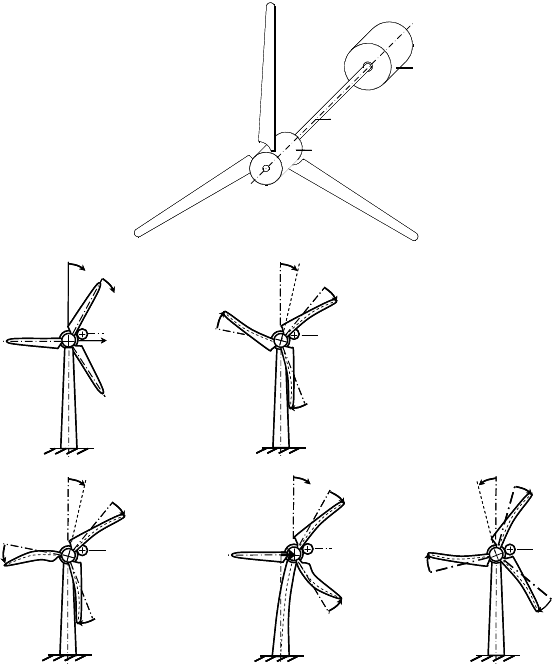
Fig. 8-20 top shows a simplified drive train model, where the blades are elastic. In
eigenmode I the blades and the hub oscillate together against the generator. In
eigenmode II, which is sometimes called lambda-eigenmode due to its
O
-shape, two
blades bend together in the edgewise direction and the third blade balances them
with doubled amplitude. Eigenmode III is characterised by two blades vibrating
against each other while the third stays calm (Y or tuning fork eigenmode).
Eigenmodes II and III are not coupled with the drive train torsion. The bending
moments at the hub are balanced. The corresponding natural frequencies are
(nearly) similar to the natural frequencies obtained for a rigid clamping of the
blade. However, with eigenmode III the tower shows a small accompanying
motion. In eigenmode IV the blades retain the packet-shaped vibration of Eigen-
mode I, but now the body of the hub vibrates in opposition to the blades. Since in
the model we allowed five degrees of freedom (for each blade an individual
edgewise degree of freedom, plus one for the hub-gearbox unit and one degree of
freedom for the generator) there is one natural frequency and eigenmode missing:
it is the “rigid-body degree of freedom”, the free unbound rotation of the entire
drive train which has the natural frequency of zero.
8.2 Free and forced vibrations of wind turbines - examples and phenomenology
296
Rotor (mit Getriebe)
Torsionsfeder
Generator
Torsion spring
Rotor (and gear box)
Rotor (mit Getriebe)
Torsionsfeder
Generator
Torsion spring
Rotor (and gear box)
0
ij
B
l
a
d
e
˳
Hub
+1
+1
+1
+1
+1
-2
+1
-1
0
0
+1
+1
+1
u
Nacelle
Mode II
Mode III
Mode IV
Mode I
0
0
+
0
ij
B
l
a
d
e
˳
Hub
+1
+1
+1
+1
+1
-2
+1
-1
0
0
+1
+1
+1
u
Nacelle
Mode II
Mode III
Mode IV
Mode I
0
0
+
Fig. 8-20 Eigenmodes of coupled blade-drive train system, eigenmodes I, II and IV coupled
with the drive train torsion, mode III coupled with the lateral nacelle vibration
1ȍ-Shift
Another typical effect in the overall system is the 1ȍ-shift. Mass unbalances as
well as an aerodynamic unbalance (blade angle or twist angle deviations) excite
vibration of the tower head with the frequency 1ȍ equal to the rotational fre-
quency in the lateral direction of the nacelle, see section 8.2.1.
These lateral vibrations of the nacelle act in the rotating system as a 2ȍ base
excitation (with twice the rotational speed) of the rotor blades in the edgewise di-
rection [11]. If the first two natural frequencies of the blades are close to double
or triple the maximum rotor speed, resonance problems may be provoked. This
1ȍ-shift is familiar to us already from gravitational influences: considered in the
8 Structural dynamics
297
inertial system without rotation, 0ȍ, the gravity force acts constantly on the
blades, whereas in the rotating system it acts periodically with the rotational fre-
quency 1ȍ. Therefore, in the resonance diagram of a three-bladed wind turbine,
Fig. 8-19, not only are the beams of the 1ȍ-, 3ȍ-, 6ȍ-, etc. excitations shown but
also the one for the 2ȍ excitation.
Simulation of the overall system dynamics
For larger wind turbines in the early design stages a model for the overall system
dynamics is developed, which considers all the couplings between the sub-
systems. It also comprises the electrical and electro-mechanical (or hydraulic)
degrees of freedom of the control and controllers. The solution of these “equations
of motion” is then calculated in the time domain by digital simulation. Compared
to the consideration in the frequency domain this has the advantage that even non-
linearities and transient processes may easily be considered. Section 8.3 gives an
introduction to the common procedures.
8.2 .5 Instabilities and further aeroelastic problems
Aeroelastic instabilities
In the discussion of the shut-down of a wind turbine we saw how slowly the
natural vibrations of the tower-nacelle system decay, Fig. 8-11, since in this case
there are only small damping forces from the flange connections of the tower and
from the soil.
However, if the machine operates close to the design tip speed ratio, the nacelle
vibrations in the axial direction and the blade vibrations in the flapwise direction
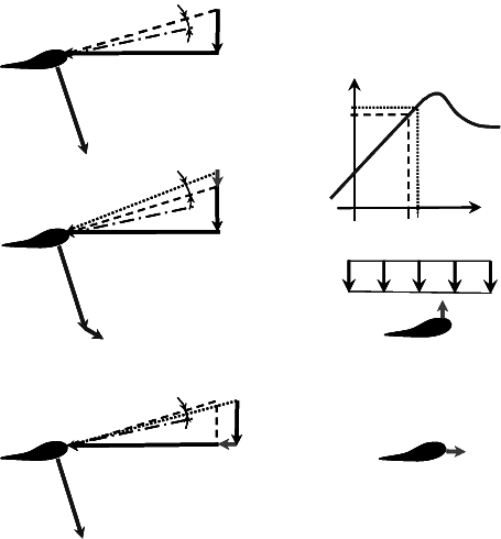
are well damped by aerodynamic forces. Fig. 8-21 shows in the middle how a
(flapwise) movement of the blade against the wind direction changes the triangle
of velocity. An additional lift ǻdL is produced which acts against this movement,
i.e. damps it. However, it also becomes clear that if the wind turbine operates in
the region of separated flow (i.e. stall) which is found to the right of the maximum
of the lift curve c
A
(
D
A
) then the deviation c
A
´ of the lift coefficient changes its
sign. The additional lift ǻdL produced by the flapwise movement becomes nega-
tive which means that vibrations are “fuelled” by the reduced damping. If there is
insufficient “structural damping” then the natural vibrations increase and instabil-
ity occurs. Of course, in the stall region the drag forces from c
D
have to be con-
sidered as well, so this case again becomes a little more complicated [12, 13].
8.2 Free and forced vibrations of wind turbines - examples and phenomenology
298
The edgewise movements of the blade provide only very small aerodynamic
damping, which may be concluded from Fig. 8-21 (bottom). Since the circumfer-
ential speed u is much bigger than the wind speed v
2
in the plane of rotation, the
aerodynamic forces – and above all the angle of attack
D
A
- merely change if
edgewise movements occur. The additional edgewise velocity 'u
edge
is small
compared to the circumferential speed u, consequently vibration modes where the
edgewise movement dominates are merely damped and therefore imply the danger
of instability. Therefore, there are sometimes dampers for the edgewise move-
ments installed in the blade tips of stall-controlled wind turbines (e.g. LM blades).
dA
c
Į
A
u
v
2
ǻv
Flap
ǻu
Edge
ǻdA < 0
v
2
ǻ
Į
A
< 0
ǻu
Edge
Į
A
c
A
v
2
ǻv
Flap
ǻdA > 0
ǻ
Į
A
>
0
v
2
u
ǻ
Į
A
dA
c
Į
A
u
v
2
ǻv
Flap
ǻu
Edge
ǻdA < 0
v
2
ǻ
Į
A
< 0
ǻu
Edge
Į
A
c
A
v
2
ǻv
Flap
ǻdA > 0
ǻ
Į
A
>0
v
2
u
ǻ
Į
A
c
L
w
dL
'dL > 0
'dL < 0
dA
c
Į
A
u
v
2
ǻv
Flap
ǻu
Edge
ǻdA < 0
v
2
ǻ
Į
A
< 0
ǻu
Edge
Į
A
c
A
v
2
ǻv
Flap
ǻdA > 0
ǻ
Į
A
>0
v
2
u
ǻ
Į
A
dA
c
Į
A
u
v
2
ǻv
Flap
ǻu
Edge
ǻdA < 0
v
2
ǻ
Į
A
< 0
ǻu
Edge
Į
A
c
A
v
2
ǻv
Flap
ǻdA > 0
ǻ
Į
A
>0
v
2
u
ǻ
Į
A
c
L
w
dL
'dL > 0
'dL < 0
Fig. 8-21 Effect of flapwise bending and edgewise bending on the aerodynamic forces, aero-
dynamic damping and negative damping. Reference location (top), flapwise movement (middle),
edgewise movement (bottom)
8 Structural dynamics
299
Further aeroelastic problems
There are further aeroelastic problems which may occur, e.g.
- Stall-induced edgewise vibrations, provoked by flow separation which
may be reduced by dampers close to the blade tip (see above and cf.
chapter 3) [14]
- Unstable torsional drive train vibrations with the strong involvement of
edgewise blade movement and generator (or generator-converter system)
- Vibrations of the blade pitch controller, where the axial vibrations of the
tower-nacelle system (u,
u
) suggest incorrect wind speeds v
2
± u
, instead
of the real wind v
2
. The consequent action of the controller reduces the
aerodynamic damping or even actively amplifies the tower-nacelle vibra-
tions (see chapter 12)
- The nacelle whirl [11, 14] where the hub centre of the rotor propagates on
an elliptic orbit around its rest position
- Unstable lateral tower-nacelle vibrations [13]
- The fluttering known from aviation and the aerodynamics of buildings
where combined torsional and flapwise vibrations of the blade have an
unfavourable influence on the aerodynamic forces so that vibrations may
become unstable.
8.3 Simulation of the overall system dynamics
Since the wind and operating conditions of wind turbines are non periodic or tran-
sient, an analytical model may only rarely be applied in a way that makes it possi-
ble to determine deformations and stresses directly. Instead, the analysis of the
wind turbine behaviour as well as the design of the force-transmitting components
or the yield estimation is commonly based on simulations in the time domain
[1, 15].
Simply speaking the mechatronic model of the wind turbine is exposed for a
manageable time period to a “numerical wind” which is as close to reality as pos-
sible. This procedure is enhanced for offshore wind turbines by the simulation of
the swell, and in special cases also by the determination of loads during earth
quakes. The simulation calculations are used in essence to obtain the following
information:
- Internal forces and moments in certain relevant turbine components as
input for the component design procedure and for certification
- Determination of the wind turbine behaviour under all occurring operating
conditions for design validation and determination of the power curve
- Design and optimization of the control system
8.3 Simulation of the overall system dynamics
300
8.3.1 Modelling in simulation programs
In general, the applied simulation models are divided into three sub-models, Fig.
8-22:
- Time series model of the environmental conditions (wind field, swell, etc.)
as input
- Model of the aerodynamics at the rotor blades
- Model of the structural dynamics of the wind turbine (including electrical
system and control behaviour)
The basic consideration in selecting the applied models is
Depth of modelling versus speed of simulation.
Therefore, different kinds of models are applied in parallel, of course depending
on the requirements which have to be satisfied. Pre-design studies serving for a
first estimation of the power performance and the wind turbine stress may be cal-
culated with models of low complexity which require less computing time.
Extended analysis of the controller behaviour requires partly a very complex wind
turbine model and consumes correspondingly more computing time. A complete
calculation for certification comprises the analysis of up to several hundred simu-
lation runs which have to be performed several times in the iteration loops of the
design process. Therefore, the applied models are just detailed enough for a suffi-
cient determination of the internal forces and moments required for certification –
a closer consideration of the components is then not possible.
Modelling of the wind field
One of the challenges of the wind turbine simulation is modelling the (unsteady)
wind as simulation input. This wind is basically one main reason for the necessity
of the simulations. Not long ago, it was thought that in the course of the design
calculations it would be sufficient to apply simple wind models consisting of a
steady inflow, deterministic gusts and superimposed vertical wind profile or
oblique flow. Many loads could then be determined with models according to the
ones discussed in the sections 8.1 and 8.2. But the growing influence of the fatigue
analysis in the course of the design led to a stronger emphasis on the turbulent
fraction of the wind.
8 Structural dynamics
301
Dynamic Influence:
Aerodynamic
Loads
Wind Field
Soil
Soil Dynamics
Grid
Support
Structure
(Tower &
Foundation)
Electro-Mechanical
Conversion System
Controller
Rotor
Wind Energy Converter ConsumptionEnvironment
Wind Turbine
major
minor
Aerodyna-
mic loads
Rotor
Controller
Electro-mechanical
conversion
Rotor-nacelle-unit
Grid
Wind turbine ConsumerEnvironment
Soil
Soil dynamics
Support
structure
(tower and
foundation )
Dynamic influence:
big
small
Wind
field
Waves,
currents,
ice
Hydrodyna-
mic loads
Fig. 8-22 Block diagram of a simulation program with wind field model, rotor aerodynamics,
structural dynamics, influence of the generator and control system
x
z
5.85
v‘ in m/s
-5.75
x
z
t = t
1
t = t
2
v = 12 m/s
x
z
5.85
v‘ in m/s
-5.75
x
z
t = t
1
t = t
2
v = 12 m/s
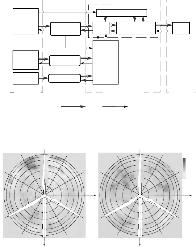
Fig. 8-23 Simulated wind field in the rotor plane of a wind turbine at two consecutive times;
mean wind speed of 12m/s is subtracted
For this purpose, times series of the wind are generated which are based on the
statistical information of the wind under consideration, in general the mean wind
speed, the turbulence intensity, the length scale parameters and the turbulence
spectra (cf. section 4.2.5). These time series, which also incorporate wind compo-
nents perpendicular to the main wind direction, are applied to the swept rotor area
at up to several hundred points, Fig. 8-23. An important challenge in this context
