Gasch R., Twele J. (Eds.) Wind Power Plants: Fundamentals, Design, Construction and Operation
Подождите немного. Документ загружается.

312 9.2 Analysis concepts
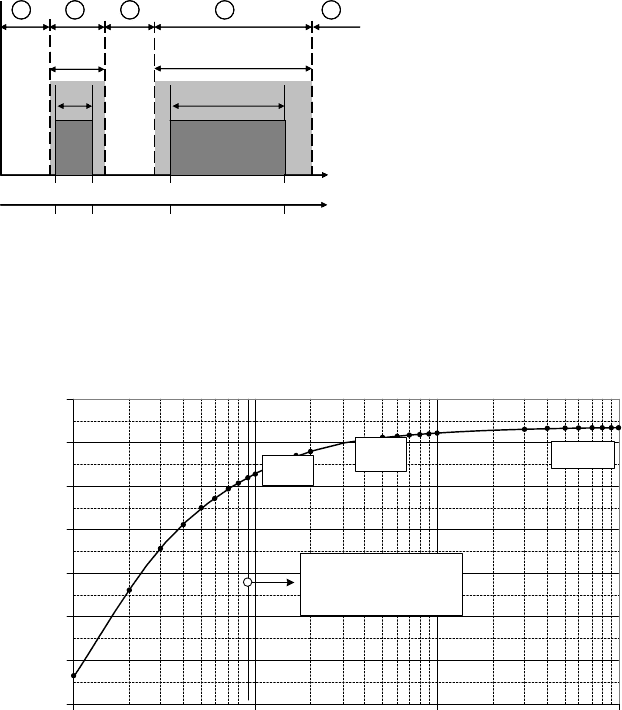
9.2 Analysis concepts
This section treats the basics of the analysis of wind turbine components. In the
following sections 9.3 to 9.5 peculiarities are discussed for the three typical
components: tower, rotor hub and rotor blade.
The analysis of the wind turbine components is based on the assumption that
certain states, so-called ultimate limit states, may not be exceeded. The ultimate
limit states of the component stability comprise:
- Exceedance of the maximum strength (fracture, buckling, fatigue) and
- Loss of equilibrium of the steady-state condition of a structure, e.g. rigid
body tilting.
9.2.1 Ultimate limit state and the concept of partial safety factors
In order to achieve a sufficient reliability the ultimate limit state must be analyzed
for each component in the course of the design. For this purpose, the internal
forces and moments (i.e. bending moment, transverse force and torsion) acting on
the component are considered. The partial safety factors Ȗ
F
for the internal forces
and moments account for the probability of the particular load occurring (e.g.
normal and extreme load, fatigue load), the probable deviation of the load from
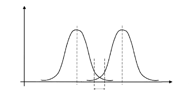
the characteristic values and the accuracy of the load determination, Fig. 9-2. The
characteristic loads F
k
are obtained in general by simulation. The design loads F
d
to be assumed during the analysis are then F
d
= Ȗ
F
F
k
.
The partial safety factors Ȗ
M
for the materials (i.e. material strength of the
component) are used to take into account the dependence of the strength on the
type of material, the processing, the component shape and the influence of the
manufacturing process. The characteristic resistances R
k
divided by the partial
safety factor then gives the design resistances R
d
= R
k
/ Ȗ
M
.
The analysis procedure for the component is then performed in such a way that
for the individual ultimate limit state the stress S corresponding to the relevant
design load F
d
is determined: S = S(F
d
). The resulting stresses (i.e. stress, strain,
bending) then have to remain below the design resistances: S < R
d
.
The values of the partial safety factors Ȗ
F
and Ȗ
M
are given in the standards and
guidelines (GL guideline, IEC 61400-1). Since in the individual documents the
safety factors may differ, the analysis of a wind turbine must be performed with a
system of consistent standards.
To some extent national rules and guidelines may apply other systems than the
presented system of partial safety factors. In Germany, for example, the
foundation is analysed according to DIN1054 using global safety factors, i.e. no
difference is made there between the safety factors for load and material.
9 Guidelines and analysis procedures 313
Safety
range
S, R
Material
resistance R
Stress S from internal
forces and moments F
(actions)
Frequency of occurrence
S R
d
Safety
range
S, R
Material
resistance R
Stress S from internal
forces and moments F
(actions)
Frequency of occurrence
S R
d
Fig. 9-2 Frequency distribution of the stress S in the section and resistances R
9.2.2 Serviceability analysis
A typical criterion for serviceability is the distance between the tip of the rotor
blade and the tower. In operation, the blade tip should never touch the tower
surface. Since the rotor blade bends strongly due to the thrust forces the bending
of the blade and the distance of the rotor blade tips to the tower is analyzed for
every load case (extreme loads and fatigue loads, cf. section 9.5.1). At maximum
bending this distance may not go below 30% of the static rest position of the rotor
blade [1].
With regard to the vibration behaviour of the entire wind turbine it has to be
avoided that under operation the rotational frequency or its harmonics coincide
with natural frequencies of the system, cf. chapter 8. For the rotor blade, the
typical natural frequencies of the sub-system are the first flapwise and the first
edgewise bending natural frequency. Higher order natural frequencies of the rotor
blade are in most cases in uncritical ranges. For the sub-system of nacelle mass,
tower and foundation the first and second bending natural frequency of the tower
are considered. In lattice towers which are, compared to steel tube and concrete
towers, relatively soft in terms of torsion, at least the first torsional natural
frequency must be taken into account. For the analysis, the frequency ratios are
put into the so-called Campbell diagram for all relevant rotational speeds in the
operating range, cf. sections 8.1 to 8.3.
314 9.2 Analysis concepts
9.2.3 Basics of fatigue analysis
A characteristic of wind turbines is the operational stress from vibrations. In the
typical design lifetime of 20 years load cycle numbers in the order of 10
9
are
reached, which is significantly higher than for other technical applications.
Common load cycle numbers are in the order of
5 · 10
6
(airplane), 10
7
(bridge) and 10
8
(helicopter).
Therefore, the fatigue analysis of wind turbines is of prime importance.
The fatigue analysis, or lifetime calculation, serves for designing a component
with a defined lifetime under the assumption of a reasonable failure probability
determined by technical, economic and safety aspects [5].
The concept of fatigue analysis relies on the comparison of a time series of the
stresses with the characteristic curve of the design resistance which is the
S/N curve (Wöhler curve). The latter is determined by constant amplitude tests
until the (technical) initial crack occurs. It is the representation of the stress (or
strain) amplitude S versus the number N of stress cycles performed.
400
350
300
250
200
150
100
50
0
500
Peak-to-peak
amplitude [kNm]
1000
1500
2000
2500
Mean value [kNm]
-1000
-800
-600
-400
-200
0
200
400
600
800
Number of load
cycles [-] *10ˆ (-6)
400
350
300
250
200
150
100
50
0
500
Peak-to-peak
amplitude [kNm]
1000
1500
2000
2500
Mean value [kNm]
-1000
-800
-600
-400
-200
0
200
400
600
800
Number of load
cycles [-] *10ˆ (-6)
400
350
300
250
200
150
100
50
0
500
Peak-to-peak
amplitude [kNm]
1000
1500
2000
2500
Mean value [kNm]
-1000
-800
-600
-400
-200
0
200
400
600
800
Number of load
cycles [-] *10ˆ (-6)
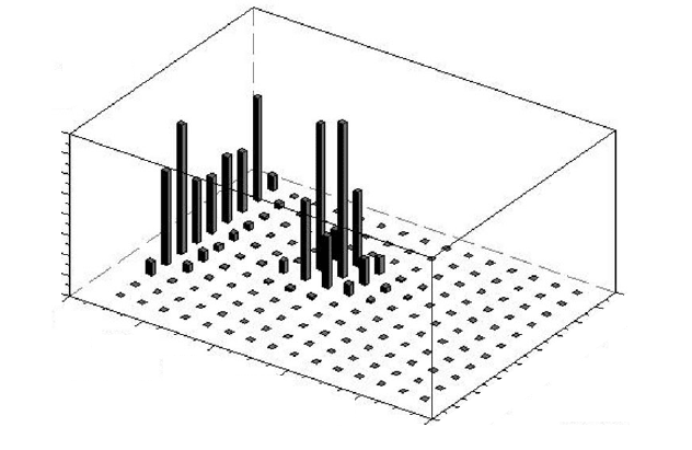
Fig. 9-3 Load cycles versus mean value and amplitude (peak-to-peak) from rainflow count
For the damage accumulation calculation (i.e. the comparison of the stresses with
the S/N curve) the time series of the stresses is either determined by measurement
or simulation. It is divided into the single stress cycles and then compressed into a
spectrum. Different counting methods are common, but the damage content is at
best represented by the rainflow count method. This is a two-parametric method
with which information on the amplitudes and the corresponding mean values is
obtained and displayed as a matrix, Fig. 9-3.
9 Guidelines and analysis procedures 315
For an existing load matrix the relevance for damage accumulation of the load
must be determined depending on the component (i.e. its shape). Component
failure is accelerated, for example, by notches. This behaviour is expressed by the
stress concentration factor and the notch effect number. Depending on the shape
and material, the magnitude of the mean stress leads to an accelerated failure. The
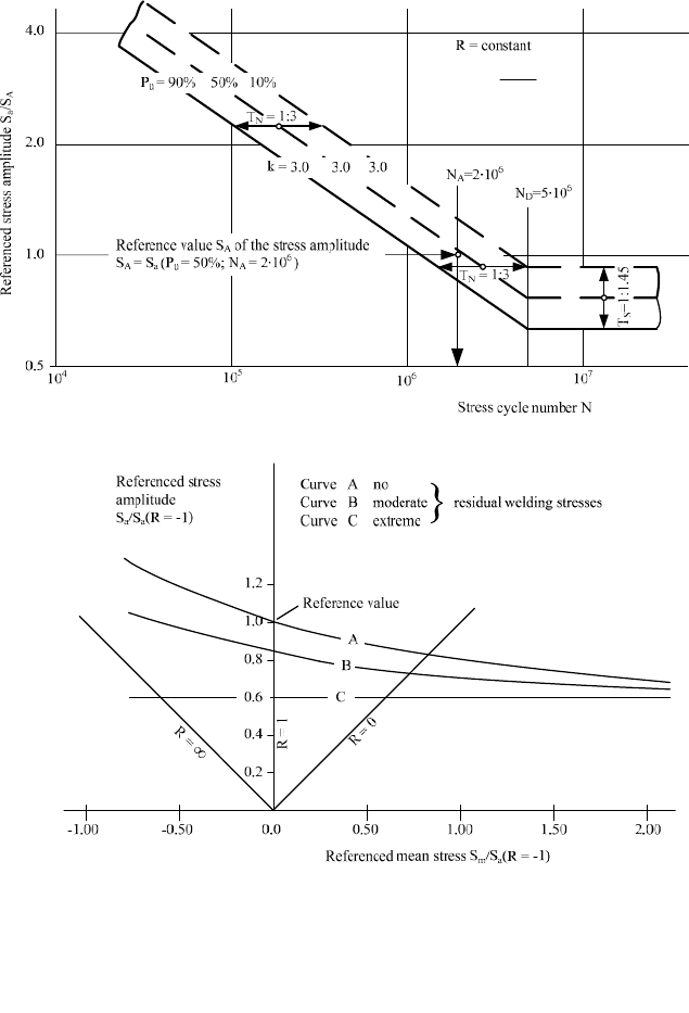
choice of an adapted S/N curve is the key to considering these influences. S/N
curves for different load cases are given and sorted by categories in [6, ECCS
Technical Committee]. The sensitivity to the mean stress is quantified there as
well. The principle is shown in Fig. 9-4. P
Ü
is the failure probability.
In a next step, the contribution of each stress cycle to the cumulative damage
ratio is determined. Typically, the linear damage accumulation hypothesis accord-
ing to Palmgren-Miner is used where the stress is classified according to mean
stress S
mi
and applied stress amplitude S
ai
, which is half of the applied peak-to-
peak stress range'S = 2 S
ai
= S
max
- S
min
. In the class i, N
i
is the number of
endured stress cycles according to S-N curve which is tolerable in the design fatigue
life, and n
i
is the applied number of stress cycles drawn from the fatigue load
spectra. The partial damage ratio
'
D
i
of class i is then
'D
i
= n
i
/ N
i
with n
i
= n (S
ai
, S
mi
) and N
i
= N (S
ai
, S
mi
) , (9.1)
A cumulative damage ratio of D = 1 corresponds to a calculated component
failure exactly at the end of the planned service life, which is in general 20 years.
Therefore, the aim of the design is that in all considered sections the cumulative
damage ratio D is below one:
D < 1 ,
meaning that the calculated design fatigue life exceeds the planned service life.
If the considered material has an fatigue strength limit, as it is the case e.g. for
structural steel in a mildly corrosive environment, and if the amplitudes of all load
cycles are below this fatigue strength limit, then there will be no damage, no
matter how many stress cycles occur.
However, it is more often the case, that some of the stress cycles exceed the
fatigue strength limit or that the material, e.g. aluminum, has no fatigue strength
limit. For this case the fatigue analysis can be performed using the above
equations.
For welding seams it was found that under a loading, the residual stresses, which
where n
i
: Number of applied stress cycles of class i occurring during
design fatigue life, drawn from fatigue load spectra
N
i
: Number of endured stress cycle of class i according to S-N curve,
S
ai
: Applied stress amplitude
S
mi
: Mean stress
The cumulative damage ratio is the linear sum of the partial damages:
D =
Σ
Δ
D
i
. (9.2)
316 9.2 Analysis concepts
are nearly inevitable, have an influence equivalent to the mean stress. Accord-
ingly, the influence of the actual mean stresses is lowered, so the permissible
stress cycle number depends in the end only on the stress amplitude. This allows a
simplified analysis at which the rainflow matrix is reduced to an equivalent
constant-range stress spectrum and the influence of the mean stress is included in
the S/N curves. This procedure and the corresponding S/N curves are found, for
example, in Eurocode 3.
ae
1R
SR
2
§·
¨¸
©¹
Fig. 9-4 Normalised S/N curves (Wöhler curve) for welded structures and dependency on the
mean stress [7]
9 Guidelines and analysis procedures 317
9.3 Example: Tubular steel tower analysis - mono-axial stress
state and isotropic material
9.3.1 Ultimate limit state analysis, analysis of extreme loads
Determination of the stress in the wall of the tower
A substantial analysis of the tubular steel tower treats the determination of the
stresses occurring in the wall of the tower. Here, mostly global approaches are
applied in which the results of the simulation model including the additional loads
from 2
nd
order theory (deformed system) are investigated for several sections. The
stresses are then determined section by section using the simple approach:
Bending stress equals local moment in the section divided by the local section
modulus.
The stresses so obtained are then compared to the admissible values according
to DIN 18800 or Eurocode 3 and must be smaller than these.
For edge-stiffened openings, required, at the doors, for example, local FEM
analysis is performed for investigating the stress concentration produced by the
stiffness changes. These stress concentrations must also be applied in later fatigue
analyses. Alternatively, for the stress analysis the complete structure can be mod-
elled using FEM, but this requires a greatly increased computing time.
Analysis of buckling
The tower has a relatively small wall thickness (t = 10…50 mm) in relation to its
diameter (in the range of meters). Therefore, one possible case of failure is the
buckling of the tower shell. In this non-linear failure case there is plastic
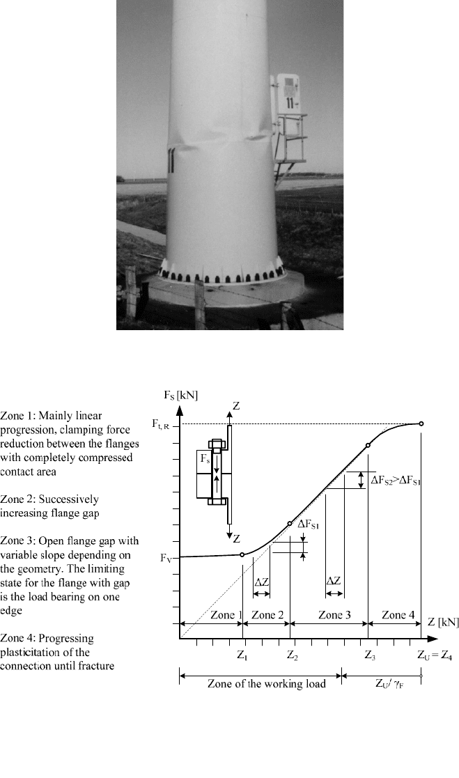
deformation of the tower shell which leads to a new state of equilibrium, Fig. 9-
5. The corresponding analysis is given by DIN 18800-4. For wind turbines towers
a
correction for buckling under bending stress must be taken into account since this
is the main stress type [8]. At local spots and sections, for example openings,
further analysis is required.
318 9.3 Example: Tubular steel tower analysis - mono-axial stress state and isotropic material
Fig. 9-5 Buckling of a tower
Fig. 9-6 Loading zones of an ideal bolted flange connection depending on the load according to
[10]. Preload F
v
of the bolt, force Z in the tower segment and additional bolt load F
S
9 Guidelines and analysis procedures 319
Analysis of the flange connections
Due to production and transportation requirements the towers of wind turbines are
manufactured in several sections and bolted together by their ring flange connec-
tions during erection on site. For this type of connection there are several analysis
procedures [9]. In the following, only the basic relationships are presented.
Depending on the geometry of flange and the bolt as well as the pre-stressing
conditions, there is a certain ratio of the force Z in the tower’s wall segment and in
the bolt F
S
. The diagram in Fig. 9-6 shows the different zones for an ideal bolted
flange connection.
In order to use the preloading of the flange-bolt system according to Fig. 9-6, the
specifications have to be respected. In particular, one must ensure that the flanges
are even and parallel since a gap in the flange connection leads to a strong
increase in loading on the bolts.
9.3.2 Fatigue strength analysis
The fatigue strength analysis of steel towers follows in general the nominal stress
approach. The loadings are provided by the simulation programs through the
internal forces and moments at the position of the analyzed component and
transferred to the local stress level. Then, the damage sum is calculated using the
load spectra and applicable class of geometric discontinuity from DIN 4131 or
Eurocode 3.
For more complex components, e.g. the flanges and openings, FEM models are
necessary to determine the stress level. One must bear in mind that the stress
concentrations calculated by FEM analysis may not be combined with the reduced
design S/N curves for the corresponding component since these curves already
take into account the stress concentration.
9.3.3 Serviceability analysis, natural frequencies analysis
In order to determine the natural frequencies of the tower, FEM models created for
the global stress calculations are for the most part applied. Alternatively, there are
approximation formulae, e.g. according to Morleigh in [9].
The natural frequency of the tower should have a distance of more than 10% to
the exciting frequencies of the wind turbine, 1ȍ and 3ȍ. For a large wind turbine
the admissible and inadmissible frequency ranges are shown in Fig. 9-7.
When calculating the natural frequencies, correct and reasonable clamping
conditions have to be considered. If the soil is too soft (e.g. around the monopiles
for offshore wind turbines) this may unduly lower the natural frequencies of the
320 9.3 Example: Tubular steel tower analysis - mono-axial stress state and isotropic material
overall system. It is usual to define a required minimum spring stiffness for the
tower design, which then has to be verified in the planning procedure by a geo-
logical survey. Fig. 9-8 shows the relations between soil spring and natural
frequency.
0.153 0.255 0.460 0.765
45.927.69.2 15.3 Rotor speed in rpm
Excitation frequency f in Hz
1 Extreme soft tower design, mostly not
possible due to material strength
2 Soft design (soft-soft), requires
controlled resonance passage
3 Soft-stiff, classical design, natural frequency
of the tower between 1p and 3p range
4 Problematic design, not recommended
5 Very stiff design, hardly economic
3p1p
1p±10% 3p±10%
1 2 3 4 5
Fig. 9-7 Frequency ranges for the tower design [10]
Range of expected
clamping stiffnesses
of the soil spring
0.327
0.322
0.307
Soil spring stiffness [kNm/rad]
0.34
0.32
0.3
0.28
0.26
0.24
0.22
0.2
1.00E+07
1.00E+08
1.00E+09
1.00E+10
f
O
in Hz
Fig. 9-8 Natural frequency f
O
of the tower depending on the soil spring stiffness [9]

9 Guidelines and analysis procedures 321
9.4 Example: Rotor hub analysis - multi-axial stress state and
isotropic material
Rotor hubs of modern wind turbines are usually components cast from EN-GJS-
400-18-LT (formerly known as GGG-40.3), cf. chapter 3. This material allows the
production of complex geometries with good material strength and relatively low
weight.
9.4.1 Geometric design
The hub links the blades to the rotor shaft flange; therefore its shape and size is
determined by these components, especially by the diameter of the blade flange
connection and the blade.
If the connection dimensions are known, the actual shape of the hub has to be
determined. Due to the complex geometry FEM programs are required for this
purpose. Several years ago, it was common to choose a sphere or star shape, Fig.
9-9, where the latter offers the possibility of increasing the rotor diameter using
extenders at the cylindrical parts of the hub. Nowadays, the rotor hub is
topologically optimised: an optimisation algorithm in the FEM program varies the
wall thickness according to the local stress and searches for a solution with
minimal use of material. These hubs then have the shape of an apple with
additional openings in zones where no material is needed.
Sphere hub Star hub Topologically optimized
hub
Sphere hub Star hub Topologically optimized
hub
Fig. 9-9 Typical shapes of rotor hubs
