Gasch R., Twele J. (Eds.) Wind Power Plants: Fundamentals, Design, Construction and Operation
Подождите немного. Документ загружается.

8.3 Simulation of the overall system dynamics
302
of time series generation is to reach not only a temporal but also a spatial correla-
tion of the wind in the swept rotor area which is comparable to the “real” wind.
The effect of partial gusts (cf. section 8.1) is represented only realistically by
means of this high modelling effort.
Moreover, the wind fields are simulated by deterministic description of the in-
flow. This procedure is used especially for the calculation of wind turbines ma-
noeuvres. One example is the design load case DLC 1.3 according to IEC 61400
where during power production an extreme coherent gust with a simultaneous
strong change of the wind direction has to be modelled.
Modelling of the aerodynamics
The next step in the simulation is the representation of the flow conditions at the
rotor blade as well as the forces and moments. For this purpose mainly the model
of the blade element momentum theory is applied as it was presented in chapters 5
and 6. For every time step a complete iteration for the determination of the bal-
ance of forces and flow conditions is calculated. Thereby, the aerodynamic influ-
ences of 3D effects (stall delay, etc.) are transferred as well as possible from a 3D
to a 2D calculation. Basically, the equations of chapter 6 are applied to each indi-
vidual blade section. But the inflow is combined from mean wind speed at the sec-
tion and the turbulence. Deterministic effects like oblique flow and vertical profile
are considered as well.
The huge amount of computation time required inhibits the application of “modern”
3D numerical flow simulation methods which are today commonly applied in air-
craft and turbine design. It would be necessary for these simulations to represent
the unsteady character of the wind field, as described in the previous section, at
each point of the rotor blades. Even if computer performance increases in the same
order as in recent years, acceptable computing times for the CFD application will
not be reached in the near future.
Modelling of the structural dynamics
This part of the simulation is essential for the overall results but is by no means
specific to wind turbines. There are as many methods as there are approaches to
structural modelling. The particular challenge of the strong deformations and the
consecutive non-linearities are no longer a problem for the commonly applied
methods. For this issue, in particular, the modelling depth and the applied method
strongly influence the simulation speed and therefore the application purpose. At
present, approaches based on multi-body simulation are mainly used, which are
then linked to the modal analysis for components which may be reduced to an
elastic beam model. To speed up the modelling process it is rare to include more
than the first two modal degrees of freedom. To increase the depth of modelling
8 Structural dynamics
303
for a more detailed investigation of components an FEM approach is later used
which means increasing the computation time. The aeroelastics additionally take
into account the change of velocity triangles and the orientation of the blade
section by deformations and movements, not only of the blade but of the entire
structure.
8.3.2 Application of simulation programs
As already mentioned in the introductory section of this chapter, the main areas of
the application of simulation programs are the load and certification calculations,
the initial design and power curve computations as well as wind turbine optimisa-
tion. These fields of application are discussed more closely in the following.
The entire determination of the loads and the calculation for certification has to
be divided into two completely different branches: fatigue analysis (for operating
loads) and ultimate limit state calculation (for extreme loads), which are discussed
in chapter 9 in detail.
The basic procedures in the simulation runs and the applied models are identi-
cal, but the simulation control and evaluation significantly differ. The calculation
of the loads for fatigue analysis is performed through the simulation of different
mean wind speed classes for (commonly) 10-min time series. The amplitudes and
the load distribution are directly determined by counting the simulated loads, fol-
lowed by a temporal weighting using a Weibull distribution: the results of each
class are extrapolated according to their class frequency to a lifetime of 20 years.
For the ultimate limit state verification the manoeuvres of a wind turbine are simu-
lated as closely as possible for different environmental conditions, e.g. the above
mentioned design load case 1.3 according to IEC, see also section 9.1.7.
Another field of application is the direct coupling of the controller software of a
wind turbine with the simulation (“hardware in the loop”). For this purpose, the
modelling of the wind is directly coupled to a “real” hardware controller, which is
given the illusion of a real environment by the sensor impulses. The reactions are
then fed back into the simulation model of the turbine. The aims are, on the one
hand, the verification of the controller and, on the other, gaining knowledge on the
loading of the turbine structure during real controller actions. Nowadays, exactly
the same software is more and more incorporated in both the real and simulated
controllers to facilitate the exchange between real and simulated control. The
software only has to be translated for the different platforms.
8.4 Validation by measurement
304
8.4 Validation by measurement
The application of programs for wind turbine design and simulation is only
reasonable if the computed results are confirmed by measurement results from real
wind turbines. Different perspectives are relevant from the point of view of the
design engineer:
- Verification of important model parameters, e.g. natural frequencies,
damping, time constants
- Influence of the wind turbine behaviour and the controller on the power
curve and the energy yield
- Validation of the fatigue loads
- Traceability of the loads during operation and manoeuvres
- Additionally: validation of the applied modelling of the wind
The most striking problems are always the reliable measurement of the wind
speeds and their direct comparison with the synthetic wind speed in the entire
swept rotor area. This would require virtually the exact measurement of the wind
speed in the entire swept rotor area – e.g. at all points shown in Fig. 8-23. This is
practically impossible for physical and metrological reasons.
Therefore, already the reliable determination of the power curve is a problem
which is aggravated by problems of calibration. Thus, useful results are obtained
only by the statistics of long-term measuring campaigns. The 10-min mean values
are recorded and sorted using the method of bins. In addition to classification of
the wind speeds into bins further classification is performed according to the tur-
bulence intensity.
Fig. 8-24 shows a typical matrix (“capture matrix”) for classifying the measured
10-min values. Each bin (i.e. matrix cell) is defined by the pair of wind speed
class of the column and turbulence intensity class of the row and notes how many
corresponding 10-min values were measured. According to this classification, the
simulation of the 10-min time series is performed. The simulation results are
sorted accordingly in order to achieve an easy statistical comparison with the
measured forces and moments. They need only to be weighted with an arbitrary
temporal distribution (e.g. by the Weibull distribution as required in the IEC
61400 standard) and may then be noted directly as vibration amplitude distribution
(and then compared with the calculated result).
The following points are considered for the evaluation:
- bending moments at the blade root (or moments in the entire blade),
- forces and moments at the bearings,
- moments in the drive train as well as
- bending moment at the tower base.
Then, from this data set, a variety of loadings of the specific wind turbine compo-
nents may be determined or derived.

8 Structural dynamics
305
Time series length
Wind speed in m/ s
4 5 6 7 8 9 10 11 12 13 14 15 16 17 18 19 20 21 23
Turbulence
intensity I in %
<3 0100000000000000000
3-5 21020000000000000000
5-7 52396100000000000000
7-9 83028231653131000010000
9-11 13 45 62 51 45 45 21 15 10 7 8 1 6 2 6 4 0 0 0
11-13 14 74 121 170 125 88 75 52 48 43 18 18 29 29 25 10 2 2 0
13-15 15 89 116 191 200 146 103 77 86 64 46 49 51 50 23 6 2 0 0
15-17 17 70 101 160 147 108 109 65 51 61 49 57 39 18 11 6 2 0 0
17-19 9295357484936292230343132 8 4 0 0 0 0
19-21 5162113151610 9 2 8 9 6 4 2 0 0 0 0 0
21-23 41110636104100000000
23-25 0143100001000000000
25-27 1301100100000000000
27-29 1010000000000000000
>29 1110000000000000000
Number of turbu-
lence classes with
more than 3 series
910910888667656454000
Total number 95 393 520 695 613 468 363 256 228 226 171 167 167 113 75 30 6 2 0
Capture matrix: normal operation, Wind speeds: mean values of the class
Operation at rated power
Wind speed class per 1 m/s
Turbulence class per 2%
Number of 10-min records per bin
Fig. 8-24 “Capture matrix”: Classification of measured 10-min time steps by mean wind speed
and turbulence intensity
References
[1] T. Burton, et al. : Wind Energy Handbook, Wiley, 2002
[2] IEC 61400-1 ed.3
[3] Kühn, M.: Dynamics and Design Optimisation of Offshore Wind Energy Conversion
Systems, Dissertation, TU Delft, 2001
[4] Gasch, R., Twele, J.: Windkraftanlagen (Wind Power Plants), 3rd edition, p.188,
Teubner, Stuttgart, 1996
[5] Maurer, J.: Windturbinen mit Schlaggelenkrotoren – Baugrenzen und dynamisches
Verhalten (Wind turbines with flapping hinge rotors - constructional limits and
dynamic behaviour), VDI-Verlag, series 11, No. 173, Düsseldorf, Germany 1992
[6] Magnus, K.; Popp, K.: Schwingungen (Vibrations), 5th edition, Teubner, Stuttgart,
1997
[7] Gasch, R.; Knothe, K.: Strukturdynamik (Structural dynamics), Vol. 1, Springer,
Berlin, 1987
[8] Measurement by Deutsche WindGuard Dynamics GmbH, Berlin
[9] Data from EUROS Entwicklungsgesellschaft für Windkraftanlagen GmbH, Berlin
[10] Institut für Maschinenelemente und Maschinenkonstruktion (Institute of Machine
Elements and Machine Design), Technical University Dresden, 30
th
July 2005,
http://www.me.tu-dresden.de/forschung/dynamik.shtml.de
[11] Gasch, R.; Nordmann, R.; Pfützner, H.: Rotordynamik (Rotordynamics), 2
nd
edition,
p. 637, Springer, Berlin, 2002
[12] Det Norske Veritas (DnV): Guidelines for Design of Wind Turbines, 2
nd
ed., 2002
[13] Kaiser, K.: Luftkraftverursachte Steifigkeits- und Dämpfungsmatrizen von Windtur-
binen und ihr Einfluß auf das Stabilitätsverhalten (Stiffness and damping matrices of
8.4 Validation by measurement
306
wind turbines caused by aerodynamic forces, and their influence on stability), VDI-
Verlag, Series 11, No. 294, Düsseldorf, 2000
[14] Hansen, M.H.: Improved modal dynamics of wind turbines to avoid stall-induced
vibrations, Wind Energy, 6, 179-195, 2003
[15] Quarton, D.C.: The Evolution of Wind Turbine Design Analysis – A Twenty Years
Progress Report, Wind Energy, 1, 5-24, 1998
R. Gasch and J. Twele (eds.), Wind Power Plants: Fundamentals, Design, Construction 307
and Operation, DOI 10.1007/978-3-642-22938-1_9, © Springer-Verlag Berlin Heidelberg 2012
9 Guidelines and analysis procedures
9.1 Certification
In general, certification is understood as the verification of entire companies,
operating procedures or products for their compliance with certain criteria. Today,
the certification of products and manufacturers is a standard in the sector of wind
energy. The certification (of conformity) is a measure carried out by independent
institutions (or persons) which document that a certain product, procedure or
service is in accordance with a certain standard or some other specific normative
document (EN 45011, EN 45012, EN 45013).
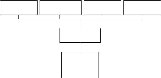
Fig. 9-1 gives an overview of the fundamental elements of the wind turbine
type certificate.
Design
assessment
Implementation
in manufacturing
QM System
Final
assessment
Type
certificate
Prototype test
Design
assessment
Implementation
in manufacturing
QM System
Final
assessment
Type
certificate
Prototype test
Fig. 9-1 Elements of the wind turbine type certificate [1], modified
Certification is based on the above mentioned standards or normative documents.
In this context, distinction should be made between specific standards for the wind
energy sector and general standards. At first an overview of the specific standards
for the wind energy sector is given, subsequent sections will make reference to
general standards.
Apart from the certification of product and manufacturer there is partly an
additional project specific assessment, especially if the site conditions are not
covered by the general certification scheme.
The so-called due diligence is also a site-specific assessment which focuses on
the assessment of the recoverability of a project. This comprises design aspects,
e.g. if the site conditions are covered by the general certification and if all design
assumptions are applicable. Since in general the client of such a due diligence is
the future project operator or the investor, this assessment is extended to questions

308 9.1 Certification
on the accuracy of the yield prognosis as well as the prospective guarantee and
service concepts.
9.1.1 Standard for certification: IEC 61400
The International Electrotechnical Commission (IEC) has bundled together under
the number 61400 several standards relating to different sectors of the wind
energy. The work at these standards is a continuous process which led to several
revisions of some of these standards in the past years. The reader should make
sure that he is always informed on the current revisions of the standards.
All these standards have been developed especially for the wind energy sector.
The IEC 61400-1 is of very high importance because it describes the basic -
relationships between site data and load assumptions for the simulation of a wind
turbine and is therefore the starting point for any design procedure.
It has to be noted that due to their date of issue the guidelines mentioned in the
following may partly refer to older editions of some of the IEC 61400 standards.
Several parts of IEC 61400 are issued as European standards, e.g. EN 61400-1.
Table 9.1 Overview of the standards IEC 61400 according to [13]
IEC 61400–1 Design Requirements
IEC 61400–2 Design Requirements of Small Wind Turbines
IEC 61400–3 Design Requirements for Offshore Wind Turbines
IEC 61400–11 Acoustic Noise Measurement Techniques
IEC 61400-12-1 Power Performance Measurements of Electricity
Producing Wind Turbines
IEC 61400-13 Measurement of Mechanical Loads
IEC 61400-14 Declaration of apparent sound power level and tonality
values
IEC 61400-21 Measurement and Assessment of Power Quality Cha-
racteristics of Grid Connected Wind Turbines
IEC 61400-22 Conformity testing and certification
IEC 61400-23 Full-Scale Structural Testing of Rotor Blades
IEC 61400-24 Lightning Protection
IEC 61400–25 Communications for Monitoring and Control
of Wind Power Plants
9 Guidelines and analysis procedures 309
9.1.2 Guidelines for the Certification of Wind Turbines by
Germanischer Lloyd
This document [1] is not a standard but a guideline, a recommendation for a
certain procedure. The fundamental elements are based on the IEC 61400
standards, but the main focus is the description of the design and analysis
procedures for the components of a wind turbine. In this context, the major focus
is the product safety. The latest edition in 2010 mentions the national requirements
in Germany, Denmark, Netherlands, Canada, India, China and Japan.
9.1.3 Guidelines for Design of Wind Turbines by DNV
Similar to the GL guideline this document [2] by Det Norske Veritas, DNV,
describes several aspects of the design procedure of wind turbines. The fundamental
points and relationships are treated which are essential to attain certification.
Again, the basis for this procedure is the IEC 61400 and further relevant
standards.
9.1.4 Regulation for Wind Energy Conversion Systems, Actions
and Verification of Structural Integrity for Tower and Foundation
by DIBt
In Germany, the tower and foundation of a wind turbine are considered as a
building structure and are subject to the relevant permission procedure [3]. The
Deutsche Institut für Bautechnik (DIBt, German Institute for Civil Engineering)
issued a specific regulation which describes the required analyses for a wind
turbine. Although this regulation is not a standard it has a normative character.
Deviations from the given approaches are not allowed. This regulation was reissued
in 2004 in a second, heavily revised edition with load case definitions based on the
2
nd
edition of IEC 61400-1. In other parts of the regulation, concepts from civil
engineering are applied.
9.1.5 Further standards and guidelines
Apart from the standards and guidelines mentioned above there are some country-
specific versions or differing approaches. In the Dutch NVN guideline the IEC
standards are adopted, but in some parts there are modifications, e.g. concerning

310 9.1 Certification
the required safety factors. The Danish standards DS472 (Loads and Safety of
Wind Turbine Constructions) and a series of guidelines govern the requirements
for wind turbines in Denmark (e.g. http://www.wt-certification.dk/UK/Rules.htm).
9.1.6 Wind classes and site categories
One basic concept of the IEC standards, and the guidelines which refer to it, is the
classification of the environmental conditions in wind classes. In the IEC 61400-1,
2
nd
edition, there are four different wind classes defined. In each class there are
fixed relationships between the fundamental design parameters: annual average
(i.e. mean) wind speed V
ave
, characteristic turbulence intensity T
I
and extreme
wind speed V
e
, shown in table 9.2. The 3
rd
edition of IEC 61400-1 was issued in
2005, but many national standards and guidelines are still based on the 2
nd
edition.
Table 9.2 Design wind speeds V and characteristic turbulence intensities T
I
of the type classes
according to IEC 61400-1, 2
nd
. ed.
Wind class I II III IV
Extreme load Unit Comment
V
ref
= V
m50
50.0 42.5 37.5 30.0 m/s Expected extreme 50-years
wind, 10-min average
V
e50
70.0 59.5 52.5 42.0 m/s
3-sec average
V
m1
37.5 31.9 28.1 22.5 m/s
wind, 10-min average
V
e1
52.5 44.6 39.4 31.5 m/s
wind, 3-sec average
Fatigue strength
V
ave
10.0 8.50 7.50 6.00 m/s
speed at hub height
T
IA
18.0 18.0 18.0 18.0 %
intensity at V = 15 m/s,
Class A
T
IB
16.0 16.0 16.0 16.0 %
intensity at V = 15 m/s,
Class B
If one follows this concept for the wind turbine design, a wind class must be se-
lected at the beginning of the design procedure which corresponds as much as
possible to the conditions in the target market and therefore allows a design which
is not only economically efficient but also meets the expected loads. A series of
Extreme 50-year wind,
Expected annual extreme
Expected annual extreme
Annual average wind
Characteristic turbulence
Characteristic turbulence
9 Guidelines and analysis procedures 311
load case definitions is derived from the chosen wind class, which form the basis
for analysing the wind turbine.
Later, in the realisation planning of a certain wind farm project (cf. chapter 15)
a site-specific assessment of the chosen wind turbine must be made for checking
whether the design wind class covers the real on-site wind conditions including
the wind farm effects. Otherwise, new load calculations must be performed in
order to show that the wind turbine design includes enough reserves and is
therefore still suitable. For sites which do not correspond to the given relationships
it is possible to define a “special class” in which the site-specific relationships
may defined arbitrarily.
9.1.7 Load case definitions
In the concept of the IEC 61400 two different categories of load cases are
analyzed: on the one hand, the extreme load cases where the stability of the wind
turbine has to be assured (ultimate limit state), and on the other hand, the load
cases under operation which are used for the fatigue strength analysis.
Extreme load cases are mainly defined by the occurring gust wind speeds.
Typical design load cases (DLC) which cause high stress are the 50-year extreme
wind speed (DLC 6.1) and the extreme operating gust combined with an extreme
change of the wind direction (DLC 1.3). However, there are also operating condi-
tions which result from the failure of the control systems and cause critical load
cases, e.g. the failure of a pitch drive followed by an emergency stop at overspeed,
cf. section 8.1.3. In order to describe the spatial structure of the gusts, deterministic
gust shapes are assumed for some of the load cases, but stochastic time series with
high turbulence intensity are applied as well.
The fatigue strength load cases are basically calculated from stochastic time
series of the three-dimensional wind field. For several mean wind speeds between
cut-in wind speed and cut-out wind speed, 10-min time series of the wind are
generated and then applied in the simulation program to obtain the stresses. These
are then weighted according to the mean wind speed of the selected wind class and
extrapolated to the operating lifetime of 20 years, cf. section 8.3. Additionally, the
start-up and shut-down cycles are simulated in order to take into account the
corresponding loadings as well.
Safety factors are applied to all load cases. For the individual load cases and
load components different magnitudes of the factor are defined according to the
accuracy of the predictability and the probability of occurrence, as well as the
consequences for the wind turbine safety.